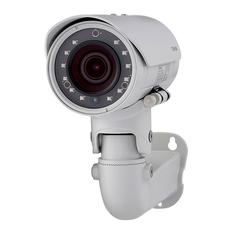
VISUALINT VI-4300 User manual

VI-4300
Installation Guide

INFORMATIONTOUSER
CAUTION
RISKOFELECTRICSHOCK,
DONOTOPEN
CAUTION:TOREDUCETHERISKOFELECTRICSHOCK,
DONOTREMOVECOVER(ORBACK).
CONTACTQUALIFIEDSERVICEPERSONNELFORINTERNALPARTS.
This symbol is intended to alert the user the presence of uninsulated
“dangerousvoltage”withintheproduct’senclosure,whichmaybesufficient
magnitudetoconstituteaelectricshockrisktopersons.
Thissymbolisintendedtoalerttheuserthepresenceofimportantoperating
andmaintenance(servicing)instructionswithintheguidemanual.
!
!

VI4300InstallationGuide
01A.08 3
Table of Contents
1.FEATURES..............................................................................................................4
2.PACKAGECONTENTS..............................................................................................5
3.PARTNAMES.........................................................................................................6
4.INSTALLATION.......................................................................................................7
4.1.InstallationTemplate.........................................................................................................8
4.3.SettingtheImageAttribute...............................................................................................9
5.CONNECTIONS.....................................................................................................10
6.CONFIGURATION.................................................................................................13
6.1.Setupnetworkenvironment...........................................................................................13
6.1.1.GenericIPEnvironment............................................................................................13
6.1.2.CustomIPEnvironment............................................................................................14
6.2.Viewvideoonwebpage..................................................................................................15
6.2.1.AccessthroughIPAdminTool...................................................................................16
6.3.Reset................................................................................................................................17
6.4.FactoryDefault.................................................................................................................17
APPENDIX(A):SPECIFICATIONS...............................................................................18
Summary.................................................................................................................................18
ElectricalCharacteristics.........................................................................................................19
EnvironmentCondition...........................................................................................................19
MechanicalCondition.............................................................................................................19
APPENDIX(B):POWEROVERETHERNET..................................................................20
PoEcompatibility....................................................................................................................20
Powerclassification................................................................................................................20
APPENDIX(C):DIMENSIONS....................................................................................21
APPENDIX(D):HEXADECIMALDECIMALCONVERSIONTABLE..................................22
REVISIONHISTORY..................................................................................................23

VI4300InstallationGuide
01A.08 4
1
1
.
.
F
F
E
E
A
A
T
T
U
U
R
R
E
E
S
S
Camera
•FullHDoutdoordomeIPcamera(Vandalproof)
•Highqualitycompressioninrealtimestreaming
•1/2.7”HighQualityCMOSImageSensor
•TrueDay/Night(ICR)andWDR
•Improvementofcolorrollingsuppression
•RemoteZoom/FocusControl(OneClickAF)
•36IRLEDs
Streaming
•Dualstreamingmode(suchasdifferentcodec/resolution/bitrateandsoon.)
•DeinterlacingonDSP
•Burntintextsupported
•Unicast/Multicastsupported
Video/Audio
•Video compression:H.264/MPEG4 (Planned for the future release.)/MJPEG,
25/30FPS@1080p(PAL/NTSC)
•Audiocompression:G.711(µLaw,aLaw)/PCM
•Analogvideooutforexternalmonitors
•Videomotiondetectionsupported
•Twowaymonoaudiosupported
Network
•RTSP/HTTPprotocolsupported
•10/100BaseTEthernet
AdditionalFeatures
•MicroSDcardsupport
•PoEsupport
•BuiltinVideoContentAnalysis
•Internalfanandheater
•IP66certified

VI4300InstallationGuide
01A.08 5
2
2
.
.
P
P
A
A
C
C
K
K
A
A
G
G
E
E
C
C
O
O
N
N
T
T
E
E
N
N
T
T
S
S
Unpackcarefullyandhandletheequipmentwithcare.Thepackagingcontains:
Camera
DCpoweradaptor
DCJackCable
9pinand2pinterminalblock
Videooutcable
Screwsandanchors
Installationtemplate
Hexwrenchdriver
Quickinstallationguide
Siliconwaterproofband
Clampingcore
Topreventelectromagneticinterference
Theabovecontentsaresubjecttochangewithoutpriornotice.
Note
i

VI4300InstallationGuide
01A.08 6
3
3
.
.
P
P
A
A
R
R
T
T
N
N
A
A
M
M
E
E
S
S
①Fan
Thefanandheater(underneaththeblackpanel)areimplementedforcontrollingtemperatureandmois
tureoftheinternaldevice.
②Resetbutton
TheresetbuttoncanbeusedforrestartingthedeviceorresettingittoFactoryDefault.Referto6.3.Re
setand6.4.FactoryDefaultformoredetails.ResetbuttonislocatedunderPCB.
③Outputconfigurationswitch
Referto4.2.SettingtheLensPositionsformoreinformationontheswitch
④Videooutput,audioandIOterminalconnector
A9pinterminalblockisincludedinthedevicepackage.Connectthisterminalblockintothisconnectorf
orcableconnectionofvideooutput,audioinput/outputanddigitalinput/output.Videooutisusedonly
forinstallationandworksfor3minuteswhenPAL/NTSCbuttonispushed.
⑤LANconnector
RJ45LANconnectorfor10/100BaseTEthernet.
⑥MicroSDcardslot
Memorycardslotforexternalstorage.
⑦PowerAdaptorConnector(DC12V)
DC12V3.5Aadapterforpowersupply.
*Modelshereinandtheirappearancearesubjecttochangewithoutanypriornotice.

VI4300InstallationGuide
01A.08 7
4
4
.
.
I
I
N
N
S
S
T
T
A
A
L
L
L
L
A
A
T
T
I
I
O
O
N
N
Topreventproductsfromdamaging,placethecameraonstableandnonvibratin
gsurfaces.Ifthestabilityisindoubt,consultwithsafetypersonnelforreinforcem
ents,andthenproceedwiththeinstallation.
Caution
!
1)Place the installation template(paper)
that is included in the package on the
desiredinstallationsurface.
2)Drill three holes in correct positions
based on the template paper, and insert
anchorblocksintotheholes.
3)Placethewaterproofsiliconbandonthe
bottom plate of the device and make it
alignwithscrewholes.
4)Place the camera body to the
installation surface and match three
alignment holes with three anchor blocks.
Thentightenthesurfaceanchorstuds.
5)Connect all the required cables to the
camera.
6) Adjust the lens position. Detailed
information can be found in 4.2. Setting
theLensPosition.
7)
Placethedomecoveronthemainbody
ofthecamera.Domecoverhasthree
alignmentholesthatmatchcamerabody’s
alignmentholes.
8)Onceproperlyplaced,insertscrewsinto
thethreeholesofthebodyandtighten
themup.

VI4300InstallationGuide
01A.08 8
4.1. Installation Template
Installationtemplateimage’ssizescaleinthisinstallationguideisnot1:1.
Thecorrectsizetemplatedesignpapercanbefoundinsidethepackagesepar
ately.
Caution
!
p

VI4300InstallationGuide
01A.08 9
4
4
.
.
2
2
.
.
Setting the Lens Position
Instructionbelowdescribeshowtosetthelenspositionsandmanuallyadjustzoomandfocus.
1)Removethedomecover.
2)Setthe lens position byrotating the camera gimbal;topan, rotate the reinforced lower
bodyofthegimbal;totilt,verticallyadjustthecameragimbal.
Refrainfromcontinuouslyrotatingthecameragimbalwithexcessiveforce to a
singledirectionasitisattachedwiththeIRLEDcableinsidethedome.
3)Thefigureandtablebelowexplainsthelensswitchsettings.
4.3. Setting the Image Attribute
Throughthecamera’swebpage,userscanconfigureimagesettings.
Thecameraimage’sbrightness,contrast,saturationandsharpnessareadjustablethroughthe
imagesettings.(Setup>Video&Audio>Camera).
Caution
!
C.Tiltthelensbyvertically
adjustingthecameragimbal
B.Topan,rotatethelower
bodyofthecameragimbal
A.Toadjustlensposition,
rotatethecameragimbal
SW1
SW2
SW3
PAL/NTSC
TELE
WIDE
SW4
SW5
SW6
FARNEAR
Auto
Focus

VI4300InstallationGuide
01A.08 10
5
5
.
.
C
C
O
O
N
N
N
N
E
E
C
C
T
T
I
I
O
O
N
N
S
S
①Audioinput/output
Thecamerahasamonoaudioinputandamonoaudiooutput.Duetolowaudiooutputpower,
anamplifiedspeakerisrecommendedforenhancedsound(Donotconnectaheadphoneor
earphonedirectlytothecamera)
②Sensor(DI)connection
Thecameraprovides1channelD/I.Itcanbeconnectedto eitheravoltagetypesensorora
relaytypesensorasthefollowingfigures.Settingscanbedonethroughthecamera’swebpage.
Inputvoltagerange:0VDCminimumto5VDCmaximum,Max50mA
Inputvoltagethreshold:1.5V
Donotexceedthemaximuminputvoltageorrelayrate.
Caution
!
Mic
AmpSpeaker
Out
In
AUDIO
DO DI
1OutOut 1
VIDEO
C C In
AUDIO

VI4300InstallationGuide
01A.08 11
③Alarm(DO)connection
Onlytherelaytypeissupported.
RelayRating:Max24VDC50mA
Donotexceedthemaximumrelayrating.
Caution
!
+3.3V
DI
COM
DI
COM
+
RelayType
VoltageType
+
Outputof
Sensor
Outputof
Sensor
Internal
Internal
+
DO
COM
RelayType
Device
Internal

VI4300InstallationGuide
01A.08 12
④Videoinput/output
Thecameraprovides1videoout
⑤LANconnection
ThisisaRJ45LANconnectorfor10/100BaseTEthernet.ConnectaLANcable.
Whenthedeviceisconnected,theorangeLEDstaysonwhilegreenLEDcontinuestoblink.
⑥12VDCPower
A12DCpowerconnectorisrequiredforthisdevice.
Video
GND
Red
Black
GreenLEDOrangeLED
12V
Red
Black

VI4300InstallationGuide
01A.08 13
6
6
.
.
C
C
O
O
N
N
F
F
I
I
G
G
U
U
R
R
A
A
T
T
I
I
O
O
N
N
6.1. Set up network environment
ThedefaultIPaddressofthedeviceis192.168.XXX.XXX.UserscanidentifytheIPaddressof
thedevicefromconvertingtheMACaddress’shexadecimalnumbers,whichisattachedtothe
device. Be sure that the device and PC are on a same area network before running the
installation.
6.1.1. Generic IP Environment
In case of generic private network environment where IP address 192.168.XXX.XXX are used,
usersmayviewthelivestreamingimagesonawebpageusingthedevice’sdefaultIPaddress:
1. Convert the device’s MAC address to the IP address. Refer to the HexadecimalDecimal
ConversionChartattheendofthemanual.
(TheMACaddressofthedeviceisattachedonthesideorbottomofthedevice.)
2. StarttheMicrosoft®InternetExplorerwebbrowserandentertheaddressofthedevice.
3. WebstreaminganddeviceconfigurationsaresupportedthroughActiveXprogram.Whenthe
ActiveXinstallationwindowappears,authorizeandinstalltheActiveX.
MACaddress=0013230114B1→IPaddress=192.168.20.177
Convertthelasttwosetofhexadecimalnumberstodecimalnumbers.

VI4300InstallationGuide
01A.08 14
6.1.2. Custom IP Environment
IPAdminToolisprovidedinthedealerportal.
IPAdminToolisamanagementtool,whichautomaticallyscansallofthenetworkproductsfor
userstoperformadministrativetasks,whichincludesnetworkconfigurations,firmwareupdate,
devicereboot,anddeviceorganizations.
Tomodifythedevice’sdefaultIPaddressforcustomizednetworkarea;
1. FindthedevicefromtheIPAdminTool’slistandhighlightthedevice’sname.
2. Rightclickthemouseandselect“IPAddress”;IPSetupwindowappears.
3. In the IP Setup’s window, information under ‘Local Network information’ displays the
user/PC’snetworkareainformation.ThoseinformationneedtobeincorporatedtotheIP
Address,SubnetMask,Gateway,andDNSboxes,exceptthelast2setsofIPAddress,which
aretobetheuniquenumbersforthedevice.Refertotheimageaboveforthesetting
4. Click‘Setup’tocompletethemodification.
PCenvironmentInfo
Give new unique IP
addressinlasttwosets

VI4300InstallationGuide
01A.08 15
6.2. View video on web page
TypetheproperIPaddresstoviewthelivestreamingimagesthroughawebbrowser.
Thedefaultusernameandpasswordisroot/pass.
1. ThebrowseraskstoinstalltheActiveX.ClickAllow.
2. Setup.exeinstallationlinkorpopupwindowappears,dependsonMicrosoft®Internet
Explorerversion.Proceedwithrestofsetupinstallation.

VI4300InstallationGuide
01A.08 16
Caution
!
3. Followtheinstructionsofthedialogboxesandcompletetheinstallation.Oncethe
installationiscomplete,startthewebbrowseragainandcheckifvideostreamis
displayedinthemainviewframe.
6.2.1. Access through IPAdmin Tool
IPAdminToolautomaticallysearchesallactivatednetworkencodersandIPcamerasandshows
theproductname,IPaddress,MACaddressandetc.IPAdminToolisprovidedwithSDKatthe
followingSDKpath.
{SDKroot}\BIN\TOOLS\AdminTool\
1. FromtheIPAdminTool’sproductlist,selectthedevicebyhighlightingit.
2. Rightclickthemouseandselectwebview
3. Thesystem’sdefaultwebbrowseropensthedevice’saddress.
WhetherdirectlyaccessingthestreamingvideothroughtypingIPaddressona
web page or taking steps through IPAdminTool, the ActiveX is needed to be
installed for the Microsoft® Internet Explorer to have the complete
configurationprivileges.

VI4300InstallationGuide
01A.08 17
6.3. Reset
Performthefollowingprocedurestoresetyourdevice:
1. Whilethedeviceison,presstheresetbuttonfor1~2seconds.
2. Waitforthesystemtoreboot.
6.4. Factory Default
Whenresetthedevicetothefactorydefaultsetting,allparametersincludingtheIPaddress
willbeinitialized.
ToproceedbacktotheFactoryDefaultreset:
1. Whilethedeviceison,pressresetbuttonandhold.
2. ReleasetheResetbuttonafterabout5secondswhengreenLEDblinksatrateof200ms.
3. Waitforthesystemtoreboot.
Thefactorydefaultsettingscanbeinferredasfollows:
IPaddress: 192.168.xx.yy
Networkmask:
255.255.0.0
Gateway:
192.168.0.1
UserID:
root
Password:
pass

VI4300InstallationGuide
01A.08 18
A
A
P
P
P
P
E
E
N
N
D
D
I
I
X
X
(
(
A
A
)
)
:
:
S
S
P
P
E
E
C
C
I
I
F
F
I
I
C
C
A
A
T
T
I
I
O
O
N
N
S
S
Summary
CameraModule
CMOS
ImageSensor
1/2.7”1080pCMOS
EffectivePixels1920x1080
Scanningsystem
Progressivescanning
ELECTRICAL
Resolution
1920x1080
Min.
Illumination
Color:0.5lux,F1.2
BW:0lux(IRLEDON)
AGCControl
Auto
Lens
VariFocal,
RemoteZoom/Focus
Control(OneClickAF)F1.2
Day&NightRemovalIRCutFilter
Video
CompressionFormat
H.264,MJPEGSelectableperStream
NumberofStreams
DualStream,Configurable
Resolution
1920x1080,1280x720,800x450,480x270,320x180
CompressionFPS
Fullframe@1080p
MotionDetection
Builtin
BurntinText(Digital)
Videostreamoverlaytext
Output
Analogvideooutputforinstallationonly
Audio
Input/output
1/1channel
CompressionFormat
G.711
Function
DigitalInput/output
1/1channel
RS485
Notsupported
Network
10/100BaseT
PoweroverEthernet
Supported
Protocol
TCP/IP,UDP/IP,HTTP,RTSP,RTCP,RTP/UDP,RTP/TCP,
SNTP,mDNS,UPnP,SMTP,IGMP,DHCP,
FTP,DDNS,SSLv2/v3,IEEE802.1X,SNMPv2/v3
SDSlot
Supported(MicroSD)
※MicroSDCardnotincluded
(RecommendClass4andhigherforHDrecordings)

VI4300InstallationGuide
01A.08 19
Electrical Characteristics
PowerSource
DC12V/PoEIEEE802.3af(Class0)
PowerConsumption
1410mA(HeaterOn,IRLEDOn)
VideoOutput
1Vpp,75Ω,Composite
AudioInput
MICin,0.178Vpp,10KΩ
AudioOutput
Lineout,2.26Vpp,10KΩ
D/I
Max50mA@5VDC,TTLlevel1.5Vthreshold
D/O
Max50mA@24VDC
Onstateresistance:50Ω(maxcontinuous)
Environment Condition
OperatingTemperature
OperatingRange
DC12V:40˚C~50˚C(40˚F~122˚F)
PoE:0˚C~50˚C(32˚F~122˚F)
ColdStart
DC12V:20˚C(4˚F)
PoE:0˚C(32˚F)
OperatingHumidity
Upto85%RH
Mechanical Condition
Material
AluminumDieCasting
Color
White
Dimension
Housing:155(Ø)x129(H)mm
Dome:100(Ø)mm
Weight(Approx.)
1.2kg

VI4300InstallationGuide
01A.08 20
A
A
P
P
P
P
E
E
N
N
D
D
I
I
X
X
(
(
B
B
)
)
:
:
P
P
O
O
W
W
E
E
R
R
O
O
V
V
E
E
R
R
E
E
T
T
H
H
E
E
R
R
N
N
E
E
T
T
ThePoweroverEthernet(PoE)isdesignedtoextractpowerfromaconventionaltwistedpair
Category5Ethernetcable,conformingtotheIEEE802.3afPoweroverEthernet(PoE)standard.
IEEE802.3afallowsfortwopoweroptionsforCategory5cables.
TheIEEE802.3af2003standardallowsupto15.4Wpowertodevice.However,12.95Wisthe
maximumavailablepower,assomepowergetslostinthecable.
PoE has advantagesover conventional power in such places where AC powers cannot be
reachedorexpensivetowire.
Note:Forproperactivationof12VPoE,theCategory5cablemustbeshorterthan140mand
conformthePoEstandard.
PoE compatibility
WithnonPowerSourcingEquipment(PSE)
WhenitisconnectedwithnonPSE,thepoweradaptorshouldbeconnected.
Withpoweradaptor
Connecting both PSE and power adaptor does not do any harm to the product, but power
adaptorwillbetheonlypowersourceforthedeviceasithaspriorityoverPSE.Inthiscase,
disconnectingpoweradaptorwhileitisoperatingwillcausethedevicetoreboot.AndPoEwill
bethepowersourceforthedeviceafterthereboot.
Power classification
ThePoEPowerClasssupportedbytheIPdeviceisClass0.
Class
Usage
MinimumPowerLevels
OutputatthePSE
MaximumPowerLevelsat
thePoweredDevice
0
Default
15.4W
0.44to12.95W
Unliketheotherway,disconnectingPSE orPoE doesn’treboot thedeviceas
longasapoweradaptorisconnected.
Note
i
Table of contents
Other VISUALINT Security Camera manuals
