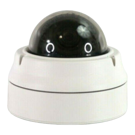
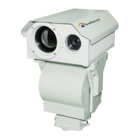
VISUALINT VI-7200S User manual

VI-7200S
Installation Guide

INFORMATIONTOUSER
CAUTION
RISKOFELECTRICSHOCK,
DONOTOPEN
CAUTION:TOREDUCETHERISKOFELECTRICSHOCK,
DONOTREMOVECOVER(ORBACK).
NOUSERSERVICEABLEPARTSINSIDE.
REFERSERVICINGTOQUALIFIEDSEERIVCEPERSONEL.
This symbol is intended to alert the user to the presence of uninsulated
“dangerousvoltage”withintheproduct’senclosurethatmaybeofsufficient
magnitudetoconstituteariskofelectricshocktopersons.
This symbol is intended to alert the user to the presence of important
operatingand maintenance (servicing) instructions in the literature
accompanyingtheappliance.
!
!

VI7200SinstallationGuide
01A.04 3
Table of Contents
1.FEATURES..............................................................................................................4
2.PACKAGECONTENTS..............................................................................................5
3.PARTNAMES.........................................................................................................6
4.INSTALLATION.......................................................................................................8
4.1.InstallationTemplate.........................................................................................................9
4.2.SettingtheImageAttribute................................................................................................9
4.3.OperatingtheOSDMenu..................................................................................................10
5.CONNECTIONS.....................................................................................................11
5.1.Connectors........................................................................................................................11
6.CONFIGURATION.................................................................................................14
6.1.Setupnetworkenvironment............................................................................................14
6.2.Viewvideoonwebpage..................................................................................................14
6.2.1.ViewvideousingIPAdminTool.................................................................................14
6.2.2.ViewvideousingIPaddress......................................................................................16
6.3.Reset................................................................................................................................16
6.4.FactoryDefault.................................................................................................................16
APPENDIX(A):SPECIFICATIONS...............................................................................17
Summary.................................................................................................................................17
ElectricalCharacteristics.........................................................................................................18
EnvironmentCondition...........................................................................................................18
APPENDIX(B):DIMENSIONS....................................................................................19
APPENDIX(C):HEXADECIMALDECIMALCONVERSIONTABLE..................................20
REVISIONHISTORY..................................................................................................21

VI7200SinstallationGuide
01A.04 4
1
1
.
.
F
F
E
E
A
A
T
T
U
U
R
R
E
E
S
S
Camera
•Indoor/OutdoorMiniPTZDomeIPCamera(VandalProof)
•Sony1/4”SuperHADCCD,410KPixel
•x12OpticalZoom,x16DigitalZoom(Maxx192)
•TrueDay&Night(IRCutFilter,DSS)
•360°endlessrotation
•Intelligentpan/tiltcontrolling
•Improvementofcolorrollingsuppression
Streaming
•Dualstreamingmode(suchasdifferentcodec/resolution/bitrateandsoon.)
•DeinterlacingonDSP
•Burntintextsupported
•Unicast/Multicastsupported
Video/Audio
•Videocompression:H.264/MPEG4/MJPEG,25/30FPS@D1(PAL/NTSC)
•Audiocompression:G.711(µLaw,aLaw)/PCM
•Analogvideooutforexternalmonitors
•VideoMotionDetectionsupported
•Twowaymonoaudiosupported
Network
•RTSP/HTTPprotocolsupported
•10/100BaseTEthernet
AdditionalFeatures
•RS485supported
•MicroSDcardsocketforexternalstorage
•OSDsupported
•SDK(SoftwareDevelopmentKit)provided
VCA(VideoContentAnalysis)
•VCAPresence(Includedasbasic)
•VCASurveillance(Optional)

VI7200SinstallationGuide
01A.04 5
2
2
.
.
P
P
A
A
C
C
K
K
A
A
G
G
E
E
C
C
O
O
N
N
T
T
E
E
N
N
T
T
S
S
Unpackcarefullyandhandletheequipmentwithcare.Thepackagingcontains:
Camera
DCpoweradaptor
Terminalblock
InstallationTemplate
Poweradaptorjack
ScrewsandAnchorblocks
VideoBNCcable
Hexwrenchdriver
QuickInstallationGuide
Theabovecontentsaresubjecttochangewithoutpriornotice.
Note
i

VI7200SinstallationGuide
01A.04 6
3
3
.
.
P
P
A
A
R
R
T
T
N
N
A
A
M
M
E
E
S
S
①①
②②
③③
④④
⑤⑤
*Modelshereinandtheirappearance
aresubjecttochangewithoutanyprior
notice.
In
Out
AUDI O DI DO RS-485
12VVout
In Out
AUDIO DI DO RS-485
12V
Vout

VI7200SinstallationGuide
01A.04 7
①MicroSDCardSocket
Itisamemorycardslotforexternalstorage.
②LANConnector(Ethernet)
ThisisaRJ45LANconnectorfor10/100BaseTEthernet.
ThisLEDlightsupasorangeandturnsgreenwhentheencoderispoweredon.
LEDoperationsetting:
For the factory default setting, LED 2 blinks for the heartbeat and LED 1 turns on for video
signal. To change its setting, refer to the section 4.5.11. LED Settingof the NVC Web Page
User’sManual.
③8pinterminalblockforaudio,DI,andDO
Refertothesection“5.1.Connectors”formorespecificinformation.
④6pinconnectorforanalogvideooutput,RS485,andpower
Refertothesection“5.1.Connectors”formorespecificinformation.
⑤Reset
ResetswitchisusedforrestartingthecameraorresettingittoFactoryDefault(FD).Referto
thesection“6.3.Reset”formorespecificinformation.
LED1LED2

VI7200SinstallationGuide
01A.04 8
4
4
.
.
I
I
N
N
S
S
T
T
A
A
L
L
L
L
A
A
T
T
I
I
O
O
N
N
Whenassemblingthemainbodyofthecameraanditsdome
cover,makesure
theyfiteachotherintoplace.
Note
i
1)
Connect the LAN cable, power supply
cable,andthevideoloopoutcablewiththe
camera.
2)
Place the installation template on the
ceiling.
3)
Drillfourholesonthetemplateandinsert
anchor blocks into the holes. Fasten the
surfacemountbracketwithscrews.
4)
Put the main body on the surface mount
bracket of the camera
.Makesurethe
bracket and the main body fit each other
intoplace.
5)
Fastenthemainbodywithscrews.

VI7200SinstallationGuide
01A.04 9
The cameramay fall off the ceiling even after the proper installation and
mounting. To prevent any accident, make sure the ceiling is firm and stable
enough to support the camera. If any reinforcement is needed, consult with
yoursafetypersonnelandproceedwiththeinstallation.
4.1. Installation Template
4.2.Setting the Image Attribute
Caution
!
Installationtemplate
5510V1.0

VI7200SinstallationGuide
01A.04 10
Youcansettheimageattributeofcamerathroughthewebpage.
ThemenuofimageattributecanbeseenunderSetup>Video&Audio>Videoin>Attribute
Setting.Brightness,contrast,hue,saturationandsharpnesscanbeadjusted.
4.3.Operating the OSD Menu
TooperatetheOSDofcamera,refertothe”OSDMenuControlManual.”

VI7200SinstallationGuide
01A.04 11
5
5
.
.
C
C
O
O
N
N
N
N
E
E
C
C
T
T
I
I
O
O
N
N
S
S
5.1.Connectors
①AudioInput/OutputConnection
Connect to the audio input device such as a mike and the audio output device such as the
amplifierspeaker.
AudioInput:Linein,1.43Vpp(Min1.35Vpp,max1.49Vpp),39KΩ
AudioOutput:Lineout,46mWPower,16Ω
②②
③③
④④
⑤⑤
In Out
AUD IO DI DO RS-485
12VVout
In
Out
AUDIO DI DO RS-485
12V
Vout
⑥⑥
①①
AudioInput
AudioOutput
COM
AmplifierSpeaker
MIC

VI7200SinstallationGuide
01A.04 12
Donotconnectthespeakerwithoutamplifier.
②Sensor(DI)connection
Thecameraprovides1channelD/I.Itcanbeconnectedtoeitheravoltagetypesensorora
relaytypesensorasthefollowingfigures.Itcanbeselectedbysoftware.
Inputvoltagerange:0VDCminimumto5VDCmaximum,Max50mA
Inputvoltagethreshold:4.5V
Donotexceedthemaximuminputvoltageorrelayrate.
③Alarm(DO)connection
Thecameraprovides1channelD/O.
RelayRating:Max24VAC500mAor12VDC1A
Donotexceedthemaximumrelayrating.
Caution
!
Caution
!
Caution
!
+5V
DI
COM
DI
COM
+
RelayTypeVoltageType
+
Outputof
Sensor
Outputof
Sensor
Internal
Internal
+

VI7200SinstallationGuide
01A.04 13
④Analogvideoout
ConnectwithBNCcoaxialcable.
⑤RS485Communication
ForPTZcontrol,connectthislinetokeyboard.
⑥PowerConnection
Please,checkthevoltageandcurrentcapacityofratedpowercarefully.
RatedPower
InputVoltageRange
CurrentConsumption
DC12V
DC10.8V~13.2V
1.4A
DO
COM
RelayType
Device
Internal

VI7200SinstallationGuide
01A.04 14
6
6
.
.
C
C
O
O
N
N
F
F
I
I
G
G
U
U
R
R
A
A
T
T
I
I
O
O
N
N
6.1.Set up network environment
ThedefaultIPaddressofyourIPdeviceis192.168.XXX.XXX.YoucanfindtheavailableIPaddress
fromtheMACaddressofyourdevice.PleasemakesurethedeviceandyourPCareonthesame
networksegmentbeforerunningtheinstallation.IfthenetworksegmentbetweenyourPCand
thedeviceisdifferent,changeyourPC’ssettingsasbelow.
IPaddress:192.168.xxx.xxx
Subnetmask:255.255.0.0
6.2. View video on web page
View the live video on a web page using your IP device and its IP address. You can use the
IPAdminToolorentertheIPaddressonthewebpage.
6.2.1. View video using IPAdmin Tool
IPAdminToolautomaticallysearchesallactivatednetworkencodersandIPcamerasandshows
theproductname,IPaddress,MACaddressandetc.

VI7200SinstallationGuide
01A.04 15
TousetheIPAdminToolandviewthelivevideoonawebpage:
1. StartIPAdminTool.Namesandinfoofcurrentlyactivateddevicesappearasalist.
2. RightclickonthedesireddeviceandselectWebview.
3. Clickpopup blockedand install the ActiveX setup.exeby clicking theRun orSave
button.YouneedtoinstalltheActiveXfordisplayingtheimages.
4. Followtheinstructionsofthedialogboxesandcompletetheinstallation.Thenthelive
videoisdisplayedonthemainpageofthewebbrowser.
5. If the live video is not displayed with the message said, “This software requires the
Microsoft XML Parser V6 or higher. Please downloadMSXML6 from the Microsoft
websitetocontinue.Errorcode:CannotcreateXMLDOMDocument.”,pleasedownload
andinstalltherelevantMSXML.
If the ActiveX setup.exefile fails to be installed successfully, close all of the
InternetExplorerwindowsandgotoProgramFiles>AxInstallfolderonyour
computer.Then,runUninstall.exeandtrytoperformthesteps1to4above
again.
Note
i

VI7200SinstallationGuide
01A.04 16
6.2.2. View video using IP address
ViewthelivevideoonawebpageusingyourIPdeviceanditsIPaddress.Tohavethecorrect
IPaddressreadyanduseitonawebpage:
1. ConvertaMACaddresstoanIPaddressorchecktheIPaddressontheIPAdminTool.Referto
Appendix(C):HexadecimalDecimalConversionTable.
(TheMACaddressisattachedonthesideorbottomofthedevice.)
2. OpenawebbrowserandentertheIPaddressofthedevice.
3. Click popupblockedandinstallthe ActiveXsetup.exeby clicking theRunorSavebutton.
YouneedtoinstalltheActiveXfordisplayingtheimages.
4. Followtheinstructionsofthedialogboxesandcompletetheinstallation.Thenthelivevideo
isdisplayedonthemainpageofthewebbrowser.
6.3. Reset
1. Whilethedeviceisinuse,pressandholdtheResetbutton.
2. ReleasetheResetbuttonafter3seconds.
3. Waitforthesystemtoreboot.
6.4. Factory Default
1. Disconnectthepowersupplyfromthedevice.
2. ConnectthepowertothedevicewiththeResetbuttonpressedandheld.
3. ReleasetheResetbuttonafter5seconds.
4. Waitforthesystemtoreboot.
Thefactorydefaultsettingscanbeinferredasfollows:
MACaddress=0013230114B1→IPaddress=192.168.20.177
theHexadecimalnumbertoDecimalnumber.
IPaddress: 192.168.xx.yy
Networkmask:
255.255.0.0
Gateway:
192.168.0.1
UserID:
root
Password:
pass

VI7200SinstallationGuide
01A.04 17
A
A
P
P
P
P
E
E
N
N
D
D
I
I
X
X
(
(
A
A
)
)
:
:
S
S
P
P
E
E
C
C
I
I
F
F
I
I
C
C
A
A
T
T
I
I
O
O
N
N
S
S
Summary
CameraModule
ImageSensor
Sony1/4”SuperHADCCD
EffectivePixels
811x508(NTSC)/795x596(PAL)
TVSystem
NTSC/PAL
HorizontalResolution
580TVL(Color),680TVL(B/W)
Zoom
X12OpticalZoom,x16DigitalZoom
Focallength
F1.67~1.88,f=3.94~46.05mm
SyncSystem
Internal(12VDC)
Min.Illumination
0.7Lux(Color)/0.02Lux(B/W),50IRE
Lens
10XOpticalDay&NightF1.8f=3.8~38.0mm
Iris
Auto/Manual
Day&Night
Auto/Day/Night(ICR)
S/NRatio
52dB
BLC
On/Off
Flickerless
On/Off
SSNR
Yes
Dome
PanAngle/Speed
360°EndlessRotation,
Manual:0.05°~150°/sec/Preset:Max250°/sec
TiltAngle/Speed
2°~90°,
Manual:0.05°~150°/sec/Preset:Max250°/sec
AutoScan
ProgrammableAutoscan
Pattern
8ProgrammablePatterns(total480seconds)
Sector
8selectableSectorswith16characters
OnScreenDisplay
Yes
Video
Compression
H.264,MPEG4,MJPEGSelectableperStream
NumberofStreams
Dualstream,Configurable
Resolution
D1,4CIF,2CIF,VGA,CIF,QCIF,QVGA
CompressionFPS
25/30fps@D1(PAL/NTSC)
Deinterlacing
Support(DSP)
MotionDetection
Support
BurntinText(digital)
Support(DSP)
AnalogVideoOutput
1LoopOut(TerminalBlock)
Audio

VI7200SinstallationGuide
01A.04 18
Input/Output
1/1Ch
Compression
PCM,G.711
Function
Network
10/100BaseT
DI/DO
1/1Ch
RS485
Support
Protocol
TCP/IP,UDP/IP,HTTP,RTSP,RTCP,RTP/UDP,RTP/TCP,
SNTP,mDNS,UPnP,SMTP,IGMP,DHCP,
FTP,DDNS,SSLv2/v3,IEEE802.1X,SNMPv2/v3
SDmemory
MicroSDcardslot
※
MicroSDCardisnotincluded
Mechanical
Material
AluminumDieCasting/Polycarbonate
Dimensions
Housing:Housing:157(Ф)x178(H)mm
Color
Ivory
Weight
1,900g
Electrical Characteristics
PowerSource
12VDC
PowerConsumption
(Approx.)
1400mA
AnalogVideoOutput
1Vpp,75Ω,Composite
AudioInput
Linein,1.43Vpp(Min1.35Vpp,max1.49Vpp),39KΩ
AudioOutput
Lineout,46mWPower,16Ω
Sensor(D/I)
Max50mA@5VDC,TTLlevel4.5Vthreshold
Alarm(D/O)
Max500mA@24VACor1A@12VDC
Onstateresistance:50Ω(maxcontinuous)
Environment Condition
OperatingTemperature
OperatingRange
DC12V:40˚C~50˚C(40˚F~122˚F)
ColdStart
DC12V:10˚C(14˚F)
StorageTemperature 20°C~60°C(4°F~140°F)
OperatingHumidityUpto85%RH

VI7200SinstallationGuide
01A.04 19
A
A
P
P
P
P
E
E
N
N
D
D
I
I
X
X
(
(
B
B
)
)
:
:
D
D
I
I
M
M
E
E
N
N
S
S
I
I
O
O
N
N
S
S
(Unit:mm)

VI7200SinstallationGuide
01A.04 20
A
A
P
P
P
P
E
E
N
N
D
D
I
I
X
X
(
(
C
C
)
)
:
:
H
H
E
E
X
X
A
A
D
D
E
E
C
C
I
I
M
M
A
A
L
L
-
-
D
D
E
E
C
C
I
I
M
M
A
A
L
L
C
C
O
O
N
N
V
V
E
E
R
R
S
S
I
I
O
O
N
N
T
T
A
A
B
B
L
L
E
E
RefertothefollowingtablewhenyouconverttheMACaddressofyourdevicetoIPaddress.
Hex
Dec
00
0
01
1
02
2
03
3
04
4
05
5
06
6
07
7
08
8
09
9
0A
10
0B
11
0C
12
0D
13
0E
14
0F
15
10
16
11
17
12
18
13
19
14
20
15
21
16
22
17
23
18
24
19
25
1A
26
1B
27
1C
28
1D
29
1E
30
1F
31
20
32
21
33
22
34
23
35
24
36
Hex
Dec
25
37
26
38
27
39
28
40
29
41
2A
42
2B
43
2C
44
2D
45
2E
46
2F
47
30
48
31
49
32
50
33
51
34
52
35
53
36
54
37
55
38
56
39
57
3A
58
3B
59
3C
60
3D
61
3E
62
3F
63
40
64
41
65
42
66
43
67
44
68
45
69
46
70
47
71
48
72
49
73
Hex
Dec
4A
74
4B
75
4C
76
4D
77
4E
78
4F
79
50
80
51
81
52
82
53
83
54
84
55
85
56
86
57
87
58
88
59
89
5A
90
5B
91
5C
92
5D
93
5E
94
5F
95
60
96
61
97
62
98
63
99
64
100
65
101
66
102
67
103
68
104
69
105
6A
106
6B
107
6C
108
6D
109
6E
110
Hex
Dec
6F
111
70
112
71
113
72
114
73
115
74
116
75
117
76
118
77
119
78
120
79
121
7A
122
7B
123
7C
124
7D
125
7E
126
7F
127
80
128
81
129
82
130
83
131
84
132
85
133
86
134
87
135
88
136
89
137
8A
138
8B
139
8C
140
8D
141
8E
142
8F
143
90
144
91
145
92
146
93
147
Hex
Dec
94
148
95
149
96
150
97
151
98
152
99
153
9A
154
9B
155
9C
156
9D
157
9E
158
9F
159
A0
160
A1
161
A2
162
A3
163
A4
164
A5
165
A6
166
A7
167
A8
168
A9
169
AA
170
AB
171
AC
172
AD
173
AE
174
AF
175
B0
176
B1
177
B2
178
B3
179
B4
180
B5
181
B6
182
B7
183
B8
184
Hex
Dec
DE
222
DF
223
E0
224
E1
225
E2
226
E3
227
E4
228
E5
229
E6
230
E7
231
E8
232
E9
233
EA
234
EB
235
EC
236
ED
237
EE
238
EF
239
F0
240
F1
241
F2
242
F3
243
F4
244
F5
245
F6
246
F7
247
F8
248
F9
249
FA
250
FB
251
FC
252
FD
253
FE
254
FF
255
Hex
Dec
B9
185
BA
186
BB
187
BC
188
BD
189
BE
190
BF
191
C0
192
C1
193
C2
194
C3
195
C4
196
C5
197
C6
198
C7
199
C8
200
C9
201
CA
202
CB
203
CC
204
CD
205
CE
206
CF
207
D0
208
D1
209
D2
210
D3
211
D4
212
D5
213
D6
214
D7
215
D8
216
D9
217
DA
218
DB
219
DC
220
DD
221
Table of contents
Other VISUALINT Security Camera manuals

