Vita Mobility Werks V7x User manual

www.vitamobilitywerks.com
1
USER MANUAL
VITA MOBILITY WERKS
V7x
www.vitamobilitywerks.com
2
SAFETY INSTRUCTION
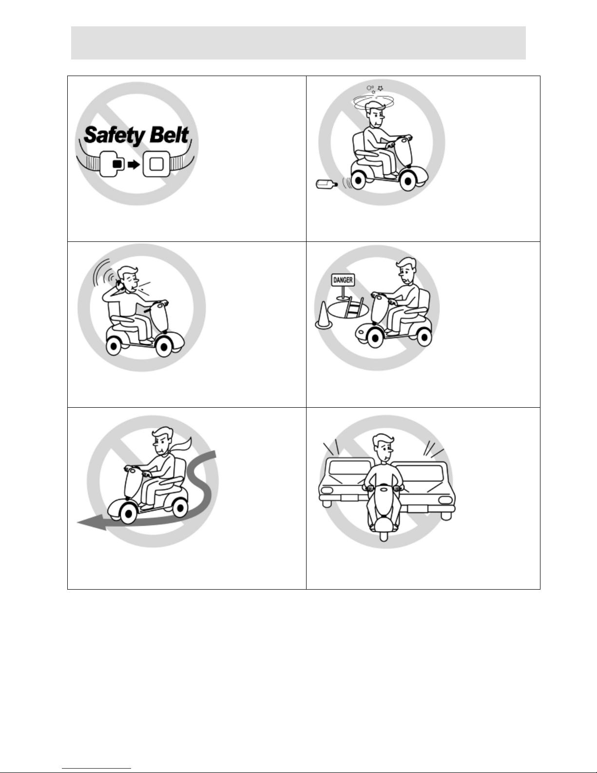
!General
Always use a seat belt, and keep your feet on the
scooter all the time.
Never operate the scooter while you are under the
influence of alcohol.
Never use electronic radio transmitters such as
walkie-talkies, or cellular phones.
Make sure that there are no obstacles behind you
while reserving your scooter.
Do not make a sharp turn or a sudden stop while
riding your scooter.
Do not ride your scooter in traffic.
www.vitamobilitywerks.com
3
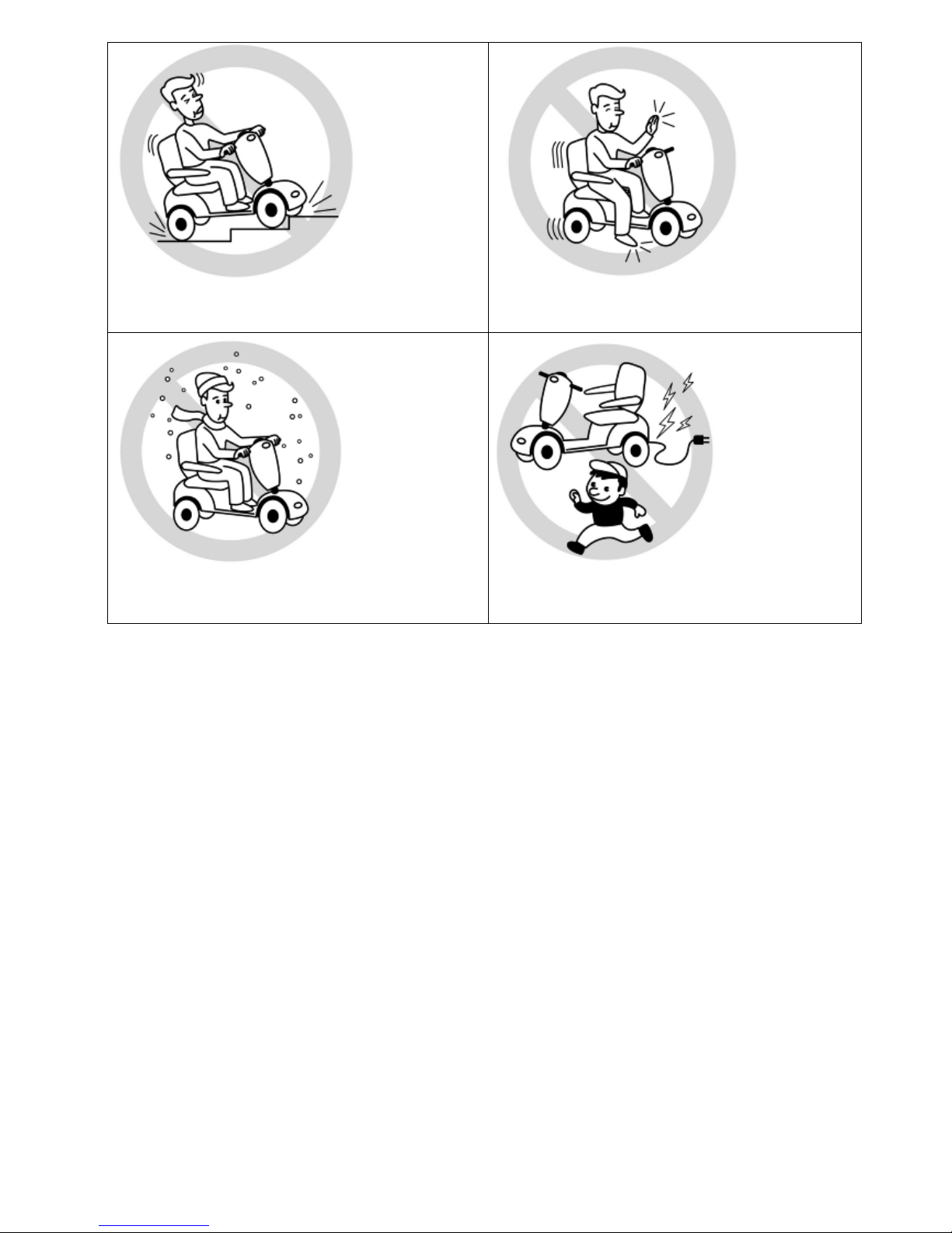
Do not attempt to climb curbs greater than
limitation show on Technical Specification
Do not leave your hands and legs off the scooter
when driving.
Do not ride your scooter during snow in order to
avoid accident on slippery road.
Do not allow unsupervised children to play near
this equipment while the batteries are charging.
!Warning – Don’t operate your scooter for the first time without completely reading and
understanding this user manual.
1. Don’t operate scooter on public streets and roadways. Be aware that it may be difficult for traffic
to see you when you are seated on the scooter. Obey all local pedestrian traffic rules. Wait until
your path is clear of traffic, and then proceed with extreme cautions.
2. To prevent injury to yourself or others, always ensure that the power is switched off when getting
on or off of the scooter.
3. Always check that the drive wheels are engaged (drive mode) before driving. Do not switch off
the power when the scooter is still moving forward. This will bring the chair to an extremely
abrupt stop.
4. Do not use this product or any available optional equipment without first completely reading and
understanding these instructions. If you are unable to understand the warnings, cautions or
instructions, contact a healthcare professional, the dealers or technical supports before attempting
to use this equipment, otherwise, injury or damage may occur.

www.vitamobilitywerks.com
4
5. There are certain situations, including some medical conditions, where the scooter user will need
to practice operating the scooter in the presence of a trained attendant. A trained attendant can be
defined as a family member or care professional especially trained in assisting a scooter user in
various daily living activities. Consult with your physician if you are taking any medication that
may affect your ability to operate your scooter safely.
6. Do not attempt to lift or move a power scooter by any of its removable parts including the
armrests, seats or shrouds. Personal injury and damage to the power chair may result.
7. Never try to use your scooter beyond its limitations as described in this manual.
8. Please do not sit on your scooter while it is in a moving vehicle.
9. Keep your hands away from the wheels (tires) while driving scooters. Be aware that loose fitting
clothing can become caught in the drive tires.
10. Consult your physician if you are taking prescribed medication or if you have any certain
physical limitations. Some medications and limitations may impair your ability to operate
scooters in a safe manner.
11. Be aware when the drive mode is unlocked or locked.
12. Don’t remove anti-tipper if there is any-tipper equipped with the scooter.
13. Contact with tools can cause electrical shock and do not connect an extension cord to the AC/DC
converter or the battery charger.
14. Do not attempt to lift or move your scooter by any of its removal parts, such as the armrests,
seats, or shroud.
15. When climbing an incline, don’t drive at an angle up the face of the incline. Drive your scooter
straight up the incline. This greatly reduces the possibility of a tip or a fall.
16. Don’t climb a slope steeper than the scooter’s limitation.
17. Don’t attempt to have your scooter proceed backward down any step, curb or other obstacle. This
may cause the scooter to fall or tip.
18. Always reduce your speed and maintain a stable center of gravity when cornering sharply. Don’t
corner sharply when driving scooters at higher speeds.
19. Operating in rain, snow, salt, mist conditions and on icy or slippery surfaces may have an adverse
affect on the electrical system.
20. Never sit on your scooter when it is being used in connection with any type of lift or elevation
product. Your scooter is not designed with such use in mind and any damage or injury incurred
from such use is not the responsibility of VMW

www.vitamobilitywerks.com
5
!Modifications
VMW Medical Product has designed and engineered power scooters to provide maximum utility.
However, under no circumstances should you modify, add, remove, or disable any part or function of
your power scooter. Personal injury and damage to the power chair may result.
1. Do not modify your power scooter in any way not authorized by VMW. Do not use accessories if
they have not been tested or approved for VMW products.
2. Get to know the feel of your power scooter and its capabilities. VMW recommends that you
perform a safety check before each use to make sure your scooter operates safely.
!Inspections prior to using your power scooter:
1. If equipped with pneumatic tires, please check for proper tire inflations.
2. Please check all electrical connections and make sure they are tight and not corroded.
3. Please check all harness connections and make sure they are secured properly.
4. Please check the brakes.
!Weight limitation.
1. Please refer to the specifications table for weight capacity information. Power scooter is rated for a
maximum weight capacity.
2. Stay within the specified weight capacity for your scooter. Exceeding the weight capacity voids
your warranty. VMW will not be held responsible for injuries or property damage resulting from
failure to observe weight limitations.
3. Don’t carry passengers on scooters. Carrying passengers on scooter may affect the center of
gravity, resulting in a tip or a fall.
!Tire inflation
1. If your scooter is equipped with pneumatic tires, it is necessary to check the air pressure at least
one time a week.
2. Proper inflation pressures will prolong the life your tires and ensure the smooth operation while
riding.
3. Do not under-inflate or over-inflate your tires. It is critically important that 30-25 psi (2-2.4bar)
tire pressure be maintained in pneumatic tires at all times.
4. Inflating your tires from an unregulated air source could over-inflate them, resulting in a burs
tire.

www.vitamobilitywerks.com
6
!Temperature
1. Some of the parts of the power scooter are susceptible to change in temperature. The controller
can only operate in temperature that ranges between -25 ~ 50.
2. At extreme low temperatures, the batteries may freeze, and your power scooter may not be able
to operate. In extreme high temperatures, it may operate at slower speeds due to a safety feature
of the controller that prevents damage to the motors and other electrical components.
ELECTROMAGNETIC INTERFERENCE (EMI)
The rapid development of electronics, especially in the area of communications, has saturated our
environment with electromagnetic (EM) radio waves that are emitted by television, radio and
communication signals. These EM wave are invisible and their strength increases as one approach the
source. All electrical conductors act as antennas to the EM signals and, to varying degrees, all power
wheelchairs and scooters are susceptible to electromagnetic interference (EMI). The interference
could result in abnormal, unintentional movement and/or erratic control of the vehicle. The United
States Food and drug Administration (FDA) suggests that the following statement be incorporated to
the user’s manual for all power scooter like the v7x. Power scooters may as susceptible to
electromagnetic interference (EMI), which is interfering electromagnetic energy emitted from sources
such as radio stations, TV stations, amateur radio (HAN) transmitter, two-way radios, cellular phones
and alarm systems of shops. The interference (from radio wave sources) can cause the power scooter
to release its brakes, move by itself or move in unintended directions. It can also permanently damage
the powered scooter’s control system. The intensity of the EM energy can be measured in volts per
meter (V/m).Each powered scooter can resist EMI up to a certain intensity. This is called “immunity
level”. The higher the immunity level the greater the protection. At this time, current technology is
capable of providing at least 20 V/m of immunity level, which would provide useful protection
against common sources of radiated EMI.
Following the warnings listed below should reduce the chance of unintended brake release or powered
scooter movement that could result in serious injury:
1. Do not turn on hand-held personal communication devices such as citizens band (CB) radios and
cellular phones while the powered scooter is turned on.
2. Be aware of nearby transmitters such as radio or TV stations and try to avoid coming close to
them.

www.vitamobilitywerks.com
7
3. If unintended movement or brake release occurs, turn the powered scooter off as soon as it is
safe.
4. Be aware that adding accessories or components, or modifying the powered scooter, may make it
more susceptible to interference from radio wave sources (Note: It is difficult to evaluate the
effect on the overall immunity of the powered scooter).
5. Report all incidents of unintended movement or brake release to the powered scooter
manufacturer, and note whether there is a radio wave source nearby.
TURN OFF YOUR POWERED SCOOTER AS SOON AS POSSIBLE WHEN EXPERIENCING
THE FOLLOWING:
"Unintentional scooter movements
"Unintended or uncontrollable direction.
"Unexpected brake release
The FDA has written to the manufacturers of power scooters asking them to test new products to be
sure they provide a reasonable degree of immunity against EMI. The FDA requires that a powered
wheelchair should have an immunity level at least 20 V/m, which provides a reasonable degree of
protection against more common sources of EMI. The higher the immunity level the greater the
protection. Your powered scooter has an immunity level of 20 V/m which should protect against
common sources of EMI. Warning: The scooter itself can disturb the performance of the
electromagnetic fields such as emitted by alarm systems of shops.

www.vitamobilitywerks.com
8
TECHNICAL SPECIFICATIONS
MODEL
V7x
WEIGHT CAPACITY
160kgs(350 lbs)
SEAT: TYPE/SIZE
20"
DRIVE WHEEL
410mmx100mm(16"x4")
FRONT CASTER (WHEEL)
360mmx90mm(14"x3.5")
REAR CASTER (ANTI-TIPPER)
-
MAX SPEED
14 KM/H ~ 15 KM/H
BATTERY SPECIFICATIONS
12V 80Ah x 2pcs
BATTERY RANGE
50km(31 miles)
CHARGER TYPE
8Amp,Off Board 120/240 Volt, 50/60Hz
CONTROLLER TYPE
S-DRIVE 200Amp
MOTOR TYPE
1300W 4-Pole Motor
WEIGHT: W/ BATTERY
151KG
WEIGHT: W/O BATTERY
101KG
TURNING RADIUS
1600mm (63")
SUSPENSION
Full
LENGTH
1580mm(62")
WIDTH
730mm(29")
HEIGHT
1350mm(53")
SEAT WIDTH
508mm(20")
SEAT HEIGHT
711mm(28")
SEAT DEPTH
460mm(18")
BACK HEIGHT
698mm(27.5")
WHEEL BASE
1000mm(39")
GROUND CLEARANCE
150mm(6")
FOOTRESTS
460mm(18")
www.vitamobilitywerks.com
9
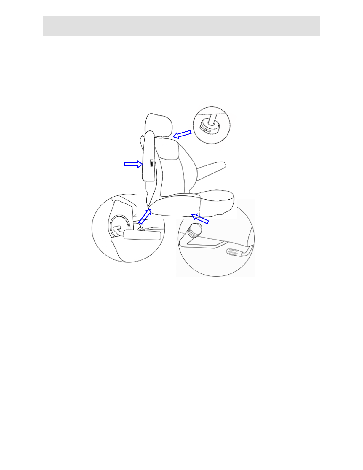
COMFORT ADJUSTMENT
Adjustments for Seating Comfort:
Press the bottom to adjust
the height of the headrest.
Adjust the seat back lever
for seating back angle.
The flip-up armrest height
can be adjusted by turning
the adjustment dial.
#Turn the swivel lever downwards to rotate the seat.
#Push the front lever upwards to move the seat forward
and backward.

www.vitamobilitywerks.com
10
OPERATION OF CONTROL PANEL
Function Descriptions
FUNCTION
SPECIFICATION
1
Speed Sensor
7 Segment display (2.5 digits +1 decimal) + “km/h / mph” symbol
2
High / Low / Turn
Speed
Indicated as “H” and “L” symbols
3
Power Indicator
Battery remaining capacity and charging indicator
(6 squares + Battery Icon)
4
Clock
Hour / Minute / Second display and setting
5
Odometer
ODO (99999 km max), TRIP (99.9 max)
6
Main-Beam
(Headlight)
“Power-saving” mode, Blue LED
7
Back-up Lamps
“Brake / Reverse” modes, Orange LED
8
Right-Indicator
Flash mode, Green LED
9
Left-Indicator
Flash mode, Green LED
10
Parking Lamp
Including “Reverse Mode”, left- indicator and right-indicator flashing
simultaneously, Red LED
11
Malfunction
Message
Malfunction code:
7 Segment display (1digit ) + Warning symbol + Red LED
12
Power-on Scan
All LED turn on
13
Temperature
(TEMP) Gauge
“°C / °F” modes
14
Reverse Light
“Reverse” symbol flashing

www.vitamobilitywerks.com
11
2-2 Button & LED
FUNCTION
SPECIFICATION
Buttons
“MODE” switch
Function set
Left-Indicator
control
Right-Indicator control
Parking Light
control
Headlight control
High / Low speed
switch
Back-up lamps control
Horn
LED Indicators
Left-Indicator
(Green)
Right- Indicator (Green)
Parking (Red)
Headlight (Blue)
Warning (Red)
Back-up lamp (Amber)
LCD Backlight
Illumination: 700 mcd min (Orange color)
LOGO Backlight
Blue color
Connecter
CON1: 20PIN
3. Usage Conditions
ITEM
SPECIFICATION
Voltage
DC 24 V
Operation Voltage
DC 16 ~32 V
Storage Temperature
-40°C ~ 90°C
Operation Temperature
-25°C ~ 55°C
Meter Angle
at Handle Cover
30°of elevation while scooter assembly
(LCD orientate to six o’clock)
SE
T
M
O
D
E

www.vitamobilitywerks.com
12
4. Characteristics Test
General Characteristic Performance Test (20 ±5)
Hardware Circuit:
ITEM
SPECIFICATION
RESULT (n = )
Lowest Operation
Voltage
16V max
V
Consuming Current
(VB = 24.0V)
Dynamic: 200 mA max
-- Backlight and LED light status
Static: 5 mA max
-- Key OFF status
mA
mA
5. OPERATING INSTRUCTION
5-1. Speed Sensor and Display
ITEM
SPECIFICATION
Operation Features
Speed detection by speed sensor from transaxle with conversion at
1400rpm equal to 60km/h.
Tolerance
15~20%
Digits range
≤19.9: 0~19.9
> 19.9: displayed by integer “20~199” (199 max)
Display Switch Button
Initial setting at km/h, switch to MPH by MODE and SET buttons
www.vitamobilitywerks.com
13
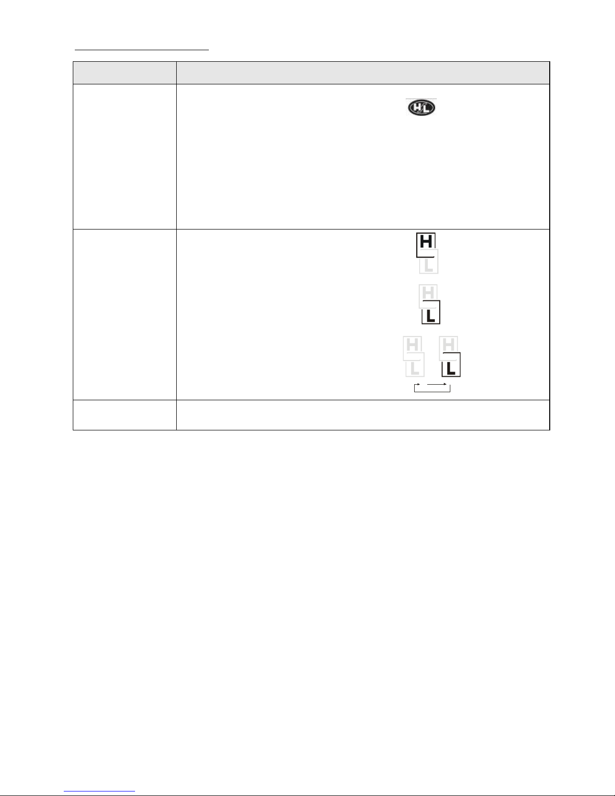
5-2. High / Low / Turn Speed
ITEM
SPECIFICATION
Operation Features
(1) Switch High / Low speed by pressing button once.
(TRN as control signals)
Press one time: High-speed <<--->> Low-speed
(with memory storage).
(2) Take exterior turn-switch as determinant signal
(TRN as control signals).
Symbols on LCD
"H"symbol means “High Speed”:
SPEED
"L"symbol means “Low Speed”:
SPEED
"L"symbol flashing means “Turn Speed”:
SPEED SPEED
Flicker Frequency
1 sec.
www.vitamobilitywerks.com
14
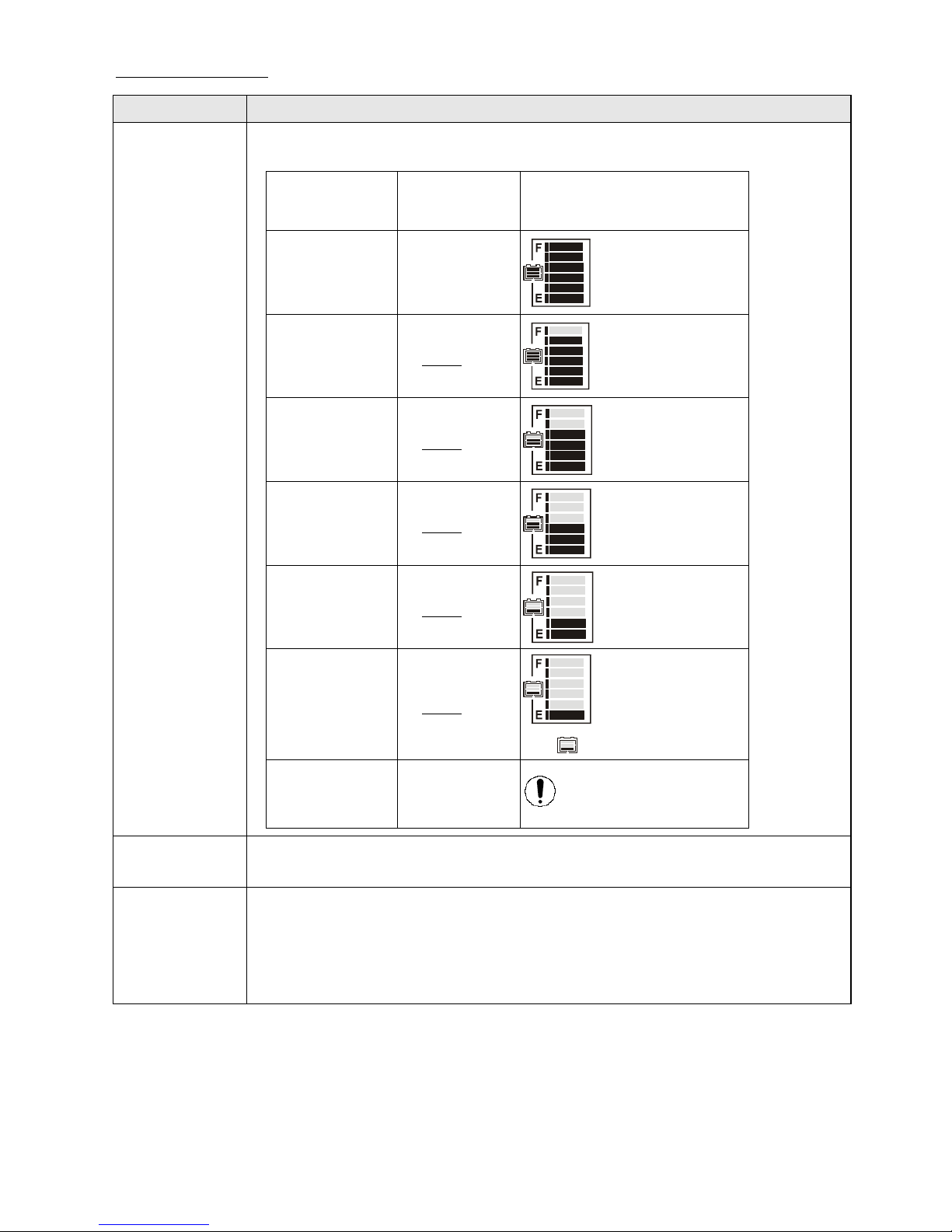
5-3. Power Indication
ITEM
SPECIFICATION
Battery
Remaining
Capacity
Remaining
Capacity (%)
Voltage (V)
Scale Bar
100
(6)
>25.42
85
(5)
25.42
70
(4)
25.12
55
(3)
24.78
40
(2)
24.42
30
(1)
23.88
and Flashing
20
Low-power
Warning
Warning LED Flashing
Flicker
Frequency
2 sec.
Operation
Characters
(1) Scale status only decrease, won’t increase.
(2) When the remaining capacity was less than 30%, warning sound (“Be-Be”
two short sounds) act at 5 seconds intervals.
While (a) Key Off (b) Charging Mode (c) Sleep Mode, warning sound
released.

www.vitamobilitywerks.com
15
ITEM
SPECIFICATION
Charge
Indication
Remaining
Capacity (%)
Voltage
(V)
Scale Bar
40
(2)
<25.44
55
(3)
>25.44
70
(4)
>26.18
80
(5)
>26.92
90
(6)
>28.5
100
(7)
Increase
Frequency
0.5 sec.
Operation
Character
(1) Scale status only decrease, won’t increase.
(2) Take the PIN3(CH3) of charger as determinant signal, enter「Charging
Mode」when CH3 grounding (L), not only “KEY ON” or “KEY OFF”.
Remarks
Above scale bar status only for reference, must take the indicator of charger
as the precise diagnosis.

www.vitamobilitywerks.com
16
5-4. Clock
ITEM
SPECIFICATION
Tolerance (per day)
±2 sec.
Initial Setting Value
『Hour:Min』mode :『AM 12:00』
『Hour : Min』Setting
(12-Hour format)
Display range : AM12:00 ~ PM11:59
AM
PM
:
mi l e
km
When『Hour』is between 1 and 9 o’clock, displayed at 1~9.
5-5. Odometer
ITEM
SPECIFICATION
Operation Features
Odometer detected by the signal of Opto Coupler then converts into distance.
Display Switch
Button
「km/h」means the odometer displayed as kilometer.
「mph」means the odometer displayed as mile.
Accumulative
Display [ODO]
(1) Display Range:00000~99999
AM
PM
:
mi l e
km
(2) Once the total mileage up to 99999km or 62149mile (99999÷1.609mile), the
counter will restart from “00000”.
TRIP Counter
(1) Display Range:00.0~99.9
AM
PM
:
mi l e
km
(2) When over 99.9km, display stop counting
(won’t restart from “00.0”).
Operation status
(1) Odometer indication display on ODO mode when Power On, then switch
to TRIP mode after 5 seconds.
(2) TRIP can be reset to “00.0”.

www.vitamobilitywerks.com
17
5-6. Headlight Control
ITEM
SPECIFICATION
Operation Feature
Take exterior headlight switch as determinant signal.
(1) Switch on/off the head light by pressing button once, then
LED will turn on/off simultaneously.
(2) LCD backlights turn on / turn off with head light.
Power Saving Mode
When motor stop, the modulation down to 30% (Headlight)
When motor act, 100% output power (Headlight)
Usage Condition
While (a) KEY OFF (b) Power-Saving mode (c) Sleep mode , all functions
closed.
Determinant
Condition
(1) 2.2V>WIP>2.8V ( 100% Full-power )
(2) 2.2V<WIP>2.8V ( 100% Full-power )
(3) Full / Half power switch at real time.
(4) The determination of “Reversing Mode” need to consider the motor
direction and panel setting.
Remarks
(1) Loop Load: 24V/50W max
(2) With “short circuit” and “overload” protection

www.vitamobilitywerks.com
18
5-7. Back-up Lamp Control
ITEM
SPECIFICATION
Operation Feature
Take exterior back-up lamp switch as determinant signal.
(1) Switch on/off the head light by pressing button once, then
LED will turn on/off simultaneously.
(2) LCD backlights turn on / turn off with head light.
(Control Mode)
Brake-lamp Mode
Reversing-lamp Mode
When motor changes from act (go forward) to stop, the lamp reinstated
after flashing for 3 sec.
Determine as “Reversing Mode”, back-up lamp keep flashing.
Reverse warning sound can be set by panel ( Turn on / Turn off)
Usage Condition
While (a) KEY OFF (b) Charging Mode (c) Sleep Mode, all functions
closed.
* Brake-lamp & Reversing-lamp Mode won’t be limited by Back-up
lamp switch on or off.
Flicker Frequency
1 sec.
Determinant Condition
(1) 2.2V>WIP>2.8V ( 50% Half-power )
(2) 2.2V<WIP>2.8V ( 100% Full-power )
(3) Full / Half power switch at real time.
(4) The determination of “Reversing Mode” need to consider the motor
direction and panel setting.
Remarks
(1) Loop Load : 24V/50W max
(2) With “short circuit” and “overload” protection
www.vitamobilitywerks.com
19
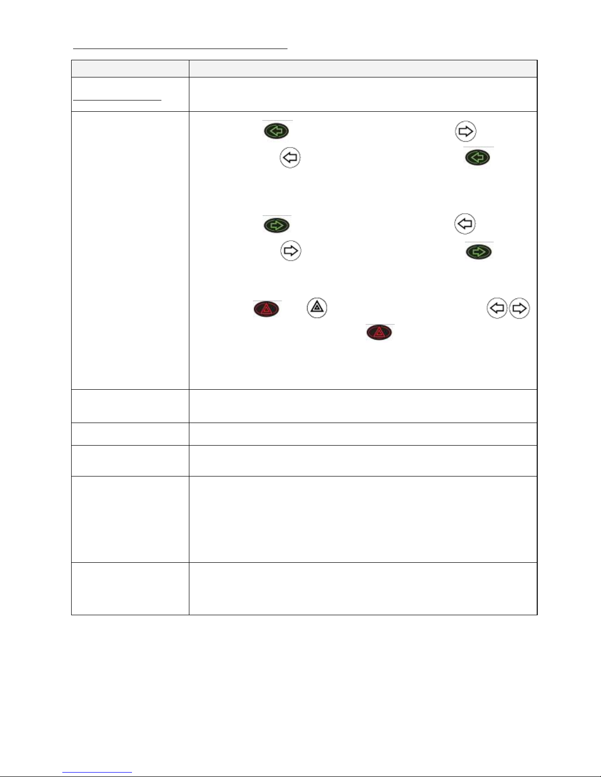
5-8, 9, 10. Indicators and Parking-Lamp Control
ITEM
SPECIFICATION
Operation Feature
Take exterior left-right indicators and parking-lamps switch as the
determinant signal.
Control Mode
(Left-direction lamp)
(Right-direction lamp)
(Parking lamp)
Press button once, the right-indicator and turn off,
left-indicator and flashing, warning sound act. Press again to
turn off left-indicator.
Press button once, the right-indicator and turn off,
left-indicator and flashing, warning sound act. Press again to
turn off left-indicator.
Press button once, turn on, right-left indicators and
flashing , warning sound act . Press again to turn off the Parking
lamp function.
Usage Condition
While (a) KEY OFF (b) Charging Mode (c) Sleep Mode, all functions
closed.
Flicker Frequency
1 sec.
Warning Sound
Frequency
One short “Bi” sound per second
Determinant Condition
Left-Right indicators have priority to Parking lamp.
<Ex.>
If “Parking lamp” turned on already, now you start “Right indicator”
function, the flashing indicator lamps will change from both side (left &
right) to right side, and the “Parking lamp” function will be closed.
Remarks
(1) Load circuit for left-direction light: 24V/50W max
(2) Load circuit for right-direction light: 24V/50W max
(3) With “short circuit” and “overload” protection
www.vitamobilitywerks.com
20
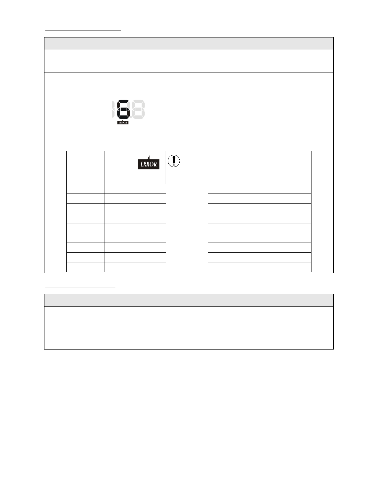
5-11. Malfunction Message
ITEM
SPECIFICATION
Operation Feature
Take the connector pin (KEY) of controller as determinant signal, then
converts it into digital code.
Usage Condition
When the controller send out an error message, red LED flashing with
controller signal at same time, the “Error message code” will show on LCD.
mph km/h
Flicker Frequency
1 sec.
Controller
message
(Flicker)
Message
code
symbol
LED
(Flicker)
Status
1
--
--
Flashing,
opposite to
controller
message.
Battery needs charge soon.
2
2
On
Low-voltage, needs charge now
3
3
On
Over-voltage
4
4
On
Over-current
5
5
On
Park Brake lost or faulted
6
6
On
Accelerator not align center
7
7
On
Accelerator broken or faulted
8
8
On
Motor broken or faulted
9
9
On
Others
5-12. Power On Self Test
ITEM
SPECIFICATION
Initial Status
When scooter power on, the control panel will go through a self-test routine;
the backlight and all LCD segments will be tuned on for 3 seconds, then switch
automatically to the general operation mode (ODO).
Table of contents
Other Vita Mobility Werks Scooter manuals


