To adjust the height, you need to open
the seat clamp’s quick release or unscrew
the screw on the seat clamp with a 4 or
5 mm allen key.
Once the height is adjusted, close the
quick release lever. If necessary, adjust
the tightness level on the opposite nut so
that the lever tightens around midway
through closing.
In the case of a seat clamp with screw,
tighten the screw to the recommended
torque level which is 5 - 6 Nm.
Never go past the recommended
torque level.
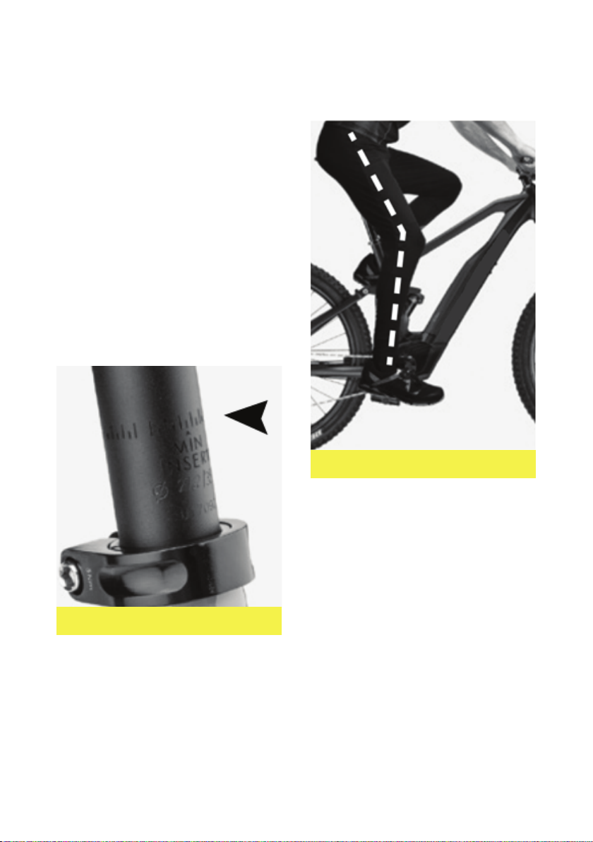
A. SADDLE HEIGHT
The rst set up to carry out on your Zoomo
is the saddle height. Once again, your local
workshop can help you do this.
You must not hesitate to adjust this if you
do not nd the correct height immediately.
We have a good tip to help you nd the
correct setting quickly: position the crank
in line with the seat tube, without being
lopsided on the saddle and place your heel
on the pedal with your leg almost straight.
(see Figure 3)
Never go over the maximum height level
on your seat post marked by the
engraving « INSERT MIN » or « STOP ».
This is for your safety, as well as the
reliability of your bike.
Figure 2. Ideal Post Height.
Figure 3. Minimum insert level seatpost.
RIDING POSITION & BIKE SETUP
INSTALLATION & OPEARTAION INSTRUCTION
INSTRUCTIONS D'INSTALLATION ET DE FONCTIONNEMENT
05