Vital Systems OCTO24 User manual

Octo24 –pn8732
Ethernet PLC / Remote-I/O
User Guide
(Document Revision 3)
(Updated: May 14, 2020)
© 2017 Vital System Inc
Buford, GA USA

Octo24 User’s Guide
www.vitalsystem.com
Ver. 8732doc rev3 © Copyright 2020 Vital System 1 | P a g e
Contents
Overview ..................................................................................................................................................... 3
Operating Specifications ......................................................................................................................... 3
2. Hardware and Wiring.............................................................................................................................. 4
Digital I/O - M12-A Connectors............................................................................................................... 4
Ethernet - M12-D (FEMALE) Connector –Auto MDIX Capable............................................................... 5
PWR - M12-A (MALE) Connector ............................................................................................................ 5
I/O POWER - M12-A (MALE) Connector.................................................................................................. 5
Selecting Power for I/O ........................................................................................................................... 6
Powering Both CPU & Outputs from PWR Plug (MIX)......................................................................... 6
Powering CPU & Outputs Separately Using the PWR & I/O Power Plug (ISO).................................... 6
3. Device Configuration............................................................................................................................... 7
Network Settings..................................................................................................................................... 8
IP Address ............................................................................................................................................ 8
Subnet Mask ........................................................................................................................................ 9
Gateway............................................................................................................................................... 9
Conveyor Settings.................................................................................................................................... 9
Host ID ................................................................................................................................................. 9
Upstream ............................................................................................................................................. 9
Downstream ...................................................................................................................................... 10
Divert Right........................................................................................................................................ 10
Divert Left .......................................................................................................................................... 10
Merge................................................................................................................................................. 10
Miscellaneous Settings.......................................................................................................................... 10
Remote I/O ........................................................................................................................................ 10
CB:14.................................................................................................................................................. 10
CW:15 ................................................................................................................................................ 11
4. Operating Modes .................................................................................................................................. 12
Remote I/O Controller Mode................................................................................................................ 12
Programmable Logic Controller Mode.................................................................................................. 12
Control More than 8 In & 8 Out using one ladder program ................................................................. 12
CPU LED Blink Patterns.......................................................................................................................... 13
5. Network Communication Protocols...................................................................................................... 14
Ethernet/IP Protocol ............................................................................................................................. 14
Input/Produce Message Format (T O).......................................................................................... 16
Output/Consume Message Format (O T) ...................................................................................... 17
Explicit Requests................................................................................................................................ 18

Octo24 User’s Guide
www.vitalsystem.com
Ver. 8732doc rev3 © Copyright 2020 Vital System 2 | P a g e
Modbus / TCP Protocol ......................................................................................................................... 19
S3G-Master/Slave Protocol................................................................................................................... 20
Profinet RT............................................................................................................................................. 21
Import XML Device Profile................................................................................................................. 21
Profinet Ethernet Configuration........................................................................................................ 22
Real Time Settings ............................................................................................................................. 23
I/O Data ............................................................................................................................................. 23
SICK Scanner Protocol ........................................................................................................................... 24
Scanner Configuration....................................................................................................................... 24
Barcode Operation in Superlogic....................................................................................................... 25
6. Programming and Configuring OCTO24 Devices .................................................................................. 27
SuperLogic Pro....................................................................................................................................... 27
Deploy3G............................................................................................................................................... 28
7. Control Words....................................................................................................................................... 29
8. Control Bit File....................................................................................................................................... 31
9. Network Topology Examples ................................................................................................................ 32

Octo24 User’s Guide
www.vitalsystem.com
Ver. 8732doc rev3 © Copyright 2020 Vital System 3 | P a g e
Overview
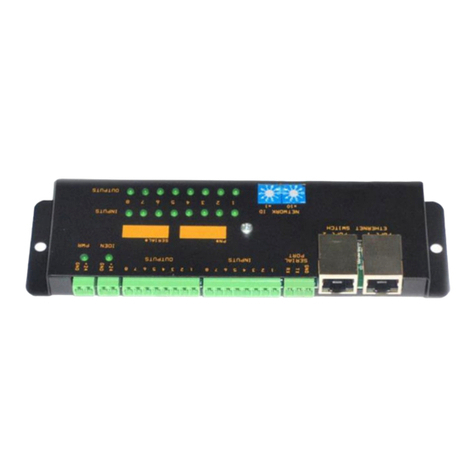
The OCTO24 Smart Ethernet Programmable Controller provides networked 24volts Digital I/O for MDR
Powered Roller Conveyor systems using the G20 ZPA cards, as well as general purpose Fast
Local/Remote Machine I/O. These Devices are fully programmable for any type of control application,
and can act as a programmable master device, or a slaved Remote I/O device. The modules
communicate over Ethernet to master or peer devices using Ethernet/IP, Profinet RT, Modbus TCP and
S3G-Master Slave protocols. For MDR conveyors, interlocking messaging bits e.g., upstream,
downstream, merge, divert, etc are handled by the firmware for simplified Ladder Logic Programming.
Operating Specifications
CPU Input Power
18 –26V DC. Typical 24V, 150 mA
Digital Output Voltage
18 –26V DC
Digital I/O Circuit Type
PNP (Sourcing)
Digital Output Max Current
500 mA per Output, 2A Max per Unit
Digital Inputs Voltage
18 –26V
Network
Ethernet 100Mb/s
Ethernet Switch
2 Ports, Auto-MDIX
IP Rating
IP67

Octo24 User’s Guide
www.vitalsystem.com
Ver. 8732doc rev3 © Copyright 2020 Vital System 4 | P a g e
2. Hardware and Wiring
Label
Connector
Description
1
M12-A Male
Digital Input 1, Output 1
2
M12-A Female
Digital Input 2, Output 2
3
M12-A Male
Digital Input 3, Output 3
4
M12-A Female
Digital Input 4, Output 4
5
M12-A Male
Digital Input 5, Output 5
6
M12-A Female
Digital Input 6, Output 6
7
M12-A Male
Digital Input 7, Output 7
8
M12-A Female
Digital Input 8, Output 8
NET 1
M12-D Female
Ethernet Port1
NET 2
M12-D Female
Ethernet Port2
I/O POWER
M12-A Male
Digital Outputs power Plug.
PWR
M12-A Male
CPU and optional Digital Outputs power Plug.
Digital I/O - M12-A Connectors
MALE connector used for I/O 1, 3, 5,
and 7
Pin
Description
Pin1
Output (+)
Pin2
Output (-)
Pin3
Input (+)
Pin4
Input (-)
FEMALE connector used for I/O 2, 4, 6,
and 8
Pin
Description
Pin1
Input (+)
Pin2
Input (-)
Pin3
Output (+)
Pin4
Output (-)

Octo24 User’s Guide
www.vitalsystem.com
Ver. 8732doc rev3 © Copyright 2020 Vital System 5 | P a g e
Ethernet - M12-D (FEMALE) Connector –Auto MDIX Capable
Pin
Description
Pin1
Tx (+)| Rx(+)
Pin2
Rx (+)| Tx(+)
Pin3
Tx (-)| Rx(-)
Pin4
Rx (-)| Tx(-)
PWR - M12-A (MALE) Connector
Pin
Description
Pin1
Power +24V
Pin2
NC
Pin3
GND 0v
Pin4
NC
I/O POWER - M12-A (MALE) Connector
Pin
Description
Pin1
I/O Power +24V
Pin2
NC
Pin3
I/O GND 0v
Pin4
NC
IMPORTANT: When Supplying power to the controller using separate CPU
and I/O plugs, make sure both power supplies –ve terminals are earth
grounded. Without common negative, the unit may sustain excessive
damage.

Octo24 User’s Guide
www.vitalsystem.com
Ver. 8732doc rev3 © Copyright 2020 Vital System 6 | P a g e
Selecting Power for I/O
To select the power source for the unit, open the cover and locate the jumper header with the labels
ISO and MIX. The default setting is configured as MIX, causing both the unit & I/O to be powered from
the PWR plug.
Powering Both CPU & Outputs from PWR Plug (MIX)
Install the two jumpers in the ISO position as shown below. Remove any plugs connected to the I/O
POWER connector.
Powering CPU & Outputs Separately Using the PWR & I/O Power Plug (ISO)
Install the two jumpers in the ISO position as shown below. Use both PWR and I/O POWER plugs to
power the unit. Make sure both power supplies share the same Earth Ground on the
negative terminal.

Octo24 User’s Guide
www.vitalsystem.com
Ver. 8732doc rev3 © Copyright 2020 Vital System 7 | P a g e
3. Device Configuration
The OCTO24 device configuration window can be accessed from either the SuperLogicPro, or Deploy3G
application.
Accessing the device configuration from SuperLogic Pro
Accessing the device configuration from Deploy3G
The Device Configuration Window

Octo24 User’s Guide
www.vitalsystem.com
Ver. 8732doc rev3 © Copyright 2020 Vital System 8 | P a g e
Network Settings
IP Address
The Device IP address is configured partly by the rotary switches and partly within the device
configuration window. The first three bytes of the IP address are configured from the Device
Configuration window, while the last byte is configured using the rotary switches. The default IP
address is set to 192.168.0.1.
The rotary switches configure the last byte (Device ID) of the IP Address (e.g. 0 –99 for decimal rotary
switches, and 0 –255 for hexadecimal rotary switches).
For decimal rotary switches, the hundreds digit of the last byte can be set by simply inputting the
desired value, clicking OK, then rebooting the device (e.g. 47, 147, 247).
NOTE: Hexadecimal rotary switches are only available on some OCTO24 models.
NOTE: IP addresses use unsigned byte minimum and maximum values (0 –255). A value of 255
indicates a broadcast value, and should not be used.
NOTE: For semantics, the first 3 bytes of the Device IP Address will be referred to as the “Device
Network”, while the last byte will be referred to as the “Device ID”.
NOTE: The Device ID can only be set to a value of 1 –250. Any
values beyond this range will result in the device entering an error
state due to an invalid IP Address.

Octo24 User’s Guide
www.vitalsystem.com
Ver. 8732doc rev3 © Copyright 2020 Vital System 9 | P a g e
Subnet Mask
The subnet mask of the OCTO24 device which assists in packet routing and is typically used by network
routers and switches. This is typically set to a value of 255.255.255.0 for most standard network
setups.
Gateway
The default Gateway IP address for the device network which usually indicates the IP address for the
network router/switch that routes packets on the Local Area Network. This value is usually obtained by
taking the first three bytes of the Device IP Address, and setting the last byte to 1. (Example: if the
OCTO24 device is set to an IP address of 192.168.0.20, then the Gateway should be set to 192.168.0.1)
Conveyor Settings
These settings are used in OCTO24 device networks to accomplish
specialized tasks/behaviors such as those required in conveyor
sections.
Host ID
The last byte of the Control PC IP address. This is used by the OCTO24 device as the destination IP
address for forwarding received barcode messages via Ethernet/IP. The default value is “NONE”, which
means that the OCTO24 device will not forward any received messages to a host, and will write the
barcode to CW:61 –80.
Upstream
The device ID of the upstream OCTO24 card. The default value is “-ONE”, which means the current
device ID minus 1. CB:18 is updated by the upstream card to signal that a package is available. CB:12 is
used to signal the upstream device that the card is ready and the upstream can send a new package.

Octo24 User’s Guide
www.vitalsystem.com
Ver. 8732doc rev3 © Copyright 2020 Vital System 10 | P a g e
Downstream
The device ID of the downstream OCTO24. The default value is “+ONE”, which means the current
device ID plus 1. CB:19 is updated by the downstream card to signal that it is ready to receive packages.
CB:11 is used to signal the downstream device that a package is currently in waiting to be sent
downstream.
Divert Right
The device ID of the right divert OCTO24. The default value is “NONE”, which means that no right
divert path is present. CB:6 is updated by the right divert card to signal that it is ready to receive
packages. CB:5 is used to signal the right divert device that a package is currently in waiting to be
diverted right.
Divert Left
The device ID of the left divert OCTO24. The default value is “NONE”, which means that no left divert
path is present. CB:4 is updated by the left divert card to signal that it is ready to receive packages.
CB:3 is used to signal the right divert device that a package is currently in waiting to be diverted left.
Merge
The device ID of the OCTO24 controlling an auxiliary merge line. The default value is “NONE”, which
means that no merge line is present. CB:1 is updated by the merge line card to signal that a package is
currently in waiting on the merge line. CB:2 is used to signal the merge line device that a package can
be received and merged on the main line.
Miscellaneous Settings
Remote I/O
This setting controls the main operation mode of the OCTO24 device. Enabling this setting will set the
device to Remote I/O mode, while disabling it will set the device into PLC mode. See the Operating
Modes section for more information.
CB:14
This setting controls the default value of CB:14. See CB:14 under the Control Bits section for more
information.

Octo24 User’s Guide
www.vitalsystem.com
Ver. 8732doc rev3 © Copyright 2020 Vital System 12 | P a g e
4. Operating Modes
The OCTO24 device has two main operating modes:
Remote I/O Device
Programmable Logic Controller
Remote I/O Controller Mode
Using the SuperLogic configuration window, if the Remote I/O check box is ON, the device allows an
external master to control the I/O directly over Ethernet. The controller does not execute any user
downloaded ladder logic program. Any of the supported Ethernet communication protocols can be
used for I/O manipulation. This is the factory default mode.
The CPU Led blinks in the following two patterns:
When a Master Is ONline: One second On/Off cycle with 2% duty cycle. (very short blips)
When Master Is OFFline: One second On/Off cycle with 50% duty cycle
Programmable Logic Controller Mode
If the Remote I/O check box is OFF, the device executes the downloaded user ladder logic program to
control the I/O. In this mode, any Master device can still connect to the device, but the outputs will
remain in the Ladder Logic program control. The master can write to Control Word file which the
device can pick up and take appropriate actions as defined by the user ladder logic program.
In this mode, the CPU Led blinks in the following patterns:
Ladder Logic Run Mode: Heart-beat blink mode (blip-blip, blip-blip, blip-blip…)
Ladder Logic Stopped: One second On/Off cycle with 50% duty cycle.
Control More than 8 In & 8 Out using one ladder program
The ladder logic program controls the local I/O as well as access and control the I/O on remote OCTO24
devices. The remote I/O points appears as local I/O and are accessed the same way as the local I/O,
e.g. IN:8, IN:50, OUT:72, etc. Up to eight remote OCTO24 cards can be controlled from a single master
OCTO24 device, providing a total of 72 inputs and 72 outputs. See section S3G-Master/Slave Protocol
for more information to configure the card for expanded I/O

Octo24 User’s Guide
www.vitalsystem.com
Ver. 8732doc rev3 © Copyright 2020 Vital System 13 | P a g e
CPU LED Blink Patterns
The CPU LED will display the following blink patterns depending on the current device operation status.
Blink Pattern
Description
Heart Beat (1 blip)
Device is set to Remote I/O mode, and a master is currently
controlling the device.
Fast Blink (3 blinks/sec)
Device is set to Remote I/O mode, but is not currently being
controlled by a master.
Slow Blink (1/sec)
Programming Mode. Device is not set as remote I/O but is not
currently running a ladder program.
Heart Beat (2 blips)
Ladder Logic Run Mode. Device is currently running a ladder
program.
Rapid blink (5 blinks/sec)
for 1.5 seconds, then OFF
for 1.5 seconds.
Duplicate IP address detected on the network. Resolve the
duplicate IP issue by changing the IP address of the device. A power
cycle is required for a new IP address to take effect.
Rapid Blink (5 blinks/sec)
Rotary switch is set to zero.
Irregular Rapid Blink
Bootloader Mode. Scan for the device in Deploy3G and reprogram
the firmware.

Octo24 User’s Guide
www.vitalsystem.com
Ver. 8732doc rev3 © Copyright 2020 Vital System 14 | P a g e
5. Network Communication Protocols
Ethernet/IP Protocol
Configuration Parameters
Device Type
Generic
Name
Any user defined name
Data Format
SINT (byte)
IP Addr
Device IP Address
Octo24 Master
112, Size Min=1, Max=28 Bytes (T O) (Input/Produce Data)
Master Octo24
111, Size Min=8, Max=24 Bytes (O T) (Output/Consume Data)
Config
113, Size 0
Size define how many bytes are configured as inputs to the PLC and outputs from the PLC. The
numbers are from PLC's (or Master's) perspective, not the Octo's.

Octo24 User’s Guide
www.vitalsystem.com
Ver. 8732doc rev3 © Copyright 2020 Vital System 16 | P a g e
Input/Produce Message Format (T
O)
Data to Ethernet/IP Master is read from Control Words 1 through 4, and 49 thru 55, which are 16bit
integers. If the card is not controlling Slave devices, these control word 49 thru 55 can be used for user
defined data.
BYTE
Function/Value
0
Input States, 8 bits
1
Status Bits
Bit 0 –I/O power ON
Bit 1 –Remote I/O Enabled
Bit 2 –Ladder Run mode
Bit 3 –Ladder Error
2
Output States, 8 bits
3
CW:14, Slave Cards online bits (bit0 –slave1, bit1 –slave2, bit2 –slave3, etc.)
4 –5
CW:1, Contents of Control Word 1
6 –7
CW:2, Contents of Control Word 2
8 –9
CW:3, Contents of Control Word 3
10 -- 11
CW:4, Contents of Control Word 4
12 -- 13
CW:49, Digital I/O data for Slave1. (Inputs = bits 0 –7; Outputs = bits 8 –15)
14 -- 15
CW:50, Digital I/O data for Slave2. (Inputs = bits 0 –7; Outputs = bits 8 –15)
16 -- 17
CW:51, Digital I/O data for Slave3. (Inputs = bits 0 –7; Outputs = bits 8 –15)
18 -- 19
CW:52, Digital I/O data for Slave4. (Inputs = bits 0 –7; Outputs = bits 8 –15)
20 -- 21
CW:53, Digital I/O data for Slave5. (Inputs = bits 0 –7; Outputs = bits 8 –15)
22 -- 23
CW:54, Digital I/O data for Slave6. (Inputs = bits 0 –7; Outputs = bits 8 –15)
24 -- 25
CW:55, Digital I/O data for Slave7. (Inputs = bits 0 –7; Outputs = bits 8 –15)
26 -- 27
CW:56, Digital I/O data for Slave8. (Inputs = bits 0 –7; Outputs = bits 8 –15)

Octo24 User’s Guide
www.vitalsystem.com
Ver. 8732doc rev3 © Copyright 2020 Vital System 17 | P a g e
Output/Consume Message Format (O
T)
If the OCTO24 device is configured with Remote I/O operation, Byte0 is mapped to outputs for direct
master PLC control. If remote I/O mode is off, data from master PLC is written to control words CW:9,
CW:10, CW:81-88.
BYTE
Function/Value
0 –1
Control Word 9 (or byte 0 directly to Digital Outputs in Remote I/O mode)
2 –3
Control Word 10
4 –5
Control Word 81
6 –7
Control Word 82
8 –9
Control Word 83
10 –11
Control Word 84
12 –13
Control Word 85
14 –15
Control Word 86
16 –17
Control Word 87
18 –19
Control Word 88
The amount of data written to Octo card is always 4 less. You should always configure 4 more
in the

Octo24 User’s Guide
www.vitalsystem.com
Ver. 8732doc rev3 © Copyright 2020 Vital System 18 | P a g e
Explicit Requests
Explicit requests can be sent to the OCTO24 device using Ethernet/IP which is useful for barcode
scanners. The following message parameters must be used for sending these requests.
Setting
Value
Request Type
Read/Write Tag Message
Operation
Write
Type
SINT (8-bit)
The request data contents will be written to CW:61 –80, which allows 40 bytes of data to be stored for
each request. CB:10 will be activated whenever an explicit request is received and data is written to
the control words. If CB:10 is active while a new explicit request is received, CB:15 will be activated to
signal a buffer overrun condition. See the Control Words, and Control Bits section for more information

Octo24 User’s Guide
www.vitalsystem.com
Ver. 8732doc rev3 © Copyright 2020 Vital System 19 | P a g e
Modbus / TCP Protocol
Modus/TCP protocol can read the entire Control Words file CW: 1…54 via Modbus Holding Registers.
Writes (or Output-Holding) are only allowed to Registers 9, 10, 23 and 24.
Modbus Slave address is ignored.
Reading Modbus Holding Register 1 through 54 will read Control Words 1 thru 54 in the card.
Writing to Modbus Holding Register 9 and 10 will write to Control Words 9 and 10 in the card. Can be
used for any general purpose.
The following special condition applies to Register 23 and 24:
Read Holding Reg 23 = Read 8 Inputs (bits 0…7) and new barcode bit (bit 15)
Read Holding Reg 24 = Read 8 Outputs (bits 0…7) and I/O Power State (bit 15)
Write Holding Reg 23 = Write to CW:23
Write Holding Reg 24 = Write to CW:24, or Write to output pins if Remote I/O Checkbox is on.
This manual suits for next models
1
Table of contents
Other Vital Systems Controllers manuals
Popular Controllers manuals by other brands
Technische Alternative
Technische Alternative UVR16x2 manual
Honeywell
Honeywell FR124 installation instructions

Sentera Controls
Sentera Controls EVSS1 Series Mounting and operating instructions
Resol
Resol DeltaSol CS Plus manual
Omron
Omron CP1E INTRODUCTION Introduction manual

Tormach
Tormach ECM1V1.5 installation guide


