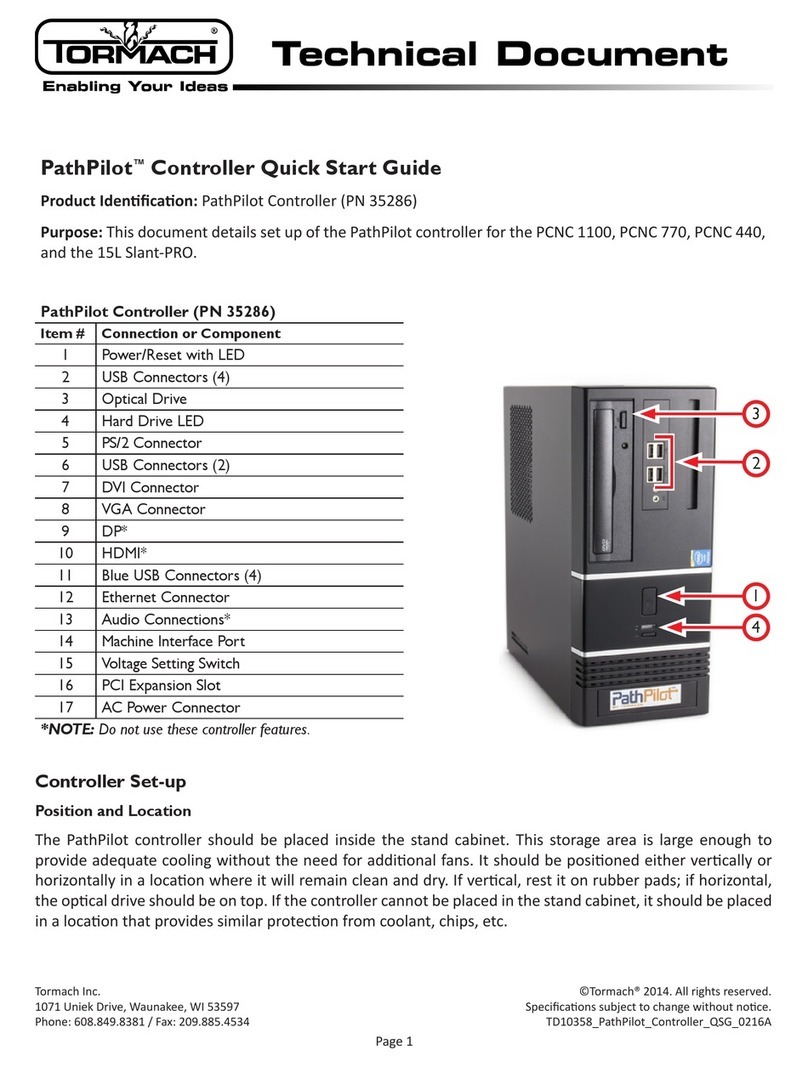
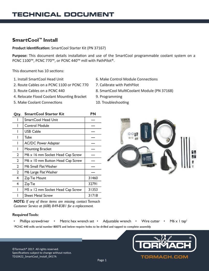
Tormach ECM1V1.5 User manual

TECHNICAL DOCUMENT Version 0420A
INSTALLATION GUIDE
ECM1V1.5 UPDATE KIT
Page 1

?
LOOKING FOR A VIDEO?
Before you begin, select the image below to watch a
walk-through video of this entire installation procedure.
1.1 PURPOSE
This document gives instructions on installing the ECM1v1.5 Update
Kit on a mill.
1.2 PRODUCT INFORMATION
Product: ECM1v1.5 Update Kit (PN39257)
Quantity Description
1 3 AFuse (PN 31120)
1 10-Pin Terminal Block (PN32632)
1 Crimp Cap (PN38453)
1 ECMv1.5 Board (PN37509)
1 ECMv1.5 Protective Cover (PN37518)
8 Nylon Standoff (PN38688)
1 Return Shipping Label
3 Wires 443-445 (PN35667)
Note: If any items are missing, we can help. Email
support@tormach.com to contact Tormach Technical
Support for guidance on how to proceed.
1.3 REQUIRED TOOLS
This procedure requires the following tools. Collect them before you
begin.
lFlat-blade screwdriver
lFlat-blade screwdriver, small
lPhillips screwdriver
lWire crimper (or similar)
Page 2
©Tormach® 2020
Specifications subject to change without notice.
tormach.com
TD10571: Installation Guide: ECMv1.5 Update Kit (0420A)
TECHNICAL DOCUMENT

2.1 REPLACE THE ECM BOARD
Complete the following steps in the order listed:
2.1.1 Remove the ECMv1.4 Board 3
2.1.2 Install the ECM v1.5 Board 4
2.1.1 Remove the ECMv1.4 Board
Note: To receive a refund/core charge payment, you must
return the ECM v1.4 board back to us in the electrostatic
safe bag provided.
WARNING! Electrical Shock Hazard: You must power off
the machine before making any electrical connections. If
you don't, there's a risk of electrocution or shock.
1. Power off the machine and the PathPilot controller.
a. Push in the Emergency Stop button on the operator box,
which removes power to motion control.
b. From the PathPilot interface, select Exit.
c. Turn the Main Disconnect switch to OFF on the side of the
electrical cabinet.
d. Remove the power plug(s) from the wall outlet. If your
system is hardwired, isolate the machine by opening its
circuit breaker(s).
e. Follow correct lockout/tagout procedures.
2. Remove the wire trough covers shown in the following image.
Figure 2-1: Wire troughs removed from the electrical
cabinet.
3. Use a Phillips screwdriver to remove the four Phillips head
screws that secure the ECM board shield to the ECM board.
Then, set aside the screws for later use, and discard the
shield.
Figure 2-2: Four Phillips head screws securing the shield to
the ECM board.
Page 3
©Tormach® 2020
Specifications subject to change without notice.
tormach.com
TD10571: Installation Guide: ECMv1.5 Update Kit (0420A)
TECHNICAL DOCUMENT

4. Identify the Accessory 1 input connector and the Accessory 2
input connector on the ECM board (both white). To correctly
reinstall them later in this procedure, put a mark on the top
connector (Accessory 1) with a marker.
NOTICE! If the accessory input connectors are put back
incorrectly, it could damage any (optional) accessory
probes.
5. Disconnect each connector from the ECM board.
6. Use your fingers to loosen and remove the four brass
standoffs that secure the ECM board to the electrical panel.
Figure 2-3: Four standoffs securing the ECM board to the
electrical cabinet.
7. Set aside the ECM v1.4 board.
8. Remove the remaining four brass standoffs from the
electrical cabinet. Then, discard all eight brass standoffs that
you removed in this procedure.
2.1.2 Install the ECM v1.5 Board
1. For the ECM v1.5 board to correctly fit in the electrical
cabinet, you must first remove two tabs from the top wire
trough: bend the tabs back-and-forth until you can remove
them from the wire trough, as shown in the following image.
Figure 2-4: Two tabs removed from the top wire trough.
2. Find the eight nylon standoffs provided.
NOTICE! To prevent damage to the ECM board from
over-tightening, use your fingers to tighten the
standoffs.
3. In place of the four brass standoffs that you removed in
"Remove the ECMv1.4 Board" (on the previous page), install
four nylon standoffs into the electrical cabinet.
4. Find the ECM v1.5, and remove it from the electrostatic safe
bag. Then, set the bag aside.
Note: To receive a refund/core charge payment, you
must return the ECM v1.4 board back to us in the
electrostatic safe bag provided.
5. Mount the ECM v1.5 board into the electrical cabinet with the
four remaining nylon standoffs. Verify that the logo on the
ECM board is upright, as shown in the following image.
Figure 2-5: ECMv1.5 board installed in the electrical
cabinet.
6. Identify the jumpers on the ECMv1.5 board, as shown in the
following image.
Figure 2-6: Jumper on the ECM v1.5 board.
Page 4
©Tormach® 2020
Specifications subject to change without notice.
tormach.com
TD10571: Installation Guide: ECMv1.5 Update Kit (0420A)
TECHNICAL DOCUMENT

7. Verify that the WS5 and WS6 jumpers are in the FROM
EEPROM position. WS5 connects pins 2 and 3; WS6 connects
pins 1 and 2.
Figure 2-7: Jumpers on the ECM v1.5 board.
Note: The position details are printed on the ECM
v1.5 board itself.
8. Make the wire connections on connector J1. From left to right,
attach the wires with a small, flat-blade screwdriver as
follows:
a. Attach wires 445 through 443.
b. Transfer wires 402 through 408 from the old connector J1
into the new connector J1.
Figure 2-8: Wires from the old connector J1 and wires
from the new connector J1.
9. When finished, verify that the wires in connector J1 are
configured as shown in the following image.
Figure 2-9: Final wire configuration for connector J1.
10. Put all connectors back on the ECM v1.5 board.
Figure 2-10: ECM v1.5 board correctly installed in the
electrical cabinet.
11. Verify that the following connections on the ECM board are
correct:
lOn connector J3, the white connector has a mark (that you
made in "Remove the ECMv1.4 Board" (page3)).
lOn connector J4, the white connector doesn't have a mark.
12. Find the fuse provided.
13. Install the fuse in F1, as shown in the following image.
Figure 2-11: F1 on the ECM v1.5 board.
14. Find the ECM v1.5 protective cover provided.
Page 5
©Tormach® 2020
Specifications subject to change without notice.
tormach.com
TD10571: Installation Guide: ECMv1.5 Update Kit (0420A)
TECHNICAL DOCUMENT

15. Attach the protective cover with a Phillips screwdriver, using
the four Phillips head screws that you set aside in "Remove
the ECMv1.4 Board" (page3).
16. Put the ECM v1.4 board into the electrostatic safe bag that
you set aside earlier. Then, package the ECM v1.4 board for
shipping.
Page 6
©Tormach® 2020
Specifications subject to change without notice.
tormach.com
TD10571: Installation Guide: ECMv1.5 Update Kit (0420A)
TECHNICAL DOCUMENT

2.2 MAKE VFD CONNECTIONS
1. Turn the latch on the VFD cover with a flat-blade screwdriver.
Then, slide down and remove the cover, and set it aside.
Figure 2-12: Removing the cover from the VFD.
2. Identify wire 403 in terminal T41 and terminal T1. Verify that
there are two wires in terminal T1, as shown in the following
image.
Figure 2-13: Wire 403 on the VFD.
3. Depending on the wire orientation identified in Step 2, do one
of the following:
lTwo Wires in T1 Go to Step 4.
lTwo Wires in T41 Remove wire 403 from terminal T41
and T1, and install the two-wire end of 403 in terminal T1.
Then, go to Step 5.
4. Remove the one-wire end of 403 from terminal T41.
5. Find the ferrule cap provided.
6. Secure the ferrule cap onto the one-wire end of wire 403 with
a wire crimper.
Figure 2-14: Ferrule cap on wire 403.
7. Use a small, flat-blade screwdriver to connect the following
wires from connector J1 to the VFD:
Wire VFD Connector
443 T5
444 T13
445 T41
8. Replace the VFD cover that you set aside inStep 1.
9. Put all wires into the wire troughs, and then replace the wire
trough covers that you removed in "Remove the ECMv1.4
Board" (page3).
10. Close the electrical cabinet door.
Page 7
©Tormach® 2020
Specifications subject to change without notice.
tormach.com
TD10571: Installation Guide: ECMv1.5 Update Kit (0420A)
TECHNICAL DOCUMENT

3.1 VERIFY THE INSTALLATION
1. Power on the machine and the PathPilot controller.
a. Insert the power plug(s) into the wall outlet. If your system
is hardwired, restore power to the circuit breaker(s).
b. Turn the Main Disconnect switch to ONon the side of the
electrical cabinet.
c. Twist out the Emergency Stop button on the operator box,
which enables movement to the machine axes and the
spindle.
d. Press the Reset button on the operator box.
2. Do a test of the axes movement:jog the machine in each
direction, and confirm that they move as expected.
3. Do a test of the spindle movement:move the spindle in each
direction, and confirm that it moves as expected.
4. Depending on the results of Steps 2 through 3, do one of the
following:
lCorrect Movement You've completed the installation of
the ECM Upgrade Kit.
lIncorrect Movement We can help. Email
support@tormach.com to contact Tormach Technical
Support for guidance on how to proceed.
Page 8
©Tormach® 2020
Specifications subject to change without notice.
tormach.com
TD10571: Installation Guide: ECMv1.5 Update Kit (0420A)
TECHNICAL DOCUMENT
This manual suits for next models
1
Table of contents
Other Tormach Controllers manuals
Popular Controllers manuals by other brands
National Instruments
National Instruments PXI-8150B Note to Users
IFM Electronic
IFM Electronic CR0451 System manual

Moxa Technologies
Moxa Technologies ioThinx 4530 Series Quick installation guide

MICRO-AIR
MICRO-AIR EasyTouch Operation manual
Reely
Reely LiPo Checker operating instructions

Siemens
Siemens LME7 Series manual
