Vital Systems pn7737 User manual


7737 User Guide
© 2021 Vital Systems, Inc. 1 www.vitalsystem.com
Contents
INTRODUCTION ....................................................................................................................................... 3
VSI DEVICE MANAGER SETUP................................................................................................................... 4
PRE-REQUISITES TO GET MOTION WORKING ON 7737 WITH:.................................................................. 5
HiCON Integra............................................................................................................................................. 5
DSPMCv3 .................................................................................................................................................... 5
HICON INTEGRA CONNECTION DIAGRAMS WITH BLACK 7866 ................................................................. 6
Connection to J7 ......................................................................................................................................... 6
Connection to J8 ......................................................................................................................................... 7
HICON INTEGRA CONNECTION DIAGRAMS WITH BLUE 7766 ................................................................... 8
Connection to J8 ......................................................................................................................................... 8
Connection to J7 ......................................................................................................................................... 9
CONNECTION DIAGRAM WITH DSPMC .................................................................................................. 10
PIN LAYOUT ON RJ45 PORTS.................................................................................................................. 11
RJ45 TO SERVO/STEPPER DRIVE CONNECTIONS..................................................................................... 12

7737 User Guide
© 2021 Vital Systems, Inc. 2 www.vitalsystem.com
License Agreement
Before using the 7737 and accompanying software tools, please take a moment to go thru this License
agreement. Any use of this hardware and software indicate your acceptance to this agreement.
It is the nature of all machine tools that they are dangerous devices. In order to be permitted to use
7737 on any machine you must agree to the following license:
I agree that no-one other than the owner of this machine, will, under any circumstances be responsible,
for the operation, safety, and use of this machine. I agree there is no situation under which I would
consider Vital Systems, or any of its distributors to be responsible for any losses, damages, or other
misfortunes suffered through the use of the 7737 board and its software. I understand that the 7737
board is very complex, and though the engineers make every effort to achieve a bug free environment,
that I will hold no-one other than myself responsible for mistakes, errors, material loss, personal
damages, secondary damages, faults or errors of any kind, caused by any circumstance, any bugs, or any
undesired response by the board and its software while running my machine or device.
I fully accept all responsibility for the operation of this machine while under the control of 7737, and for
its operation by others who may use the machine. It is my responsibility to warn any others who may
operate any device under the control of 7737 board of the limitations so imposed.
I fully accept the above statements, and I will comply at all times with standard operating procedures
and safety requirements pertinent to my area or country, and will endeavor to ensure the safety of all
operators, as well as anyone near or in the area of my machine.
WARNING: Machines in motion can be extremely
dangerous! It is the responsibility of the user to design
effective error handling and safety protection as part of
the system. VITAL Systems shall not be liable or
responsible for any incidental or consequential damages.
By using this product, you agree to the license agreement.

7737 User Guide
© 2021 Vital Systems, Inc. 3 www.vitalsystem.com
Introduction
The pn7737 Differential Step/Direction and Encoder Board allows access to the Step/Direction channels
and more Encoder channels for the HiCON Integra (pn7766) or DSPMC (pnn7762) .
When used in tandem with a Drive Interface Board (EPx-DIB) for Maxsine AC Servo Drives, the 7737 allows
a simple plug-and-play setup using HiCON Integra and DSPMC motion controllers.
Features:
•Color-coded RJ45 plugs for Controller-to-Drive Step/Dir and Encoder cables.
•4 Differential Encoder Channels
•4 Step/Dir Output Channels
•Drive Enable and 1 General Purpose 24V NPN Outputs
•Hardware Estop and Drive Error Inputs
•Status LEDs for I/O signals.
IMPORTANT: PLEASE READ!!
pn7737 Estop Notes:
•Estop signal can be overridden by installing a jumper between Estop and adjacent
24V terminals
•Drive Enable signal is automatically disabled if Estop is triggered
•Combined Estop on HiCON Integra (between J7 and J8) signal on Port14, input15 is
preferred for Mach Estop pin mapping
•Use straight-thru RJ45 patch cables when connecting the 7737 breakout board to
the Maxsine EPx-DIB drive interface board.

7737 User Guide
© 2021 Vital Systems, Inc. 4 www.vitalsystem.com
VSI Device Manager Setup
The Integra J8 and J7 as well as DSPMC J11 and J12 expansion headers must be enabled for 7737
step/dir before use. To do this, open the VSI Device Manager and scan the network for your device.
Once the device is found and selected, open the HiCON or DSPMC tab, highlight the desired expansion
port and mark the value for the Enabled option. Press the Download button to send the changes to the
device. If you are only using one 7737 board, make sure to only enable one expansion header. If you
enable both headers and only one 7737 board is plugged, it will be permanently stuck in estop
condition.

7737 User Guide
© 2021 Vital Systems, Inc. 5 www.vitalsystem.com
Pre-requisites to get motion working on 7737 with:
HiCON Integra
The 7737 and Integra combo requires these steps for proper operation:
1. Make sure that Integra has an Extended I/O Activation.
2. Enable J7/J8 plugs for Step/Dir operation using VSI Device Manager.
3. Map the Drive Enable pin of 7737 on Mach4. Make sure the polarity is such that when Mach4 is
enabled, blue LED lights up on the 7737 Board.
4. Make sure ESTOP jumper is installed or ESTOP switch is closed on the 7737.
5. Optionally map Drive Error Signal.
DSPMCv3
The 7737 and DSPMC require these steps for proper operation:
1. Enable J5/J6 plugs for use with the 7737 in the HiCON tab of the VSI Device Manager.
2. Map the Drive Enable pin of 7737 on Mach4. Make sure the polarity is such that when Mach4 is
enabled, blue LED lights up on the 7737 Board.
3. Make sure ESTOP jumper is installed or ESTOP switch is closed on the 7737.
4. Optionally map Drive Error Signal.

7737 User Guide
© 2021 Vital Systems, Inc. 6 www.vitalsystem.com
HiCON Integra Connection Diagrams with Black 7866
Connection to J7
GND
+24V
7737 Differential
Step/Dir and
Encoder Board
J4
Drive Interface
Board (EPx-DIB)
ENC
DRV
J4
Drive Interface
Board (EPx-DIB)
ENC
DRV
AC Servo Drive
AC Servo Drive
24V power
source from
HiCON Integra J16
(Short Cable Length)
J3
SG1
J2
J1
Setup Diagram for 7737 Board and HiCON Integra 7866 (J7)
EStop
GPO-A
General Purpose Output
(NPN, Sinking 24V 2A)
Port13 Out6 >> GPO-A
Drive Enable
26-pin
Flat cable
Connected to J7
Drive Enable Signals
for additional motors
not using 7737 Board
SG2
SG3
ENC3
ENC4
ENC5
ENC6
SG0
J4
Drive Interface
Board (EPx-DIB)
ENC
DRV
AC Servo Drive
J4
Drive Interface
Board (EPx-DIB)
ENC
DRV
AC Servo Drive
J9 J1
Motor 1
Motor 0
Motor 2
Motor 3
Mach pin mapping (J7):
•Drive Enable –Port12, Out4
•GPO-A –Port12, Out6
•Estop –Port12, In12
External Power:
+24V and GND should be sourced from the
J16 header on the Integra and the wires
should be as short as possible.

7737 User Guide
© 2021 Vital Systems, Inc. 7 www.vitalsystem.com
Connection to J8
GND
+24V
7737 Differential
Step/Dir and
Encoder Board
J4
Drive Interface
Board (EPx-DIB)
ENC
DRV
J4
Drive Interface
Board (EPx-DIB)
ENC
DRV
AC Servo Drive
AC Servo Drive
24V power from
HiCON Integra J16
(Short Cable Length)
J3
SG5
J2
J1
Setup Diagram for 7737 Board and HiCON Integra 7866 (J8)
EStop
GPO-A
General Purpose
Output (NPN, Sinking
24V 2A)
Port12 Out6 >> GPO-A
Drive Enable
Drive Enable Signals
for additional motors
not using 7737 Board
ENC7
ENC8
SG4
26-pin
Flat cable
Connected to J8
J9 J1
Motor 4
Motor 5
Mach pin mapping (J8):
•Drive Enable –Port13, Out4
•GPO-A –Port13, Out6
•Estop –Port13, In12
24V Power:
+24V and GND should be sourced from the
J16 header on the Integra and the wires
should be as short as possible

7737 User Guide
© 2021 Vital Systems, Inc. 8 www.vitalsystem.com
HiCON Integra Connection Diagrams with Blue 7766
Connection to J8
GND
+24V
7737 Differential
Step/Dir and
Encoder Board
J4
Drive Interface
Board (EPx-DIB)
ENC
DRV
J4
Drive Interface
Board (EPx-DIB)
ENC
DRV
AC Servo Drive
AC Servo Drive
External power
source from
HiCON Integra J1
J3
SG1
J2
J1
Setup Diagram for 7737 Board and HiCON Integra (J8)
EStop
GPO-A
General Purpose Output
(NPN, Sinking 24V 2A)
Port13 Out6 >> GPO-A
Drive Enable
26-pin
Flat cable
Connected to J8
Drive Enable (24V,
NPN) Signal for
additional motors
SG2
SG3
ENC3
ENC4
ENC5
ENC6
SG0
J4
Drive Interface
Board (EPx-DIB)
ENC
DRV
AC Servo Drive
J4
Drive Interface
Board (EPx-DIB)
ENC
DRV
AC Servo Drive
D1
D2
D3
D4
J4
Drive error override
jumpers. (ver 2 only)
Mach pin mapping (J8):
•Drive Enable –Port13, Out4
•GPO-A –Port13, Out6
•Estop –Port13, In12 (44 for VSIDeviceManager
Estop setting)
24V Power:
+24V and GND should be sourced from the
J16 header on the Integra and the wires
should be as short as possible.
24V power from
HiCON Integra
J16 (Short Cable)

7737 User Guide
© 2021 Vital Systems, Inc. 9 www.vitalsystem.com
Connection to J7
GND
+24V
7737 Differential
Step/Dir and
Encoder Board
J4
Drive Interface
Board (EPx-DIB)
ENC
DRV
J4
Drive Interface
Board (EPx-DIB)
ENC
DRV
AC Servo Drive
AC Servo Drive
External power
source from
HiCON Integra J1
J3
SG5
J2
J1
Setup Diagram for 7737 Board and HiCON Integra (J7)
EStop
GPO-A
General Purpose Output
(NPN, Sinking 24V 2A)
Port12 Out6 >> GPO-A
Drive Enable
26-pin
Flat cable
Connected to J7
Drive Enable (24V,
NPN) Signal for
additional motors
ENC7
ENC8
SG4D1
D2
D3
D4
J4
Drive error override
jumpers. (ver 2 only)
Mach pin mapping (J7):
•Drive Enable –Port12, Out4
•GPO-A –Port12, Out6
•Estop –Port12, In12 (38 for VSIDeviceManager
Estop setting)
External Power:
+24V and GND should be sourced from
the J16 header on the Integra and the
wires should be as short as possible.
24V power from
HiCON Integra
J16 (Short Cable)

7737 User Guide
© 2021 Vital Systems, Inc. 10 www.vitalsystem.com
Connection Diagram with DSPMC

7737 User Guide
© 2021 Vital Systems, Inc. 11 www.vitalsystem.com
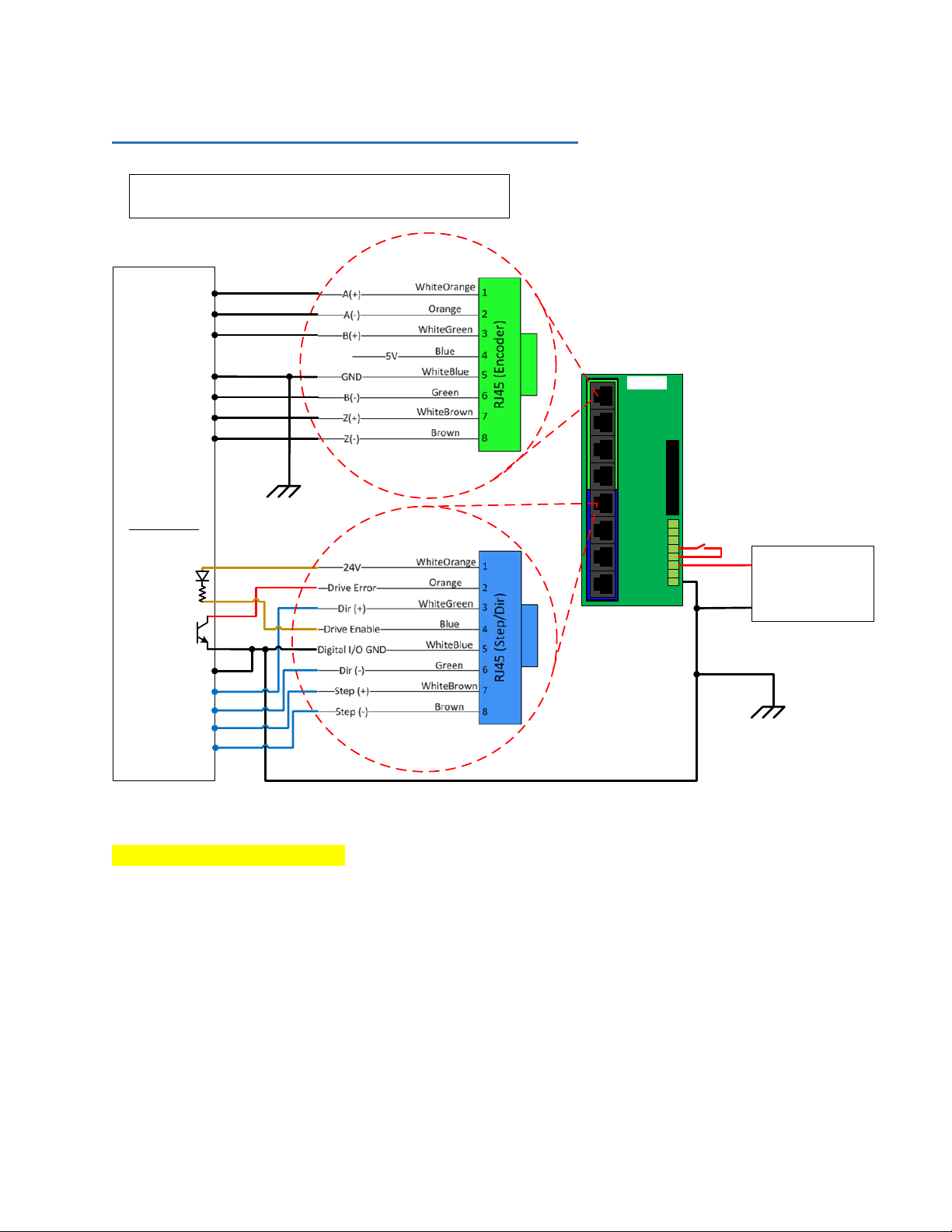
Pin Layout on RJ45 Ports
Use straight-thru RJ45 patch cables when connecting the 7737 breakout board to the Maxsine EPx-DIB
drive interface board.
Wiring Diagram for RJ45 Ports (Encoder and Step/Dir Channels)
on 7737 Board
Blue RJ45
Green RJ45
7737
Drive Error and Drive Enable signals are NPN (active Low)
The drawing below shows the connection between the servo drive and the 7737 board:
7737 User Guide
© 2021 Vital Systems, Inc. 12 www.vitalsystem.com
RJ45 to Servo/Stepper Drive Connections
Servo Drive
Alarm
J3
SG1
J2
J1
SG2
SG3
ENC3
ENC4
ENC5
ENC6
SG0
Servo ON
0V
GND
+24V
+24V
ESTOP
GPO_A
ENABLE
ERROR
7737
POWER
SUPPLIED FROM J16
on HiCON INTEGRA
(-)
(+)
Earth
Ground
(VERY IMPORTANT!!)
ENC Out (A+)
ENC Out (A-)
ENC Out (B+)
ENC Out (B-)
ENC Out (Z+)
ENC Out (Z-)
Servo Drive Wiring Diagram
GND 0V
ENC Out (B-)
Dir In+
Dir In-
Step In+
Step In-
Note About Servo Alarm Output: For normal operation, the alarm output from the drive should be ON
(active). When the Alarm output is OFF (open circuit) the 7737 reads it as a fault condition. You can
override the fault condition by installing the jumper on J4 Drive Error override. We recommend you
install the jumpers for all unused Drive-Error signals.
Table of contents
Other Vital Systems Media Converter manuals


