1 9
1 8
5.2. WORK
Where the unit automatically
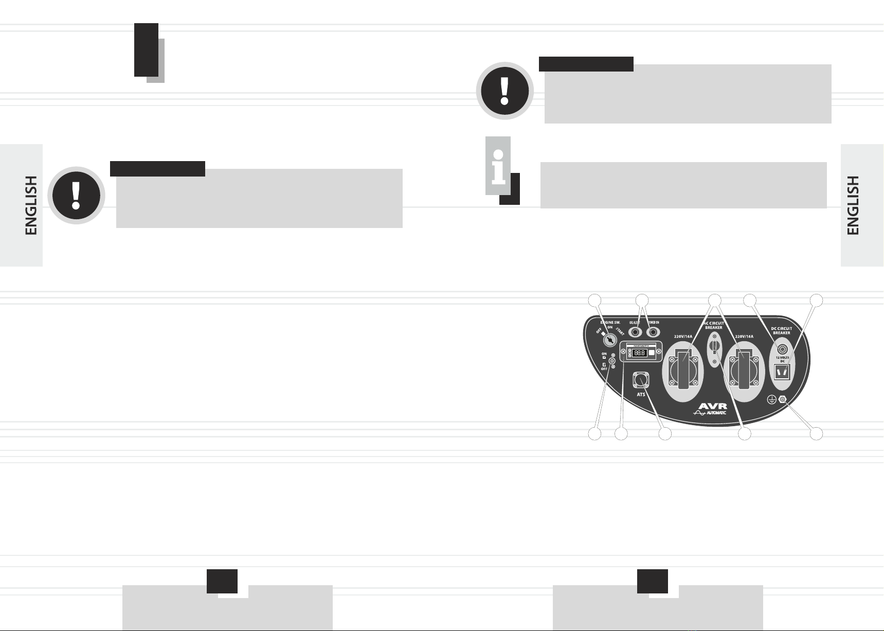
1. Insert the ignition key into the ignition switch (1) mini electrical power
stations EST5.8ba (see Fig. 1) and turn it to «ON».
2. On the automation unit (see Fig. 2) press (1) «ON / OFF» (Position
«ON»). Automation unit will check your system and go into operational
readiness. The power plant will go into standby mode automatic start in the
absence of stresses in the supply or change in the minimum threshold
(Maximum). Voltage monitoring relay with will monitor value of the input
voltage of the external power supply.
3. If the voltage of the external power supply will be gone completely or
(Using a voltage monitoring relay) go beyond minimum or maximum
threshold, the electronic unit automation will give instantaneous power control
signal to starting. If the engine does not start in the power for 3-10 seconds, the
unit will give automatic power control signal to restart the engine.
4. When the engine speed reaches 2,500 r / min or more, automation unit
connects to the power supply voltage of the consumer (Load), that is, the
voltage to the consumer will go after 2-5 seconds after the engine plant. If the
speed is Engine power will be less than 2500 r / min, the block automation will
be in standby mode.
If, after several attempts to start the engine power is not start, automation
unit will give power manager signal «Stop». In this case, the block automatic
press «ON / OFF» (position «OFF»), find out the cause of the problem,
referring to the section 8, "Troubleshooting and ways to elimination Manuals
mini electrical power stations EST5.8ba.
After a fault, press the «ON / OFF» (position «ON»). If after repeated
attempts, the engine does not started, contact the service center.
5. As soon as the power supply in the external power supply resume or
voltage returns within the minimum threshold or maximum (only when using
voltage control relays) electronic automatic unit after 4 seconds will give
power control signal to the motor to stop. Engine power to stop for 5-10
seconds after control signal.
ATTENTION!
Connecting the power cables should perform a qualified
electrician.
WARNING!
When the engine is running battery power should be in the
circuit. If you disconnect the battery or cable automation
engine is running, automation unit off.
WARNING!
In the automatic start button manually start / stop the engine
power «Start / Stop» not functioning.