Vitek Transcendent VTC-THB2RMS User manual

VITEK
VTC-THB2RMS
VTC-THT2RMS
VTD-THD2RMS
Transcendent 2.0 Megapixel Indoor/Outdoor
4-IN-1 Starlight Motorized Lens Cameras
• 1/2.8” 2.0 MegaPixel Progressive Scan CMOS
Sensor
• Advanced Starlight Technology Offers Dramatically
Higher Sensitivity to Light Producing Color Images in
Very Dark & Night Scenes
• High Definition Analog (HDA): HD-TVI / AHD / CVI
/ CVBS (Selectable) Video Output
• 2.8-12mm Motorized Varifocal Lens
• Matrix IRs with up to 165’ Range (VTC-THB2RMS),
Matrix IRs with up to 165’ Range (VTC-THT2RMS),
Matrix IRs with up to 100’ Range (VTD-THD2RMS)
• True Wide Dynamic Range (WDR)
• True Mechanical Day/Night function by ICR
• 3D-DNR Noise Reduction
• IP67 Weather Resistance
IK10 (VTD-THD2RMS Only)
• Supports Up The COAX Control
• Over 1500’ HD Video Transmission (Depending on
cable characteristics and integrity)
• Optional Mounts Available (see rear page)
• 12VDC Operation
• 3 Year Warranty
FEATURES
PLEASE NOTE:
Complete User Guide, Software, Tools,
and Updates are available online. Scan
the QR Code or visit:
http://www.vitekcctv.com/Downloads
* VTC-THT2RMS also available in
charcoal (VTC-THT2RMSB)

2
Safety Precaution
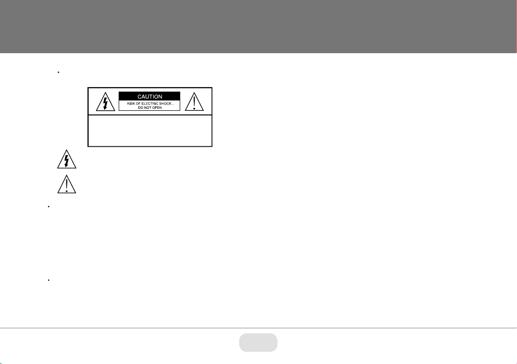
CAUTION: TO REDUCE THE RISK OF ELECTICAL
SHOCK, DO NOT REMOVE COVER (OR BACK).
NO USER SERVICEABLE PARTS INSIDE.
REFER SERVICING TO QUALIFIED SERVICE PERSONNEL
To prevent electrical shock and risk of fire hazards, do not expose this unit
to rain or moisture and only use specified power source..
Warning :
This equipment has been tested and found tocomply with the limits for a Class
A digital device, pursuant to part 15 of the FCC Rules. These limits are designed
to provide reasonable protection against harmful interference when the equipment
is operated in a commercial environment. This equipment generates, uses, and
can radiate radio frequency energy and, if not installed and used in accordance with
the instruction manual, may cause harmful interference to radio communications.
Operation of this equipment in a residential area is likely tocause harmful
interference in which case the user will be required tocorrect the interference at
their own expense.
Caution :
Any changes or modifications in construction of this device which are not expressly
approved by the party responsible for compliance could void the user's authority
to operate the equipment.
Main power quality should be that of atypical commercial environment. If the user
of the model requires continued operation during power interruptions, it is
recommended that the device be powered from an uninterruptible power supply
(UPS).
The symbol is intended to alert the user to the presence of important
operating and maintenance (servicing) instructions in the literature
accompanying the unit.
The symbol is intended to alert the user tothe presence of uninsulated
"dangerous voltage" within the product's enclosure that may be of
sufficient magnitude toconstitute a risk of electrical shock.
Limited Product Warranty
VITEK products carry a three (3) year limited warranty. VITEK warrants to
the purchaser that products manufactured by VITEK are free of any rightful
claim of infringement or the like, and when used in the manner intended,
will be free of defects in materials and workmanship for a period of three
(3) years, or as otherwise stated above, from the date of purchase by the
end user. This warranty is nontransferable and extends only to the original
buyer or end user customer of a VITEK Authorized Reseller.
The product must have been used only for its intended purpose, and not
been subjected to damage by misuse, willful or accidental damage, caused
by excessive voltage or lightning.
The product must not have been tampered with in any way or the
guarantee will be considered null and void.
This guarantee does not affect your statutory rights.
Contact your local VITEK Reseller should servicing become necessary.
VITEK makes no warranty or guarantee whatsoever with respect to
products sold or purchased through unauthorized sales channels. Warranty
support is available only if product is purchased through a VITEK
Authorized Reseller.

3
VTC-THB2RMS - Components
Overview
34
57
6
Lens
Sun Shield
Mount Lock
Mount Base
BNC Video Output
Output Mode Switch
Power Cable
1
2
3
4
5
6
7
2
1
Video Connection
Connect the BNC video connector to a BNC cable, then to a DVR.
Power
12VDC
Power Connection
Connect the power connector to a regulated 12 VDC power adaptor.
Monitor
Video
Camera
Manual
Drill Template
Screws
Allen Key
This series supports TVI/AHD/CVI/CVBS video output. Before switching
video outputs, please remove the cover of the video switch cable. The video
output can be changed by pressing and holding the button in the video
switch cable for 5 seconds (TVI is the default video output).
Video Output Mode Switch:
Video Switch Cable

4
Installation
Before beginning installation, make
sure that the wall or ceiling is strong
enough to withstand 3 times the weight
of the camera. The mounting steps are:
2. Route the cables and connect the power & video cables, use the
rubber plug to fill the gap of the mounting base, then secure the
mounting base to the ceiling or wall with screws.
Rubber plug
3. Loosen the mount lock to adjust the pan and tilt, then tighten the
mount lock to secure the viewing angle adjustments.
4. Carefully remove the protective film from the lens to complete the
installation.
90° T ILT
360° ROTATION
360° PAN
FIXED RING
1. Attach the drill template to
the place where you want to
install the camera, then drill
4 screw holes and 1 cable
hole (if routing the cables
through the mounting base)
according to the drill
template

5
VTC-THT2RMS Components
Overview
2
1
3
4
Camera
Manual
Screws
Allen Key
Mounting Plate
Rubber Plug
Lens
Lock Screws
BNC Video Output
Output Mode Switch
Power Cable
1
2
3
4
5
5
Monitor
Video
Video Connection
Connect the BNC video connector to a BNC cable, then to a DVR.
Power Connection
Connect the power connector to a regulated 12 VDC power adaptor.
Power
12VDC
This series supports TVI/AHD/CVI/CVBS video output. Before switching
video outputs, please remove the cover of the video switch cable. The video
output can be changed by pressing and holding the button in the video
switch cable for 5 seconds (TVI is the default video output).
Video Output Mode Switch:
Video Switch Cable

6
Installation
Before you begin, please make sure that the wall or ceiling is strong
enough to withstand 3 times the weight of the camera. The mounting
steps are as follows:
1. Attach the drill template to
the place where you want to
install the camera, then drill
3 screw holes and 1 cable
hole (if you want to route the
cables through the mounting
base) according to the drill
template
.
2. Route the cables and
connect the power & video
cables, then secure the
mounting base to the ceiling
or wall with screws.
3. Loosen the lock screws, then
adjust the camera to obtain
the optimium viewing angle.
Confirm the correct viewing
angle with a monitor. Next
insert the rubber plug.
4. Tighten the lock screws to secure the viewing angle adjustments.
Rubber Plug

7
VTD-THD2RMS Components
Overview
Camera
Manual
Drill Template
Screws
Allen Key
Mounting Base
Dome Cover Output Mode Switch
Power Cable
1
2
3
4
5
1
2
3
4
5
Monitor
Video
Video Connection
Connect the BNC video connector to a BNC cable, then to a DVR.
Power Connection
Connect the power connector to a regulated 12 VDC power adaptor.
Power
12VDC
BNC Video Output
6
Trim Ring
6
This series supports TVI/AHD/CVI/CVBS video output. Before switching video
outputs, please remove the cover of the video switch cable.
The video output can be changed by pressing and holding the button in
the video switch cable for 5 seconds (TVI is the default video output).
Video Output Mode Switch:
Video Switch Cable

8
Installation
Before beginning installation, make sure that the wall or ceiling is
strong enough to withstand 3 times the weight of the camera. The
mounting steps are as follows:
Loosen the screws to open
the lower dome and then
loosen the lock screw to
remove the mounting base.
1. Attach the drill template to
the place where you want to
install the camera, then drill
the screw holes and 1 cable
hole according to the drill
template.
3. Route the cables and
connect the power & video
cables, use the rubber plug
to fill the gap of the mounting
base. then secure the
mounting base to the ceiling
or wall with screws.
4. Adjust the Three-axis camera bracket to obtain the optimium
viewing angle.
5. Install the dome bubble on
the camera with the screws,
then replace the trim ring
by turning it clockwise.
Finally, carefully remove the
protective film to complete the
installation.
Pan: 0°~240°
Rotation: 0°~220° Tilt: 0°~68°
2. *Unscrew the trim ring by turning it
counter-clockwise. This will enable
removal of the lower dome.

9
1. Click once on the image you want to adjust and then click on the PTZ icon on the sub toolbar
2. The PTZ screen will open and using the Zoom -/+ the lens in the camera will now Zoom in or out
and will auto focus
Adjusting the Motorized Lens

10
Camera OSD Menu
The Transcendent 4-in1 camera series must be connected to a DVR
which supports HD-TVI/AHD video signal input and COC protocol to
access the OSD setup menu. Different DVRs manufacturers may have
different modes of menu operation.
You can select the menu by clicking (U) or (D) key on the
direction area. Click (L) or (R) key to select the menu on the
left. The menu with arrow icon which means it has sub-menu. You
can select the menu and click the Enter Button to enter the
sub-menu. to return to previous screen, arrow down to Return and
click Enter Button. To Exit menu arrow down to Exit and click Enter
Button.
You will see the following interface by clicking the PTZ button.
The Following image will pop-up when you left click once on the
image when using Transcendent HDA DVR's.
Click on the OSD tab and then click on the camera menu
button.

11
Detailed Specifications VTC-THB2RMS VTC-THT2RMS / VTC-THT2RMSB VTD-THD2RMS
Image Sensor
Signal System
Effective Pixels
Resolution
Video Output
Lens
Day/Night
Min. IIIumination
IR LEDs
IR Distance
S/N Ratio
WDR
Other Features
Digital Noise Reduction (DNR)
White Balance
BLC, LSC, HLC
Control over COAX (COC)
Transmission Distance
Power Input
Power Consumption (12VDC)
Ingress / Impact Resistance
Operation Conditions
Weight
Dimensions
1/2.8” 2 Megapixel Progressive Scan CMOS Sensor with Advanced Starlight Technology
NTSC/PAL
1920 x 1080
HD-TVI / AHD / CVI: 2 MegaPixel / CVBS: 960H
HD-TVI / AHD / CVI / CVBS (Selectable)
2.8-12mm Motorized Varifocal
True Day/Night by ICR
2 Matrix IRs
165’
52dB (AGC Off)
True WDR (120Db)
Auto Gain Control, Auto White Balance, Freeze, Mirror, Sharpness, Smart IR, Motion Detction, Privacy Mask, Auto Defect Correction
3D-DNR
Auto (AWB)
Backlight Compensation, Lens Shading Compensation, Highlight Compensation (YES)
YES
Up to 1500’ (Depending on cable characteristics & integrity)
12VDC
IP67
-4~122 / 10%~90% Humidity
165’
IP67
21.16 oz. / 1.32 lbs. / 600g
8.68 x 3.15 x 2.78” (220.5 x 80.1 x 70.5mm)
100’
IP67 + IK10
5.56” x 3.94” (141 x 100mm) Dia x H
22.58 0z / 1.41 lbs. / 640g
5.13 x 4.23” (130 x 110mm) Dia x W
28.92oz / 1.81lbs. / 820g
2 Matrix IRs 3 Matrix IRs
IR Off: 125mA / IR ON: 700mAIR Off: 125mA / IR On: 700mA IR Off: 125mA / IR On: 420mA

OPTIONAL MOUNTS FOR TRANSCENDENT
STARLIGHT MOTORIZED VARIFOCAL CAMERAS
28492 CONSTELLATION ROAD, VALENCIA, CA 91355 WWW.VITEKCCTV.COM
Version 2.0
OCT. 2020
VT-TJB010
Optional Junction
Box for Use with
Select
Transcendent
Motorized Domes
VT-TWM03
Optional Wall
Mount for use
with Select
Transcendent
Motorized
Turrets
VT-TJB021
Optional Junction
Box for use with
Select
Transcendent
Motorized Turrets
VT-TJB01
Optional Junction
Box for use with
Select
Transcendent
Cameras
VT-TWMT-4
Optional Wall
Mount for use
with Select
Transcendent
Motorized Turrets
VT-TR4VPK
Video and Power Balun
Transmitter / Receiver
Pair for HD-TVI / AHD
/ CVI for Distances Up
to 1000’
VT-TR4K
Passive Video Balun
Transmitter / Receiver
Pair for HD-TVI / AHD
/ CVI for Distances Up
to 1440’
VT-TWMT-A2
Optional Wall
Mount for use
with Select
Transcendent
Motorized
Domes(requires
VT-TJB010)
VT-TPDM-3
Pendant Mount
Post Adapter for
Select Transcen-
dent Motorized
Turrets (requires
VT-TJB021)
VT-TPDM-2
Pendant Mount
Post Adapter for
Select Transcen-
dent Motorized
Turrets (requires
VT-TJB01)
VT-TFMT-L2
Semi Flush
Ceiling Dome
Mount for
Use with Select
Transcendent
Motorized Domes
VT-TCNMT
Transcendent
Universal Corner
Adapter (requires
VT-TJB08 (for
VTC-THB2RMS),
VT-TJB08 +
VT-TWMT-A1
(for VTC-THT2RMS,
or) VT-TWMT-A2 +
VT-TJB010
(for VTD-THD2RMS)
VT-TPLMT
Transcendent
Universal Pole
Adapter (requires
VT-TJB08 (for
VTC-THB2RMS),
VT-TJB08 +
VT-TWMT-A1
(for VTC-THT2RMS),
or VT-TWMT-A2 +
VT-TJB010
(for VTD-THD2RMS)
VT-TPDMT-A2
Pendant Mount
Post Adapter for
Select Transcen-
dent Motorized
Domes (requires
VT-TJB010)
Pair with VITEK Transcendent
Series 5-in-1 Digital Video Recorders
Supporting HD-TVI / AHD / CVI / IP /
960H Cameras!
This manual suits for next models
2
Table of contents
Other Vitek Digital Camera manuals

Vitek
Vitek VTD-TND6FP User manual

Vitek
Vitek Transcendent VTC-SMKC4 User manual

Vitek
Vitek Transcendent VTC-TNB16X4MS User manual

Vitek
Vitek VTC-TNT5WFC-2 User manual

Vitek
Vitek VTC-TNT8RFA4-2 User manual

Vitek
Vitek VT-TPTZ18HR-4N User manual

Vitek
Vitek VT-TSP8 User manual

Vitek
Vitek VTC-THB8RM User manual

Vitek
Vitek VT-PIRC2/H User manual

Vitek
Vitek VT-TPTZ32HRAN-8PNS User manual