8 9
*Please research local, state and federal laws regarding the implementation of audio
surveillance.
Image Sensor
Image Size
Electronic Shutter
Min. Illumination
Lens
Day/Night
IR LEDs / IR Type
IR Distance
Video Compression
Audio Compression
Resolution
DNR
Quality
Image Setting
Analytics
Smart Alarm
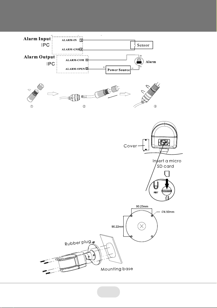
Alarm In / Alarm Out
ROI
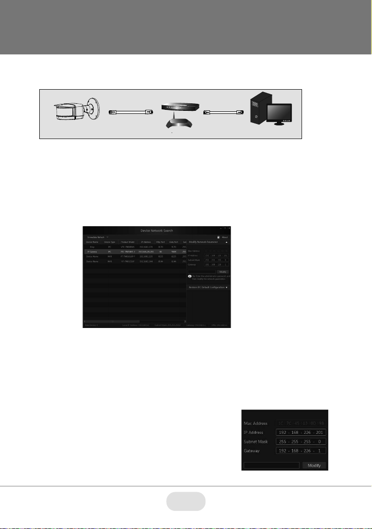
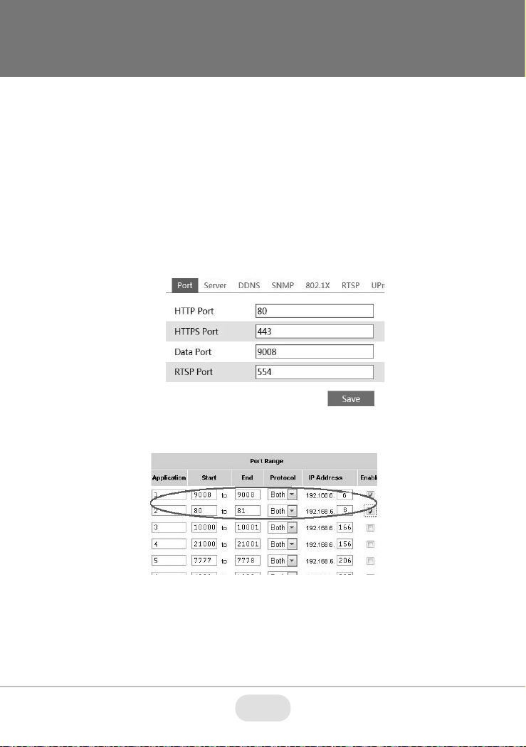
Network
Security Measures
Network Protocols
Audio
Storage Card Slot
Remote Viewing
RS 485
Supported Browsers
Connection Protocol
Weather / Impact Resistance Rating
Power
Working Environment
Dimensions / Weight
4 × 1/1.8” 4.0 Megapixel Progressive Scan CMOS
16 MegaPixel - 5520x2400
1s -1 / 10,000s (Auto / Manual)
Color: 0.008Lux @ (F2.0 AGC ON) B/W: 0.001Lux @(F2.0 AGC ON), 0 Lux with IR
4.5mm Fixed Iris Lens × 4
True Day / Night by ICR
8 / Smart IRs
80’ w/ 180 Degree Array
H.265 / H.264 / MJPEG
G.711A / G.711U
5520 × 2400, 3840 × 1680, 2784 × 1200 (30/25fps)
XD-DNR (2D-DNR & 3D-DNR)
VBR (Five Levels of Adjustment) / CBR (Adjustable)
Flip, Mirror, Saturation, Brightness, Contrast, Sharpness, AGC, and AWB adjusted by client software/browser
Line Crossing, Region Entrance / Exit
SD Card Record, Triggering Record, Notify Control Center, Uploading SD Card, Sending e-mail
1 / 1
Each ROI to be Configured Separately
RJ45 10M / 100M Ethernet Port, PoE (802.3af)
User Authentication, Host Authentication (MAC address); HTTPs encryption; IEEE802.1x Port-based Network Access Control; IP Address Filtering
HTTP, HTTPs, IPv4/IPv6, 802.1x, QoS, FTP, SMTP, UPnP, SNMP, DNS, DONS, NTP, RTSP, RTCP, RTP, TCP/IP, UDP, IGMP, ICMP, PPPoE, DHCP
1 x IN & 1 x OUT (Two-Way Audio)
Supports One MicroSD up to 256GB
CMS / Web Browser / Mobile (iOS / Android)
1 CH; Pelco-D/P Protocol, Custom Protocols Available
Internet Explorer 8-11, Edge in IE Mode
ONVIF, API, SDK
IP67 / IK10
12VDC / PoE (802.3af)
-22°~140 (30°C ~ 60°C) / <95% Humidity
11.35” × 6.29 ” × 5.24” (288.4mm × 159.7mm × 137.7m) Length × Width / 74 oz. (4.62 lbs.) (2.1kg)
VT-TNB16X4MS Specifications