Vitek VTC-TNT5WFC-2 User manual

VITEK
VITEK
VTC-TNT5WFC-2
Transcendent 5 MegaPixel Fixed IP
WDR Full Color at Night Turret Camera
QUICK START GUIDE
FEATURES:
• 1/2.7” 5.0 Megapixel CMOS Image Sensor
• 24/7 Continuous Full Color Imaging
• Up to 30fps live view @ 5 MegaPixel (2592x1944)
• 2.8mm Fixed Iris Lens
• White Light with 100’ IR Range
• True Wide Dynamic Range (120dB)
• True Mechanical Day/Night function by ICR
• Triple Streaming: H.265+, H.264+ & MJPEG Compression
• XD-DNR (3D & 2D-DNR) Noise Reduction
• Backlight Compensation, Highlight Compensation, DeFog, Hardware Reset, ROI
• Gen. IV Advanced Analytics: Intrusion Detection, Line Crossing, Target Counting
[All by Human / Motor Vehicle Classification], Face Detection, Scene Change,
Video Blur, Video Color Cast Detection
• 1 Ch. Audio In + Built-in Mic*
• Built-in MicroSD Card Slot for Local Recording (up to 256GB)
• Smart Alarm: Motion Detection, SD Card Error, SD Card Full
• Remote Viewing via CMS, Internet Explorer, and iOS & Android Apps
• IP67 Weather Resistance
• Optional Wall Mounts (VT-TWMT-3, VT-TWMT-A1 [reqs. VT-TJB08]), Junction Boxes
(VT-TJB01, VT-TJB08), and Pendant Mounts (VT-TPDMT-A1 [reqs. VT-TJB08],
VT-TPDM-2 [reqs. VT-TJB01]) Available
• 12VDC & PoE (Power over Ethernet) Operation
*Please research local, state and federal laws regarding the implementation
of audio surveillance.
PLEASE NOTE:
Complete User Guide, Software, Tools, and Updates are
available online. Scan the QR Code or visit:
http://www.vitekcctv.com/Downloads
FULL
COLOR
AT NIGHT

2
Components and Accessories
Cable Connections
Overview
First connect the Weather Resistant Cap to an Ethernet patch cable,
then connect the cameras ethernet adaptor. If not powering the
camera with PoE, also connect the power Cable to an approved
12VDC Power Supply.
Camera
Quick Guide
Screws
Drill Template
Plastic Plugs
Network Coupler
Weather Resistant Security Cap

3
3
Installation
Before beginning installation, make sure that the wall or ceiling is strong
enough to withstand 3 times the weight of the camera. The mounting
steps are as follows:
1. a) Unscrew the cover at the rear
of the ‘ball’ and insert a MicroSD
card. Re-install the cover, make
sure it is firmly in place. Re-install
the ball using the fixed screws.
Install a MicroSD Card
1. Loosen the screws
to diassemble the
camera.
2. Drill screw holes and cable
hole in the according to
drill template. Then route and
connect the cables, including
the weather resistant security
cap using the instructions
above.
Weather Resistant Network Coupler
1. Loosen the nut from the Weather Resistant Network Coupler,
2. Run ethernet cable through coupler, then attach a RJ-45 connector.
3. Tighten the nut and coupler for a weather resistant seal.
1.92”
.96”
3.23”
.18”
3.84”
4.23”

4
3. Secure the mounting base using the screws provided.
4. Tighten the fixed screws after
adjusting the viewing angle of the
camera.
3. Adjust the camera to achieve the optimal viewing angle by loosening the
fixed screws. Before adjustment, preview the camera’s image on a monitor.

5
5
LAN Configuration
The camera can be accessed on the local network either using the
IP-Tool or directly in a web browser.
Accessing the Camera Using the IP-Tool
1. Make sure the camera and PC are connected to the LAN.
2. Locate the IP-Tool installer at www.
vitekcctv.com/Downloads/Soft-
ware/Transcendent-IPTool_v2.0.2.zip
, then install on the PC. Open
the installed application.
3. Modify the IP address. The default IP address is 192.168.226.201.
Click the information of the camera listed in the above table to show
the network information on the right side. Modify the IP address and
gateway of the camera and make sure its network address is in the
same local network segment as the computer’s. Please modify the
IP address of your device according to the practical situation.
For example, the IP address of your computer
is 192.168.13.4. So the IP address of the
camera shall be changed to 192.168.13.X.
After modification, please input the password
of the administrator and click “Modify” button
to modify the setting.
** Default admin password: “123456".
MENU
IP Camera
N etwor k C abl e N etwor k C ab le
Switch
R outer C omputer

6
4. Double-click the IP address and then the system will pop up the web
browser to connect IP-CAM . IE browser will download the Active X
control. After downloading, a login window will pop up as shown
below:
Input the user name and password to log in.
Default user name: admin / Default password: 123456.
Directly Access Through a Web Browser
The default network settings are as shown below:
IP address: 192.168.226.201 HTTP: 80
Subnet Mask: 255.255.255.0 Data Port: 9008
Gateway: 192.168.226.1
You may use the above default settings when you log in the camera for
the first time.
1. Manually set the IP address of the PC. The network segment should
be the same as the default settings of IP-CAM. Open the network
and share center. Click “Local Area Connection” to pop up the
following window.
Select “Properties” and then select Internet protocol according to the
actual situation (for example: IPV4). Next, click “Properties” button to
set the network of the PC.

7
7
2. Open the IE Browser and input the default address of IP-CAM and
confirm. The IE browser will download Active X control.
3. After downloading Active X control, the login dialog box will pop up.
4. Input the default username and password and then enter to view.
WAN Configuration
Access the camera by the router or virtual server for example.
1. Make sure the camera is connected to the LAN; Then log into the
menu to set up the port number.
the IP address.
4. Open the web browser and input its WAN IP and HTTP port to
access the IP-CAM.
3. Go to the router’s management interface through IE browser to
forward the IP address and port of IP-CAM in the “Virtual Server”.
5. For additional setup, features and functions, please scan
the QR code on the front page of this quick guide and
download the complete manual.

8
Image Sensor
Image Size
Resolution
S/N Ratio
Min. Illumination
Lens
Day / Night
Night Vision / Range
Video Compression
Audio Compression
Main-Stream
Bit Rate / Type
Wide Dynamic Range
Other Features
Digital Noise Reduction
Image Setting
Gen. IV Advanced Analytics
Smart Alarm
Region of Interest (ROI)
Audio
D.O.R.I.
Alarm
Local Storage
Remote Viewing
Supported Browsers
Connection Protocol
Ingress Protection
Power Input
Pwr Consumption (PoE), (12VDC)
Working Environment
Weight (NET, GROSS)
Dimensions (L × W × H)
1/2.7” 5.0 Megapixel Progressive Scan CMOS
5 MegaPixel (2592 × 1944)
5MP(2692×1944), 4MP(2592×1520), 3MP(2304×1296), 1080P, 720P, D1, CIF(480 × 240)
50dB
0 lux with LED ON
2.8mm Fixed Iris Lens - M12 Lens Mount
True Day / Night by ICR
White Light / Up to 100’
H.265+ / H.265 / H.264+ / H.264 / MJPEG [Main, Sub, and Third Stream]
G.711A / G.711U
5MP/4MP/2K/3MP/1080P / 720P (60Hz: 1 ~ 30fps, 50Hz: 1~25fps)
64 Kbps ~ 8 Mbps / VBR, CBR
120dB Super WDR
Highlight Compensation, Backlight Compensation, DeFog, Hardware Reset
XD-DNR (3D-DNR & 2D-DNR)
ROI, Saturation, Brightness, Chroma, Contrast, Sharpen, NR; adjustable through client software/browser
Intrusion, Line Crossing, Target Counting [All by Human / Motor Vehicle Classification]
Face Detection, Scene Change, Video Blur, Video Color Cast Detection
Motion Detection, SD Card Error, SD Card Full
Each ROI to be Configured Separately
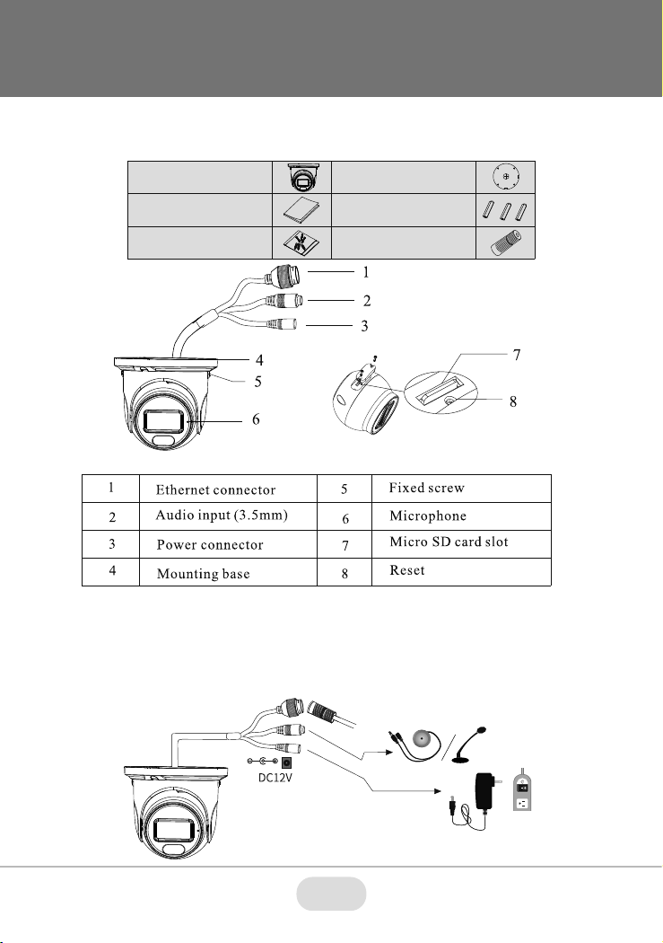
1 Ch. Audio In + Built-in MIC*
Detect (8px/ft): 232’, Observe (19px/ft): 93’, Recognize (38px/ft): 46’, Identify (76px/ft): 23’
N/A
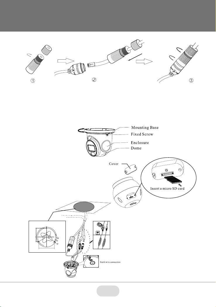
Built-in MicroSD Card Slot (up to 256GB)
CMS / Web Browser / Mobile (iOS/Android)
IE or Edge in IE mode
ONVIF
IP67
12VDC / PoE
<7W, 350mA (LEDs Off) / 600mA (LEDs On)
-22° ~140°F (-30°~60°C) / < 95% Humidity
16.26 oz / 1.01 lbs / 460g, 20.50 oz / 1.28 lbs / 580g
3.77” × 4.25” (95.7 × 108mm) Dia × H
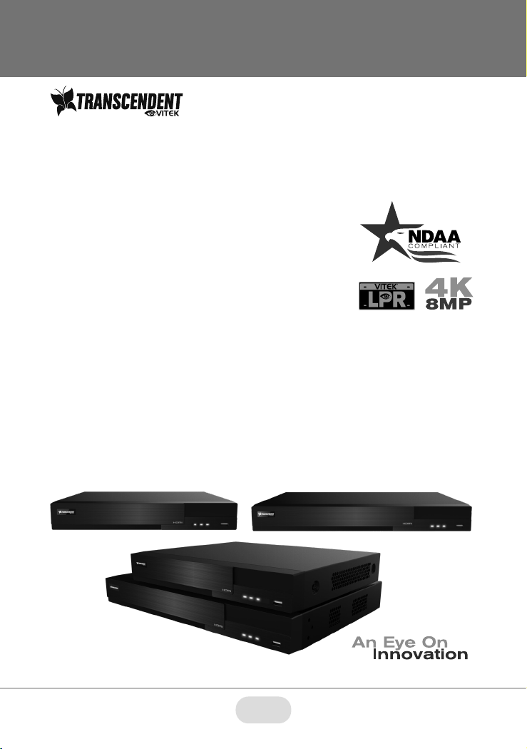
VTC-TNT5WFC-2 Detailed Specifications
*Please research local, state and federal laws regarding the implementation of audio
surveillance.

9
9
OPTIONAL ACCESSORIES
AND RELATED PRODUCTS
FOR VTC-TNT5WFC-2
VT-TWMT3
Optional Wall
Mount
VT-TJB01
Optional
Junction Box
VT-TJB08
Optional
Junction Box
VT-TPDMT-A1
Transcendent
Universal 10”
Pendant Mount.
Reqs. VT-TJB08
VT-TWMT-A1
Transcendent
Wall Mount. Reqs.
VT-TJB08
VT-TPLMT
Transcendent
Universal Pole
Adapter - Ivory
reqs. VT-TJB08
VT-TCNMT
Transcendent
Universal Corner
Adapter -
Ivory, reqs.
VT-TJB08
8.46”
6.43”
8.46”
8.47”
5.10”
6.10”
2.93”
1.46”
6.28”
2.50”
1.46”
5.83”
VT-TPDM-2
Transcendent Universal
10” Pendant Mount. Reqs.
VT-TJB01

10
OPTIONAL ACCESSORIES AND
RELATED PRODUCTS FOR
NDAA COMPLIANT
TRANSCENDENT IP CAMERAS
VT-TNR1626PN
VT-TNR414PN
VT-TNR818PN
• 8MP (4K) HDMI Output
• H.265S / H.265+ / H.265 / H.264 Video Compression
• Analytic Support Including Basic Face Detection,
License Plate Recognition, and More!
• Available in 4, 8, and 16 Channels
• Up to 24TB Depending on Model (12TB per HDD)
• PoE Support on ALL Models
TRANSCENDENT NVRs
A Standalone Solution with
Analytic Support and
NDAA Compliance!

11
11
Also Consider Vitek NDAA Compliant Wireless
Access Points to Reduce Costly Cable Installation!
VT-WAP1150 and VT-WAP2150 High Speed 5.8GHz DIP
AP / CPE Wireless Bridge w/ 8MB Storage, 64MB RAM,
150MBps transmission, and Point-to-Multi-Point (P2MP)
Topology
With high speed transmission of 150Mbps and a wireless range
of 3000ft. (VT-WAP1150) and 1.25 miles (VT-WAP2150) these
products eliminate the need for expensive and troublesome long-
distance cables in areas where CCTV monitoring and rigorous
surveillance take place. These small, lightweight and durable units are
easy to install and easy to use with an innovative and straightforward
10-button plug-and-play dip switch that facilitates the creation of a
robust wireless network without a computer. Set-up can be simply
configured for point-to-point or point-to-multipoint topology depending
on the application, with up to 128 IP group configurations!
VT-WAP1150 VT-WAP2150

28492 CONSTELLATION ROAD VALENCIA, CA 91355
WWW.VITEKCCTV.COM
Version 1.0
Feb. 2022
LIMITED PRODUCT WARRANTY
VITEK products carry a three (3) year limited warranty. VITEK warrants to the
purchaser that products manufactured by VITEK are free of any rightful claim
of infringement or the like, and when used in the manner intended, will be
free of defects in materials and workmanship for a period of three (3) years,
or as otherwise stated above, from the date of purchase by the end user.
This warranty is nontransferable and extends only to the original buyer or end
user customer of a VITEK Authorized Reseller.
The product must have been used only for its intended purpose, and not
been subjected to damage by misuse, willful or accidental damage, caused
by excessive voltage or lightning.
The product must not have been tampered with in any way or the guarantee
will be considered null and void.
This guarantee does not affect your statutory rights.
Contact your local VITEK Reseller should servicing become necessary.
VITEK makes no warranty or guarantee whatsoever with respect to products
sold or purchased through unauthorized sales channels. Warranty support is
available only if product is purchased through a VITEK Authorized Reseller.
Table of contents
Other Vitek Digital Camera manuals

Vitek
Vitek VTD-TND6FP User manual

Vitek
Vitek VT-PIRC2/H User manual

Vitek
Vitek VT-TSP8 User manual

Vitek
Vitek VT-TPTZ10HR-2T User manual

Vitek
Vitek Transcendent VTC-THB2RMS User manual

Vitek
Vitek Transcendent VTC-SMKC4 User manual

Vitek
Vitek VT-TPTZ18HR-4N User manual

Vitek
Vitek VTC-TNT8RFA4-2 User manual

Vitek
Vitek Transcendent VTC-TNB16X4MS User manual

Vitek
Vitek VT-TPTZ32HRAN-8PNS User manual
Popular Digital Camera manuals by other brands

Desert Star
Desert Star FrogEye FC-2 Operator's manual

Pentax
Pentax Optio WG-1 GPS Gray User guide manual

Konica Minolta
Konica Minolta DiMAGE Z6 instruction manual

Pentax
Pentax efina J operating manual

Panasonic
Panasonic LUMIX DMC-LF1 owner's manual

Brickhouse Security
Brickhouse Security BKC-1080DVR user guide