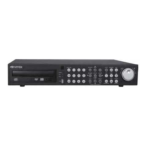
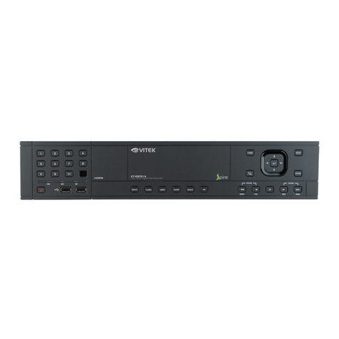
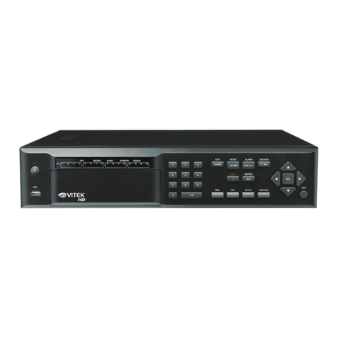
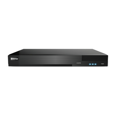
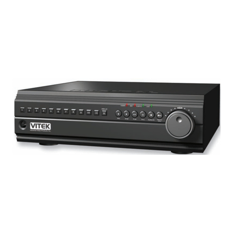
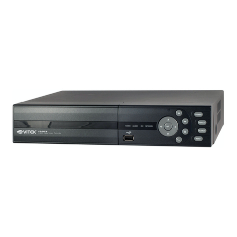
Vitek VT-HDOC4 User manual

VITEK
VT-HDOC Series
4 & 8 Channel Real-Time HD-SDI
Digital Video Recorders
• 4 or 8 HD-SDI Inputs with Full 1080p Camera Support
• Simple plug and play, point-to-point connection from camera to DVR
• VT-HDOC8: 240fps Live Display Speed at 720p/1080p & 240fps Recording &
Playback at 720p / 120fps at 1080p
• VT-HDOC4: 120fps Live Display Speed at 720p/1080p & 120fps Recording &
Playback at 720p / 60fps at 1080p
• HDMI, VGA, and BNC Outputs
• 2 Internal SATA2/SATA3 HDD Slots supporting up to 8TB (2 x 4TB HDD) using
Advanced HDD Format
• Optional External SATA Port (eSATA)
• Dual Recording Mode (Individually Selectable per Camera)
• Add 4 Analog SD Cameras (per HD input) with optional external box (VT-QHD4)
• Remote Viewing via local Software, Web Browser, and Mobile Phones (iOS/Android)
• Pentaplex Operation (Live, Playback, Recording, Backup, Network)
• Alarm In/Out
• 4 Channel Audio In
• 16 x 12 Motion Detection Grid
• Thumbnail Search
• Linear digital zoom for live and playback
• Embedded Web Server for Remote Setup & Viewing
• Up to 8 Simultaneous Network/Remote Connections
• 64 Camera Remote Viewing

VT-HDOC Series
1
TABLE OF CONTENTS
1. BEFORE INSTALLING ...............................................................................................................................3
1.1 UPDATING SYSTEM F/W ..............................................................................................................3
1.1.1 WITH A USB THUMB DRIVE..............................................................................................3
1.1.2 UPDATING FROM THE WEB MENU .................................................................................5
1.2 FRONTAND REAR ........................................................................................................................9
2. GETTING STARTED ................................................................................................................................11
2.1 CONNECTAND SWITCH ON ...................................................................................................... 11
3. TOOL BAR................................................................................................................................................13
3.1 STATUS DISPLAY ........................................................................................................................13
3.2 LOG OFF......................................................................................................................................14
3.3 MAIN MENU POP-UP...................................................................................................................14
3.4 ARCHIVE MENU POP-UP............................................................................................................14
3.5 SEARCH MENU POP-UP.............................................................................................................15
3.6 DISPLAY POP-UP ........................................................................................................................16
3.7 PTZ MODE ...................................................................................................................................16
3.8 DIGITAL ZOOM.............................................................................................................................17
3.9 LOG LIST......................................................................................................................................18
3.10 PANIC RECORD...........................................................................................................................20
4. SEARCH & PLAYBACK............................................................................................................................21
4.1 TIME / CALENDAR SEARCH.......................................................................................................21
4.2 PANORAMA SEARCH (Thumbnail search)..................................................................................23
4.3 EVENT SEARCH..........................................................................................................................25
4.4 COPY............................................................................................................................................26
5. QUICK MENU...........................................................................................................................................26
6. HOW TO CONFIGURE.............................................................................................................................30
6.1 CONFIGURING CAMERA............................................................................................................30
6.1.1 SETUP..............................................................................................................................30
6.1.2 PTZ...................................................................................................................................31
6.1.3 MOTION............................................................................................................................32
6.2 CONFIGURING DISPLAY ............................................................................................................35
6.2.1 OSD..................................................................................................................................35
6.2.2 MONITOR.........................................................................................................................36
6.2.3 SEQUENCE......................................................................................................................37
6.3 CONFIGURING SYSTEM.............................................................................................................38
6.3.1 DATE/ TIME......................................................................................................................38
6.3.2 MANAGEMENT................................................................................................................38
6.3.3 SOUND.............................................................................................................................40
6.4 CONFIGURING USER .................................................................................................................41
6.4.1 USER REGISTER.............................................................................................................41
6.4.2 USER AUTHORITY ..........................................................................................................42
6.4.3 LOG OUT..........................................................................................................................43
6.5 CONFIGURING NETWORK.........................................................................................................44
6.5.1 IP SETUP..........................................................................................................................44
6.5.2 DDNS................................................................................................................................45
6.5.3 EMAIL...............................................................................................................................45
6.6 CONFIGURING RECORD............................................................................................................47
6.6.1 CONTINUOUS..................................................................................................................47
6.6.2 EVENT..............................................................................................................................48
6.6.3 SCHEDULE ......................................................................................................................48
6.6.4 PANIC SETUP ..................................................................................................................50
6.6.5 MISC.................................................................................................................................51
6.7 CONFIGURING EVENT/SENSOR ...............................................................................................52
6.7.1 ALARM INPUT SETUP.....................................................................................................52
6.7.2 ALARM OUTPUT SETUP.................................................................................................53
6.7.3 BUZZER OUTPUT SETUP...............................................................................................54
6.7.4 E-MAIL SETUP.................................................................................................................55
6.7.5 PTZ PRESET SETUP.......................................................................................................55
6.8 CONFIGURING DISK...................................................................................................................56
7. REMOTE ..................................................................................................................................................58
7.1 WEB SERVER..............................................................................................................................58
7.1.1 CONNECT TO WEB SERVER..........................................................................................59
7.1.2 WEB CONFIGURATION PAGE ........................................................................................60
7.1.3 WEB VIEWER (Active-X)..................................................................................................61
7.2 DDNS SERVER............................................................................................................................72
7.2.1 HOW TO REGISTER........................................................................................................72
7.2.2 REGISTER........................................................................................................................72
7.2.3 Input DVR information.......................................................................................................74
7.3 DVR MANAGER...........................................................................................................................75
VT-HDOC Series
2
7.3.1 INSTALLATION.................................................................................................................75
7.3.2 EXECUTION.....................................................................................................................76
7.3.3 LIVE VIDEO MONITORING..............................................................................................76
7.3.4 CONNECTION MANAGER...............................................................................................77
7.3.5 LIVE VIDEO WINDOW .....................................................................................................79
7.3.6 PLAYER............................................................................................................................83

VT-HDOC Series
3
1.BEFORE INSTALLING
• Installation should be carried out only by qualified personnel and in accordance with electrical regulations in
force.
• The DVR must be placed on a stable surface or mounted in an approved cabinet. Adequate ventilation must
be provided, taking particular care not to block any of the air vents on the DVR.
• Adequate protection against lightning strikes and power surges must be installed to prevent damage to the
DVR.
• Any safety warnings on the DVR and in these instructions must be adhered to.
• If cleaning is necessary, shutdown the DVR and disconnect the power source first. Use a soft dry cloth only
–never use an abrasive cleaner.
• Do not attempt to service or repair the DVR as opening or removing covers may expose dangerous voltage
or other hazards. Refer all servicing to qualified service personnel
1.1 UPDATING SYSTEM F/W
1.1.1 WITH A USB THUMB DRIVE
Steps to upgrade the firmware via USB Thumb Drive:
Verify the current F/W version
Prepare new F/W in the USB thumb drive
Do the upgrading process
1.1.1.1 How to verify the F/W version
Check the F/W version provided and the F/W version currently used in the system. From the MANAGEMENT
section under the SYSTEM menu, you can see the current version of F/W.

VT-HDOC Series
4
The ‘1.04D’in the file name is the F/W version number.
Please avoid updating if the version number of F/W file is lower than the current F/W
version.
1.1.1.2 Preparing new F/W in the USB thumb drive
All the required F/W files should be copied under the ‘dvr’folder. Refer to the following steps:
Plug the USB thumb drive into a PC.
Make a ‘dvr’folder on the root directory on the USB thumb drive.
The characters, ‘d’,’v’,’r’, in the folder name have to be in lower case not in capital.
Copy the released F/W zip file into the ‘dvr’folder in the USB thumb drive.
Extract the zip file under the ‘dvr’folder. Finally all files shouled be located under the ‘USB
thumb drive\dvr’. Refer to the below picture.
Please remove the USB from the PC via Windows ‘Safe Remove Hardware and Eject Media’
feature.
1.1.1.3 Upgrading System
How to update the firmware:
Prepair USB dirve (format in fat32) and create folder with the name “dvr” download updated
firmware from http://vitekcctv.com/Downloads.asp into “dvr” folder
Cycle the DVR’s power (turn DVR Off then On and boot up)
Plug the prepared USB thumb drive in the USB port of DVR. Only the upper USB port in the
Front panel of DVR is allowed to update the F/W.
Enter the DVR menu and select “SYSTEM” then “MANAGEMENT”
Select “F/W UPGRADE” and the following image will display

VT-HDOC Series
5
Select “OK” and the following image will display
The updating process can take from 1 to 10 minutes.
Don’t remove the USB thumb drive during update.
Don’t’ turn the DVR off during update.
When the update is completed the DVR will reboot
Remove the USB thumb drive from the DVR.
1.1.2 UPDATING FROM THE WEB MENU
Using the web GUI to update the system F/W remotely:

VT-HDOC Series
6
For more information on how to access the web GUI, refer to section 7.1, ‘WEB SERVER’of
this user’s guide.
Log in to the web GUI
Go to ‘SYSTEM’then ‘SYSTEM MANAGEMENT’. Refer to the below picture.
Click the ‘F/W UPGRADE’button
In ‘F/W Update’ pop-up, click the ‘BROWSE’button locate and select the firmware.
Choose the provided F/W files which has the file extenstion ‘tar.gz or tgz’.
Click the ‘UPLOAD’button to upload the F/W to the system.
After the firmware has uploaded, the system will be ready for the update. Click the ‘START’
button to begin the updating processes.
During the update, the progress will be displayed (see below).

VT-HDOC Series
7
When the 1st stage of updating has finished, [COMPLETE] will be displayed, and the system will
reboot automatically.
After the automatic reboot, the 2nd stage of updating will start from the DVR (with the web
connection closed).
The 2nd stage updating progress will be shown on the DVR (see following picture).

VT-HDOC Series
8
When the whole update is completed, the DVR will restart.
Turning off the power during any stage of the F/W updating process will cause damage to
the system.

VT-HDOC Series
9
1.2 FRONT AND REAR
1 2 3 4
5
6 7 8
9
10
11
12
13
14
15 16 17
18
19
20
21
22
23
[Front Type]
1. DVR Model
2. STATUS LED
Displays the information of the DVR (Stand –By),
Record / HDD read/write and Network transmission.
3. IR RECEIVER
Infrared signal receiver for the IR remote controller.
4. CHANNEL SELECT / NUMERIC KEYPAD / MULTI
Selects the desired channel and show it with the full scale.
Enter the number or numbers required to be input,
Password, IP address, Time & Date and Etc.
[ ]Dot symbol for the input of IP address.
[ ]Back Space, deletes and moves character to
the left. Toggles between various multiple displays. 4
channel-splits screen display.
5. FRONT USB 1.1 / 2.0 PORT
USB 2.0 ports. Supports functions such as ‘Copy to
USB storage’, ‘F/W Upgrade’, Etc.
USB 1.1 ports. Supports ‘Mouse Operation’
6. SPOT MONITOR / ESC
Calls and gets into the main menu.
Returns to previous menu screen.
Exits from various function and menu screens.
7. Tool Bar / UP
Calls and gets into the Tool Bar.
Tilts up in PTZ control mode.
Move the cursor up in the menu.
8. FUNCTION
If you press “Function Key”, function list of DVR will be
displayed. If you press “Function Key + Tool Bar / Up
Key”, video out resolution of HDMI / VGA will be changed.
9. SPOT AUTO SEQUENCE / LEFT
Pans left in PTZ control mode.
Moves the cursor left in the menu screen.
10. DIGITAL ZOOM
Enters digital zoom mode.
11. INFO
Executes the selected function in the menu screen or
enters the selected submenu.
Accesses the status window from the live screen.
12. INSTANT PLAYBACK
If you press the “Instant playback”key, instant playback
will start from the present time. In multi-screen mode,
channel number 1 will be displayed by default. At full
screen mode, the selected channel will be displayed on
playback.
13. AUTO SEQUENCE
Activates and deactivates the automatic channel
sequence.
14. PTZ
Enters PTZ control mode.
15. PLAY / PAUSE
In playback mode, Pause / Play key will toggle.
16. REVERSE FAST
In playback mode, max X 120 reverse playback speed
supported.
17. FAST
In playback mode, max X 120 forward playback speed
supported.
18. PANIC RECORD
Activates the panic record mode.
19. KEY LOCK
Activates the Key Lock mode.
20. REVERSE SLOW
In playback mode, max X 1/120 slow reverse playback
supported.
21. ARCHIVE
Enters the archive menu screen.
22. SLOW
In playback mode, max X 1/120 slow forward playback
mode supported.
23. SEARCH
Enters the search menu screen.

VT-HDOC Series
10
[VT-HDOC4 Rear Connections]
[VT-HDOC8 Rear Connections]
1. Power Switch
Switch to turn the DVR ON & OFF.
2. eSATA
External SATA port.
3. VGA Output (Video Graphic Array)
15-pin D-sub connector for the analog VGA output.
4. Audio Inputs
RCA connectors for the audio signal inputs. (Line In)
5. Power In
DC Power socket.
6. Alarm(Sensor) Inputs, RS-485, and Relay Output
Alarm inputs x 4
RS-485 Signals. (G: Ground, D+: RX/TX + signal, D-: RX/TX-
signal)
Relay output for the relay 1 (NO: Normal Open, NC:
Normal Closed, CM: Common)
7. DIGITAL VIDEO OUT
HDMI video output for the main monitor.
8. RJ-45 Ethernet Port
10/100 Base –T, RJ-45 port for network
connection.
9. Main Monitor Output
Composite video output for the main monitor.
(BNC)
10. Audio Output
RCA connector for the audio signal output. (Line
Out)
11. Video Inputs
HD SDI DVR: HD-SDI video inputs for each
camera

VT-HDOC Series
11
2.GETTING STARTED
2.1 CONNECT AND SWITCH ON
Connect HD cameras to camera inputs on the back of the DVR.
Connect one or more monitors to the DVR using HDMI, VGA, CVBS.
Connect power to the DVR. Press the power button on the back panel of the DVR to power on the DVR.
[Logo Image]
[Loading System]
As the system boots up, you can view the loading process (see above).
After startup diagnostics are complete, the operator must log-on to the system. The default user name is
“ADMIN”. Using the mouse or channel selection buttons, key in the default password of “1234”and press
the enter button

VT-HDOC Series
12
[Log In]
[Live video mode]
The DVR begins normal operation and shows the default display of all 4 channels. The Tool bar at the bottom
of the screen shows current time and date. Tool bar includes Log In-Out, Menu, Archive, Search, Display, PTZ
& Zoom control, log along with panic record.

VT-HDOC Series
13
3.TOOL BAR
You can view the following Tool Bar when you move the mouse to the bottom of screen or press the “Tool bar
button”on the front panel.
3.1 STATUS DISPLAY
You can check the Current time / Network connection/ USB storage connection/ Auto sequence/ HDD location
currently recorded.
: Shows current time.
: Shows Network connection.
: Shows USB Storage or ODD Drive connection
: Shows Auto sequence Auto Sequence
: Shows HDD location which is currently recorded.
: Shows the selected default audio channel.

VT-HDOC Series
14
3.2 LOG OFF
There are two ways to log off. One is a manual log off, and the other is an automatic log off after the
configured time has passed (between 1 and 99 minutes).
[Log-Off by using TOOL BAR]
Press the LOG OFF button to log out the current user.
Once the user has logged out, you can view the log entry in the log window .
In addition, you can configure the automatic log off feature in the Menu Setup:
Menu SetupUserLogOut
3.3 MAIN MENU POP-UP
Press the main menu button to bring up the DVR’s main menu POP-UP.
3.4 ARCHIVE MENU POP-UP
Press the Archive menu button to bring up the Archive menu pop-up
.

VT-HDOC Series
15
3.5 SEARCH MENU POP-UP
To search for a particular section of recorded footage, press the SEARCH button.
To protect unauthorized viewing of footage, only authorized users can playback footage.

VT-HDOC Series
16
3.6 DISPLAY POP-UP
To configure the display mode, press the display button.
You can select Quad / Single/ Auto sequence by selecting the item in pop-up menu.
: Single Screen Mode.
: Quad Screen mode.
: Auto Sequence
3.7 PTZ MODE
When in quad display mode, the PTZ control panel will be opened for the selected camera (camera that is
highlighted). If there is no highlighted camera, the PTZ control panel is opened for controlling camera 1.
In single display mode, the PTZ control panel is opened for the currently displayed camera.

VT-HDOC Series
17
1 : Select channel for PTZ control .
2 : Display PTZ control parameters which are set under the ‘DETAIL’of PTZ menu settings
3 : Number to configure Preset .
4 : Select current screen as Preset.
5 : Move to configured Preset Number.
6 : Control the value of Zoom/ Focus/ Iris.
7 : Move the PTZ camera to Left/ Right/Top/Bottom
8 : Move to the Home position of PTZ camera.
3.8 DIGITAL ZOOM
There are two ways to digitally zoom:
Select the Zoom button on the Tool bar.
Click and drag with the mouse
[Zoom by using the TOOL BAR]
Desired camera should be at Full screen mode, and then select the Zoom button.
NOTE: When selecting the Zoom button while on quad display mode, channel 1 is automatically displayed.

VT-HDOC Series
18
1 : You can move Zoom Box
: If you press this button, you can control zoom box by 5 levels.
2 : Currently Zooming screen.
[Zoom by using the Mouse]
At full screen mode, you can select the area to zoom in/out by clicking/holding the left mouse button and
dragging. Clicking on the zoomed screen will return to the original screen.
Digital Zoom is supported for both Live / Play modes.
Digital Zoom is only supported at Full screen mode.
3.9 LOG LIST
You can view the log list by selecting log list button on the Tool bar.

VT-HDOC Series
19
1 : Log item number (ordered by date from the most recent. ( Max 10,000 can be recorded)
2 : Date / Time
3 : Log list
Items listed in log list.
Menu Changed
Power ON/OFF
Panic Record ON/OFF
Log In / Off
Client Connect / Disconnect
Time Set: Clock is set by user
Time Adjust: Clock is adjusted by the NTP
Copy: The recorded data is copied out.
ENV Load: Menu setting is loaded from the external storage such as USB stick.
ENV Save: Menu setting is saved to the external storage such as USB stick.
HDD Bad Sector: Bad Sector of HDD or similar access failure happened
HDD Error: Error happened during the HDD I/F but HDD still can be accessed.
HDD Fail: Impossible to recognize or access to HDD any more.
Fan Error:
This manual suits for next models
2
Table of contents
Other Vitek DVR manuals

Vitek
Vitek VT-DVR16000 User manual

Vitek
Vitek VT-SRE Spire Elite User manual

Vitek
Vitek VT-TNR Series User manual

Vitek
Vitek VT-EHL Series User manual

Vitek
Vitek CHRONO - User manual

Vitek
Vitek VT-H41 User manual

Vitek
Vitek XL User manual

Vitek
Vitek VT-H Series User manual

Vitek
Vitek VT-SRL User manual

Vitek
Vitek SAGA ST-H User manual

Vitek
Vitek SAGA VT-ST1620 User manual

Vitek
Vitek VT-HD2x8 User manual

Vitek
Vitek VT-DVR04 User manual

Vitek
Vitek MEG SERIES User manual

Vitek
Vitek VT-H Series User manual

Vitek
Vitek VT-TNR414PL User manual

Vitek
Vitek VT-EH Series User manual

Vitek
Vitek Transcendent Series User manual

Vitek
Vitek VT-EH Series User manual

Vitek
Vitek VT-TNR414P User manual