Vitrolife Octax LaserShot M User manual

1
User Manual Laser Systems version 7
Recommended use of Laser Systems
January 2021, Version 7
Octax LaserShot MTM
Octax NaviLase®
User Manual

2User Manual Laser Systems version 7
© 2020 Vitrolife GmbH. All rights reserved.
Distribution and reprinting of this document, use and communication of its
contents is not permitted without written authorisation from Vitrolife GmbH.
This user manual covers both the usage of the static LaserShot M and the
NaviLase. Sections referring to dynamic laser system NaviLase are explicitly
intended for users of this system.
You may copy this for internal use only, not for publishing.
The Vitrolife logotype is a trademark of Vitrolife Sweden AB, registered in
Europe, the U.S. and other countries.
Vitrolife Sweden AB
Box 9080
SE-400 92 Göteborg
Sweden
Tel: +46-31-721 80 00
Vitrolife GmbH
Dr.-Pauling-Str. 9
84079 Bruckberg
Germany
Tel: +49 (0)8765-939900
For the sake of convenience the Octax LaserShot or Octax NaviLase will be
referred to as LaserShot or NaviLase in this user manual.

3
User Manual Laser Systems version 7
Intended Use for Octax LaserShot M and NaviLase
For use in assisted reproduction procedures to ablate or drill the zona pellucida of an oocyte or embryo
to facilitate assisted hatching or recovery of cells for pre-implantation genetic diagnosis. The device can
also be used on blastocyst stage embryos for biopsy of trophectoderm cells for pre-implantation diagnosis
procedures, blastocyst collapse prior to vitrification procedures and sperm viability testing.
Indications for use Octax LaserShot M and NaviLase
Opening of the zona pellucida of human embryos for the purpose of assisted hatching by use of the Octax
LaserShot M or NaviLase system can be helpful in patients whose embryos do have an unusually thick
or hard zona pellucida. Biopsy of polar bodies from human oocytes or of selected cells from embryos by
use of the Octax LaserShot M or NaviLase system for the purpose of subsequent genetic analysis can be
helpful in patients in case of suspected or proven genetic disorder and/in case of suspected aneuploidy of
their oocyte(s). Blastocyst collapse by use of the Octax LaserShot M or NaviLase system can be helpful for
vitrification of blastocyst stage embryos that are in an expanded state. Sperm viability testing by use of the
Octax LaserShot M or NaviLase system allows to identify viable sperm, potentially able to fertilize an oocyte, in
patients with 100 % sperm immotility.
Contraindications for Octax LaserShot M and NaviLase
At present there are no known cell-specific contraindications, i.e. there are no morphological or other cell
indicators for oocytes, embryos ans sperm cells, that are contraindications for using the Octax LaserShot M
and NaviLase System. Contraindications on the patient side regarding Assisted Hatching or biopsy of oocytes
or embryos are left to the judgement of the physician and are related to the patient or the number of oocytes
or embryos available. There are no patient-related contraindications for sperm viability testing. The Octax
LaserShot M and NaviLase System does not have any influence on treatment related contraindications.
Side effects Octax LaserShot M and NaviLase System
When using the laser systems not according to their intended use, there is a risk of partial damage in the
cytoplasm due to heat and degeneration of the cell treated. This is especially the case when the laser beam
is directly focussed or applied to a cell. When using the NaviLase system in multi-pulse mode and intentional
or unintentional movement of the oocyte or embryo treated during the application of the laser beam, there is
a chance that the laser interacts with non-defined areas of the cells and damage to the cells. Laser energy
which is absorbed by medium causes a temperature increase. When releasing twenty laser pulses at 10 ms
pulse length using a 150 mW laser beam, a calculated energy of 30 mJ is transferred to the medium. In an
isolated media droplet of 20 μl volume this amount of energy, evenly spread over the volume, would cause
a temperature increase of 0.36°C. When using the laser systems for sperm viability testing, using the laser
beam repeteadily and directly on the sperm head may damage the functionality of proteins located in the
sperm head.

4User Manual Laser Systems version 7
Intended user group
Healthcare professionals, typically medical technical assistants (MTA) or clinical embryologists. The user has
to have at least basic experience in working in an IVF laboratory, especially with one or all of the procedures in
which the use of a laser system is potentially indicated, e.g. ICSI, Assisted Hatching, Biopsy, Vitrification.
Intended patient target groups
Female and Male patients in the age group below a maternal age of 60 that have failed to achieve a clinical
pregnancy after 12 months or more of regular unprotected sexual intercourse and / or patients with a specific
disease or genetic predisposition in the male or female that require ART in order to enable pre-implantation
diagnosis of the chromosomal or genetic constitution of their oocytes or embryos.
Intended clinical benefits to patients
The intended clinical benefits apply to patients who undergo a treatment in the field of assisted reproduction
with the aim to achieve a clinical pregnancy. Ablation or drilling of the zona pellucida of an oocyte or embryo
facilitates assisted hatching of the embryo prior implantation and can benefit the clinical outcome by better
implantation or live brith rate. In regard to the recovery of cells (polar bodies or blastomeres or trophectoderm
cells) for pre-implantation genetic diagnosis, the benefit of the laser is to facilitate the procedure, whereby
reducing the time of exposure of oocytes or embryos to unfavorable culture conditions. For blastocyst
collapse prior vitrification the application of the laser supports better survival rates after vitrification / warming,
which increases the total number of embryos available for consecutive transfers. The identification of viable
spermatozoa among immotile spermatozoa by the laser technqiue has a beneficial effect on fertilization rates,
which are connected to the clinical outcome.

5
User Manual Laser Systems version 7
Contents
Definitions 7
Warnings 7
Precautions 11
Electromagnetic Compatibility (EMC) 12
Electromagnetic Immunity 13
Symbol Glossary 15
Part I: Introduction 16
Introduction 16
Key Features of the LaserShot M/
NaviLase System 16
Working with LaserShot M / NaviLase
and EyeWare 16
Working Principle 17
Manipulation of the Zona Pellucida
using LaserShot M / NaviLase 18
Application notes for Laser Shot M
and NaviLase 19
Setting up LaserShot M / NaviLase 22
System Components 23
The Laser Systems 26
Part II: Working with LaserShot M /
NaviLase 28
Control of the Laser by
EyeWare Software 28
Installation Requirements 29
System Components 29
Setting up EyeWare Software 30
Main concept and workflow 31
Structure of EyeWare 32
Video Page with Laser Targeting
Feature 33
Calibration of the Hole Size Predictor 34
The Full Screen Mode: LaserShot M
and dynamic operation of NaviLase 41
Quick File Page for Rapid and
Temporary Storage of Images 49
The Quick File Toolbar 50
Compare Images Page 50
Image Page with Measurement Feature 50
Measurement Toolbar 51
Storage Wizard for Associating Images
with Patients 53
The Database Page for Managing
Data Sets 56
The DatabaseToolbar 57
Report Page for Printing Examination
Results 58
The Report Page Toolbar 59
Getting Started 60
Starting Eyeware Software 69
Laser Aiming Verification Procedure 60
Relationship between irradiation time
and opening size 62
How to determine the “default pulse
length setting" and verify the calibration
of the Hole Size Predictor 62
Important Notes on Laser Irradiation
Time 63
Variation of the Laser Drilling Position
and Strength 65
Closing Eyeware Software 65

6User Manual Laser Systems version 7
Part III: Additional Information 66
Advanced Image Handling Functions 66
Open Image and Save Image Dialog 66
Program Settings 68
Camera Settings 70
Generating Support Request Data 71
Maintenance 72
Cleaning and Disinfection 72
Troubleshooting Guide 74
Decommissioning of
LaserShot M / NaviLase 76
Customer Service 76
Part IV: Quick Guide 77
Laser Aiming Verification Procedure 77
Hole Size Predictor Adjustment 78
NaviLase Reset 79
Working Principle LaserShot M
- NaviLase 80
Taking Snapshots 81
Part IV: Appendix 82
Target Pointer 82
Laser Module Specifications/Labeling 87
Related Products 88
Contact and support rear side
Contents

7
User Manual Laser Systems version 7
This symbol denotes important information regarding the correct
treatment of cells and the proper use of the laser. Please read all
warnings carefully before treating any embryos or oocytes to ensure
safe application and optimal results.
EYE SAFETY OF THE OPERATOR
Eye safety of the operator is guaranteed under normal operation
of the LaserShot M and NaviLase, and in a situation when user
removable parts may be missing. However, do not disassemble
or uninstall the LaserShot M or NaviLase system and watch the
beam employing optics. Any installation / deinstallation of hard- and
software, respectively, is strictly reserved to trained and certified
service personnel authorized by Vitrolife GmbH.
This symbol denotes important cautions. Please read all
precautions before treating any embryos or oocytes to ensure safe
and optimal results.
This symbol denotes important additional information regarding the
laser device and treatment of cells.
ABOUT THIS MANUAL
The procedures described in this manual concern a particular
device installed by Vitrolife GmbH authorized personnel at a
designated location. The LaserShot M or NaviLase devices must
be operated by trained personnel according to the instructions
contained in this user manual.
LASER
The laser of the LaserShot M and the NaviLase system are
classified as a class 1M laser. Class 1M lasers emit in the
wavelength range from 302,5 nm to 4000 nm.
Laser Radiation, do not view directly with optical instruments.
warnings
Definitions
To avoid the risk of electric shock, this equipment must only be
connected to a supply mains with protective earth.
8User Manual Laser Systems version 7
INTEGRITY OF THE ELECTRO-OPTICAL SYSTEM
Maintenance of microscope components, wrong handling of the
microscope or strong displacement of the electro-optical system,
e. g. by mechanical shock can result in an incorrect position of the
beam splitter system, the magnifier lens, the camera, and the turret,
respectlively. As a result of any of the above, aiming of the laser may
no longer correspond to the crosshair position displayed at the video
image and damage to embryos may occur if the laser is used in this
condition. After maloperation of the microscope, repeat the Laser
aiming verification procedure or contact Technical Service.
INCORRECT LASER AIMING
Failure to follow the laser aiming verification procedure could result in
wrongly located openings and therefore may damage the treated oocyte
or embryo.
MULTIPLE OR SMALL OPENINGS
Only a single opening should be made in the zona pellucida. Multiple
openings or openings that are too small may prevent embryo hatching
and/or lead to abnormal embryo development.
DEVELOPMENT STAGE
Laser assisted hatching should only be performed on 4-8 cell embryos.
Effects of laser assisted hatching on embryos of later developmental
stages (> 8 cell stage) are not known.
LONG-TERM FOLLOW UP
To date there are no known reports showing a greater occurrence
rate of major or minor defects in children born after laser assisted
hatching of embryos. Long-term follow-up data on children derived
from embryos treated by laser assisted hatching does not yet exist.
A follow-up study of 134 such babies found no increase in the major
congenital malformations, chromosomal aberrations or minor congenital
malformations between the laser assisted hatching treated group and
all deliveries at their hospital. (Kanyo, K., Konc, J. “A follow-up study of
children born after diode laser assisted hatching.” European Journal of
Obstetrics and Gynecology. 110: 176-180 (2003)).
Only use the 25x laser lens when using LaserShot M or NaviLase. Use
of other objectives for laser treatments may damage the embryo.

9
User Manual Laser Systems version 7
INSTALLATION AND MAINTENANCE
Installation and repair of the LaserShot M or NaviLase shall only be
carried out by a person certified by Vitrolife. The LaserShot M must
remain on the microscope and at the location where it was installed.
If a LaserShot M or NaviLase is disconnected and/or moved without
supervision by a person certified by Vitrolife the LaserShot M or
NaviLase will no longer be approved for clinical use and the warranty
may be voided.
If the LaserShot M , NaviLase or parts of it are modified, appropriate
inspection and testing must be conducted by a Vitrolife certified
person to ensure continued safe use.
A preventative maintenance of the laser is recommended every
12-18 months to ensure optimal performance of the laser.
ELECTROMAGNETIC COMPATIBILITY
The LaserShot M and Navilase have been tested and found to com-
ply with the limits for medical devices to the IEC 60601-1-2:2014/
EN 60601-1-2:2014 for electromagnetic compatibility. These limits
are designed to provide reasonable protection against harmful inter-
ference in a typical medical installation.
This equipment generates, uses and can radiate radio frequency
energy and, if not installed and used in accordance with the instruc-
tions, or if connected to material not certified by Vitrolife, may cause
harmful interference to other devices in the vicinity. However, there
is no guarantee that interference will not occur in a particular instal-
lation. If this equipment does cause harmful interference to other
devices, which can be determined by turning the equipment off and
on, the user is encouraged to try to correct the interference by one or
more of the following measures:
•Reorient or relocate the receiving device.
•Increase the separation between the equipment.
•Connect the equipment into an outlet on a circuit different from that
to which the other device(s) are connected.
Consult the manufacturer, their representative or dealer for help.
WARNING: The use of accessories and cables other than those
supplied by Vitrolife, may result in increased emissions or decreased
immunity of the ME equipment or ME system.
WARNING: Portable RF communications equipment (including
peripherals such as antenna cables and external antennas) should be
used no closer than 30 cm (12 inches) to any part of the LaserShot
M , including cables specified by the manufacturer. Otherwise, deg-
radation of the performance of this equipment could result.

10 User Manual Laser Systems version 7
CONNECTION TO EXTERNAL EQUIPMENT
To guarantee basic safety and compliance with elevant EC standard
(i.e. EN 60601-1 – Part 1 for medical electrical equipment) and
essential performance, this equipment must only be connected to
computer equipment certified by Vitrolife, and connection must only
be made using certified cables.
CONNECTORS
Do not disconnect the USB cable connector unless instructed to do
so by qualified support personnel.
The recipient end user of the LaserShot M / NaviLase systems should
not unpack and install it upon receipt. Unpacking, installation, setup
and end-user training of LaserShot M / NaviLase systems must be
carried out by appropriately qualified technical staff authorized by
Vitrolife GmbH.
TE MODE: RESTRICTIONS IN USE
The TE mode must only be used by experienced users trained in doing
trophectoderm biopsies. The laser puls(es) can assist the release of
mechanically stretched intracellular bonds between trophectoderm
cells for biopsy. The TE mode must never be applied to the zona
pellucida.
LIMITED WARRANTY
Vitrolife warrants the LaserShot M or NaviLase to be free from defects
in materials and workmanship for a period of two (2) year from the day
of shipping.
The limited warranty shall terminate immediately if installation,
maintenance, repair or relocation of the laser system is carried out by
other than Vitrolife certified personnel.
•The limited warranty shall not apply to damage resulting from:
• Failure to perform routine maintenance in accordance with this User
Manual;
• Accident, abuse, misuse, or misapplication of the device;
• Use and operation that does not comply with instructions provided in
the User Manual;
• Normal wear and tear.

11
User Manual Laser Systems version 7
INFLUENCE OF Z-POSITION OF THE OOCYTE/EMBRYO ON
DRILL OPENING SIZE
Inappropriate Z-positioning will result in smaller drill holes and in
reduced laser beam quality. It is recommended to keep the cell near the
bottom of the culture dish during laser treatment.
precautions
To minimize the risk of damage to the oocyte or embryos, administer
as few laser pulses as possible at the lowest energy levels possible to
achieve the prescribed effect.
Direct the laser beam towards a section of the zona pellucida where the
adjacent perivitelline space is widest or next to an area of fragmentation.
A holding pipette should be used during laser treatment to minimize the
risk of embryo movement.
REPEATED LASER SHOTS
Repeated laser shots to the same position of the embryo could result in
an increased risk of embryo damage. In case of risk of applying repeated
laser shots to the same position of the embryo the laser action can be
immediately stalled by pressing the emergency stop button.
INFLUENCE OF TEMPERATURE ON DRILL OPENING SIZE
When using a heated stage during zona manipulation, make sure that
it has been set to the correct temperature. Inappropriate temperature
settings will lead to unexpected drill hole sizes. Lower temperatures
result in smaller openings, while higher temperatures cause openings of
excessive sizes that may lead to embryo damage.
The user of the laser system should report any serious incident that has
occurred in relation to the device to Vitrolife and the competent authority
of the Member State in which the user is established.
"Serious incident" means any incident that directly or indirectly led,
might have led or might lead to any of the following: (a) the death of a
patient, user or other person, (b) the temporary or permanent serious
deterioration of a patient's, user's or other person's state of health, (c) a
serious public health threat.

12 User Manual Laser Systems version 7
Electromagnetic
Compatibility (EMC)
The below table contains the applicable information required for CISPR11 systems:
Guidance and manufacturer’s declaration – Electromagnetic emissions
LaserShot M and NaviLase laser systems is intended for use in the electromagnetic environment
specified below. The customer or the user of LaserShot M and NaviLase laser systems should
assure that it is used in such an environment
Emissions test
RF emissions
EN/CISPR 11
Radiated and
Conducted
Emission
Harmonic emissions
IEC 61000-3-2
Voltage fluctuations
flicker emissions
IEC 61000-3-3
Compliance
Class A
Group 1
Class A
Passed
Electromagnetic environment - guidance
LaserShot M and NaviLase laser systems
use RF energy only for their internal function.
Therefore, their RF emissions are very low and
not likely to cause any interference in nearby
electronic equipment.
The emissions characteristics of this
equipment make it suitable for use in
industrial areas and professional
healthcare facility environment (CISPR 11
class A). It it is used in a residential
environment (for which CISPR 11 class B
is normally required) this equipment might
not offer adequate protection to
radiofrequency
communication services. The
user might take mitigation measures, such
as relocating or re-orienting the equipment.

13
User Manual Laser Systems version 7
Electromagnetic Immunity
Guidance and manufacturer’s declaration – Electromagnetic immunity
LaserShot M and NaviLase laser systems is intended for use in the electromagnetic environment specified below. The customer
or the user of LaserShot M and NaviLase laser systems should assure that the used in such an environment
Immunity test
Electrostatic
discharge (ESD)
IEC 61000-4-2
Electrical fast transient
/burst IEC 61000-4-4
Surge
IEC 61000-4-5
Voltage dips, short
interruptions and
voltage variations on
power supply input
lines IEC
61000-4-11
Power frequency
(50/60 Hz)
Magnetic field IEC
61000-4-8
Compliance
contact ± 8 kV
air ± 2 kV, ± 4 kV, ± 8 kV, ± 15 kV
AC Mains +/- 2kV
Signal +/- 1 kV 100 kHz repetition
frequency
Line-to-line ± 0.5 kV, ± 1 kV Line-To-Earth
± 0,5kV, ±1kV, ±2kV
0 % UT; 0,5 cycle
At 0°, 45°, 90°, 135°, 180°, 225°, 270° and 315°
0 % UT; 1 cycle
and
70 % UT; 25/30 cycles
Single phase: at 0°
and
0 % UT; 250/300 cycle
30 A/m
50 & 60 Hz
Electromagnetic
environment - guidance
Floors should be wood, concrete or ceramic tile.
If floors are covered with synthetic material, the
relative humidity should be at least 30%
Mains power quality should be that of a typical
commercial or hospital environment
Mains power quality should be that of a typical
commercial or hospital environment
Mains power quality should be that of a typical
commercial or hospital environment
If the user of LaserShot M and NaviLase laser
systems requires continued operation during
power mains interruptions, it is recommended
that the incubator be powered from an
uninterruptible power supply or battery.
No degradation of the essential performance was
observed and EUT remains safe during the test.
Power frequency magnetic fields should be at
levels characteristic of a typical commercial or
hospital environment.

14 User Manual Laser Systems version 7
Immunity test
Conducted RF
IEC 61000-4-6
Radiated RF
IEC 61000 4-3
Compliance
3 V
0,15 MHz – 80 MHz
6 V in ISM and amateur radio bands
between 0,15 MHz and 80 MHz
80 % AM at 1 kHz
3 V/m
80 MHz to 2.7 GHz
Electromagnetic
environment - guidance
No degradation of the essential performance was
observed and EUT remains safe during the test in
normal operational mode and in alarm mode.
Portable and mobile RF communications equipment
should be used no closer to any part of LaserShot M
and NaviLase laser systems, including cables, than
the recommended separation distance calculated
from the equation applicable to the frequency of the
transmitter.
IMMUNITY to proximity fields from RF wireless
communications equipment IEC 61000-4-3
28 V/m
450 MHz, ±5 kHz FM, 1 kHz sinus
810 MHz, 50% PM at 18 Hz
870 MHz, 50% PM at 18 Hz
930 MHz, 50% PM at 18 Hz
1720 MHz, 50% PM at 217 Hz
1845 MHz, 50% PM at 217 Hz
1970 MHz, 50% PM at 217 Hz
2450 MHz, 50% PM at 217 Hz
27 V/m
385 MHz, 50% PM at 18 Hz
9 V/m
710 MHz, 50% PM at 217 Hz
745 MHz, 50% PM at 217 Hz
780 MHz, 50% PM at 217 Hz
5240 MHz, 50% PM at 217 Hz
5500 MHz, 50% PM at 217 Hz
5785 MHz, 50% PM at 217 Hz
The below two tables contain the applicable information required for a system other than those
specified for use only in a shielded location and for systems that are not life supporting.
Guidance and manufacturer’s declaration – Electromagnetic immunity
LaserShot M and NaviLase laser systems is intended for use in the electromagnetic environment specified below. The
costumer or the user of LaserShot M and NaviLase laser systems should assure that it is used in such an environment
NOTE 1 At 80 MHZ and 800 MHz, the higher frequency range applies.
NOTE 2 These guidelines may not apply in all situations. Electromagnetic propagation is affected by
absorption and reflection from structures, objects and people.
2 Field strengths from fixed transmitters, such as base stations for radio (cellular/cordless) telephones and land
mobile radios, amateur radio, AM and FM radio broadcast and TV broadcast cannot be predicted theoretically with
accuracy. To assess the electromagnetic environment due to fixed transmitters, an electromagnetic site survey should
be considered. If the measured field strength in the location in which the LaserShot M and NaviLase laser systems
incubator is used exceeds the applicable RF compliance level above, the LaserShot M and NaviLase laser systems
incubator should be observed to verify normal operation. If abnormal performance is observed, additional measures
may be necessary, such as reorienting or relocating the incubator.
b Over the frequency range 150 kHz to 80 MHz, field strengths should be less than 3 V/m.
15
User Manual Laser Systems version 7
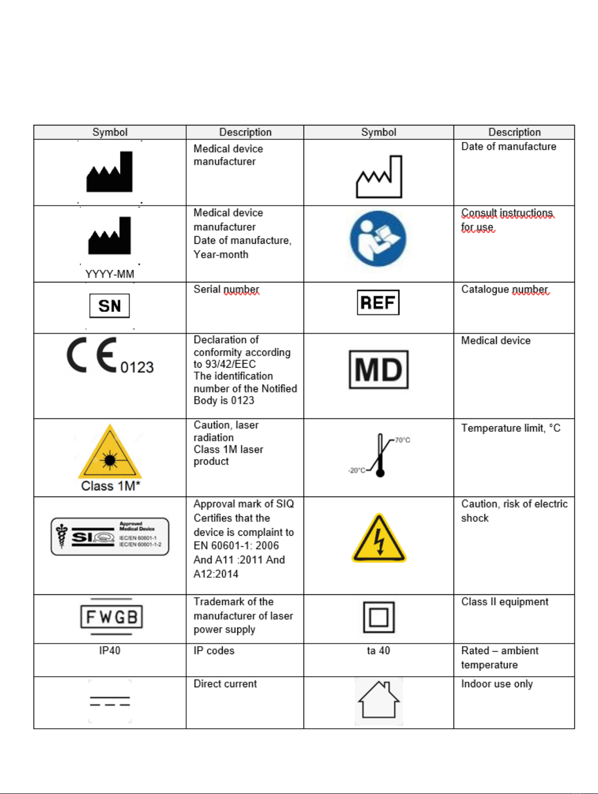
symbol glossary

16 User Manual Laser Systems version 7
Part I: Introduction
This chapter provides an outline of the key features and applications of the
LaserShot M/NaviLase system
Introduction
The laser systems for microsurgery utilized in the field of assisted reproductive technology
(ART). The laser systems can be used to manipulate the zona pellucida of oocytes or
embryos in order to assist hatching and to extract polar bodies or cells for subsequent
genetic analysis.
Key Features of the LaserShot M / NaviLase System
The LaserShot M / NaviLase system is based on an infrared laser diode emitting at a
wavelength of 1,48 μm which is coupled to an inverted microscope. The laser beam is
directed along the microscope optical axis. The spatial arrangement of lenses and mirrors
within the laser unit allows focusing of the laser beam to the image plane of the microscope
objective. In addition to LaserShot M, NaviLase includes motion elements which allow the
controlled movement of the laser beam to any position within the working field which is
visible from the camera image. The microscope should be equipped with a heating stage
to ensure optimal conditions for oocytes, zygotes and spermatozoa. The infrared 1,48 μm
wavelength emitted by the laser diode is non-mutagenic and thus, it is ideally suited for the
use in non-contact procedures in ART.
Working with LaserShot M/ NaviLase and EyeWare
The LaserShot M / NaviLase system provides an advanced laser technology for ART
featuring digital control and digital video / image processing combined with high optical and
electro-mechanical quality. Controlled by the EyeWare imaging software the LaserShot M /
NaviLase system can be intuitively used for the daily routine.
Acquired by a high resolution digital camera a live video stream of the cells is displayed at
the computer monitor. The video image is overlaid by an computer generated crosshair,
which marks the aiming position of the laser beam. A laser pulse is triggered either by
mouse or optionally by foot switch. The irradiation time of the laser is set within the user
interface of the EyeWare software.
With EyeWare not only microscopic devices, microscopic imaging and measurements
can easily be managed, but also documentation has been made very convenient. With the
database module patient data and snapshots are stored and administrated. Connection to
17
User Manual Laser Systems version 7
an external database allows importing and exporting of datasets. A predefined report with
any set of examination results can be printed after only a few mouse clicks. Datasets may be
exported to PDF-files for e-mail forwarding and to RTF-files or to CSV-files for further text or
spreadsheet program processing, respectively.
Focusing of the zona pellucida at equator level and
positioning of the oocyte or embryo
Laser activation
Selection of laser working
mode (NaviLase only)
Adjustment of pulse time / hole diameter
Triggering the laser
Manipulation of the zona pellucida
Select laser lens
Working Principle

18 User Manual Laser Systems version 7
Manipulation of the Zona Pellucida
using LaserShot M / NaviLase
The laser beam generated by the LaserShot
M / NaviLase causes a tangential thinning or
opening of the zona pellucida of oocytes and
embryos by a highly localized photo thermal
process which lyses the glycoprotein matrix.
Thereby, trench-like openings with even walls
are generated (Fig. 1) which appear circularly
shaped in a two-dimensional view. The size of
the opening can be adapted to the respective
procedure simply by varying the irradiation
time of the laser. The reproducibility of the
drilling effect is very high.
The LaserShot M / NaviLase system uses a
laser that has no known potential mutagenicity
as compared to, e. g. UV laser procedures.
Furthermore, with the laser having a relatively
low power in focus (100 mW - 250 mW)
fundamental safety studies have been
conducted. Until now no adverse effect of
the described laser procedures has been
documented. A follow-up study on 134
children born after laser assisted hatching
(LAH) was performed and revealed no
increase in the major congenital malformation
rate, no increase in chromosomal aberrations
and no difference in the minor congenital
malformation rate.
A
B
Photos courtesy CHUV, Lausanne, Switzerland
Fig. 1: Scanning electron micrographs of a laser
treated murine zygote at low magnification (A) and
at higher magnification (B).
Inform the patient about contraindications and side effects of laser
applications (see p. 3).

19
User Manual Laser Systems version 7
Alternatively, the outer layers of the zona pellucida may be ablated largely and across a wider
area, but without breaching it. This process is commonly referred to as zona thinning. An
area of 25-40% of the circumference of the zona pellucida should be thinned by contiguous
laser shots generating holes of 15–20 μm in diameter with maximum 50% overlap. The
overlapping laser shots should be positioned in a way to ablate about 50-70% of the initial
zona pellucida thickness.
Note: AH is not recommended for routine use in all ART patients.
Pictures: University of Bonn
Assisted hatching (AH)
The aim of AH is to locally weaken the zona pellucida by creating a trench along the optical
axis of the laser beam (see. Fig. 1, p.17) which appears as a hole when seen through an
inverted microscope.
To minimize the risk of damage to blastomeres, users should administer as few laser pulses
as possible at the shortest pulse lengths possible to achieve zona drilling or thinning effects.
Only a single opening should be made in the zona pellucida. Multiple openings or those that
are too small might prevent the embryo from hatching or lead to abnormal development. The
laser beam should be directed towards a section of the zona pellucida where the adjacent
perivitelline space is widest.
For AH, the drilled hole size should be approximately 1.5 times of the thickness of the zona
pellucida. A minimal invasive strategy is to create an opening by means of 2 holes with a
diameter of 20 μm, i.e. slightly larger than the zona thickness (typically 16-18 μm in human
embryos). An overlap of approximately 50% will generate the desired hole size resulting in
the formation of an oval shaped opening. (see figure C below.) Due to the 50% overlap, this
approach is robust with respect to small variations in the actual zona thickness.
Application notes for LaserShot M and NaviLase

20 User Manual Laser Systems version 7
Blastomere biopsy (cleavage stage)
The aim of cleavage stage biopsy is to retrieve 1 or 2 blastomeres from a day three embryo
for genetic analysis.
A pulse time should be selected to create an opening of about 20 μm. The embryo should
be rotated and blastomere(s) selected for biopsy should be positioned using a holding
capillary. The embryo should be held close to the bottom of the dish to maximize laser
efficiency.
An oval shaped opening should be drilled using two or three overlapping laser pulses to
open the zona pellucida for easy access of the single blastomere selected for biopsy. If two
blastomeres were selected for biopsy, the opening should be made in between the two
cells.
Trophectoderm (TE) cell biopsy
The aim of TE biopsy is to retrieve 2-10 TE cells as samples for genetic analysis. TE cells are
separated from a blastocyst stage embryo without causing damage to the inner cell mass
(ICM).
15 to 20 hours prior to biopsy, AH is performed making a small hole or channel (approx. 5
μm wide) in the zona pellucida of the embryo using 1-3 laser pulses. The opening should
be placed at the opposite side of the ICM. Typically, 5-7 TE cells will have formed a hernia,
protruding from the hole, at the time point of biopsy. This step is optional but will facilitate
the biopsy procedure.
Under the inverted microscope, a holding pipette is used to position and firmly fix the
blastocyst in a way that the herniating TE cells are facing the biopsy pipette. The blastocyst
should be hold close to the bottom of the dish to maximize laser efficiency. The biopsy
pipette should have an inner diameter of 20-30 μm.
The laser should be switched to TE mode.
For biopsy, 2-10 of the herniated TE cells should be aspirated into the biopsy pipette.
Subsequently, the aspirated TE cells should be gently pulled away from the blastocyst to
stretch and expose the intracellular junctions and minimize cell damage. Subsequently, two
or three laser pulses are applied to the intracellular junctions of the cells to be separated.
Pulling gently will completely break the intracellular junctions and the separated cells should
be aspirated into the biopsy capillary carefully. They are finally placed at some distance from
the embryo for subsequent transfer into a tube for genetic analysis.
TE MODE: RESTRICTIONS IN USE
The TE mode must only be used by experienced users trained in
doing trophectoderm biopsies. The laser puls(es) can assist the
release of mechanically stretched intracellular bonds between
trophectoderm cells for biopsy. The TE mode must never be applied
to the zona pellucida.
This manual suits for next models
1
Table of contents
Other Vitrolife Measuring Instrument manuals


