Vivax Metrotech vLocPro2 Instruction Manual

vLoc Series 2 User Handbook
(vLocPro2, vLocML2)
(English Edition)
Version 1.4


Table of Content
1. General Safety & Care Information....................................................................................... 1
1.1 Who Can Use This Equipment................................................................................................ 1
1.2 Work-site Safety...................................................................................................................... 1
1.3 Equipment Safety.................................................................................................................... 1
1.4 Batteries and Environmental Safety........................................................................................ 1
1.4.1 Alkaline Batteries (Non Rechargeable)................................................................................ 1
1.4.2 Nickel Metal Hydride Batteries (Rechargeable) ................................................................... 1
1.4.3 Lithium-Ion Batteries (Rechargeable) .................................................................................. 2
1.4.4 Lithium Metal Batteries (Non Rechargeable) ....................................................................... 2
1.4.5 General Rules Regarding Disposal of Batteries................................................................... 2
1.4.6 Transportation of Lithium-ion and Lithium Metal Batteries................................................... 2
1.5 Care of Equipment .................................................................................................................. 3
1.6 Care When Interpreting the Information Provided by the Locator ........................................... 3
1.7 American & Canadian Safety Notices ..................................................................................... 3
2. Service & Support................................................................................................................. 4
2.1 Serial Number and Software Revision Number....................................................................... 4
2.2 Distributors and Service Centers Closest to You: ................................................................... 5
3. vLocPro2 Receiver ............................................................................................................... 6
3.1 vLocPro2 Receiver.................................................................................................................. 6
3.2 Charging the Receiver Batteries ............................................................................................. 7
3.3 vLocPro2 Receiver Main Display ............................................................................................ 8
3.4 vLocPro2 Receiver Screen Shots ........................................................................................... 9
3.5 Locating Mode (Response) ................................................................................................... 10
3.5.1 Peak Response Mode ....................................................................................................... 10
3.5.2 Broad Peak Mode .............................................................................................................. 10
3.5.3 Null Mode........................................................................................................................... 10
3.5.4 Peak with Arrows Response Mode .................................................................................... 11
3.5.5 Sonde Mode ...................................................................................................................... 12
3.6 Audio..................................................................................................................................... 12
3.7 Sensitivity Control ................................................................................................................. 12
3.8 Frequency Selection ............................................................................................................. 13
3.9 Information Pushbutton (Depth & Current)............................................................................ 14
3.10 Information Pushbutton (Setup Menu) .................................................................................. 14
4. vLocML2 Receiver .............................................................................................................. 15
4.1 Introduction ........................................................................................................................... 15
4.2 Operating the vLocML2......................................................................................................... 16
4.2.1 Switching Between Configuration ...................................................................................... 16
4.2.2 Standard ............................................................................................................................ 16
4.2.3 Dedicated........................................................................................................................... 16

4.2.4 Marker Depth Estimation in Dedicated Mode..................................................................... 18
4.2.5 Dual Configuration ............................................................................................................. 19
5. Data Logging ...................................................................................................................... 20
5.1 Bluetooth............................................................................................................................... 20
5.1.1 Fitting the Bluetooth Module .............................................................................................. 20
5.2 Holux GPS Device Overview ................................................................................................ 21
5.2.1 Pairing with the vLocPro2/vLocML2 Receivers.................................................................. 21
5.2.2 Gathering Data in Active Modes ........................................................................................ 22
5.2.3 Gathering Data in Power and Radio (Passive) Modes....................................................... 22
5.2.4 Transferring Data from the Locator to a Computer ............................................................ 22
5.3 Trimble ProXT/XH ................................................................................................................. 23
5.3.1 Trimble ProXT/XH Setting up Procedure ........................................................................... 23
5.3.2 Transferring Data from the vLoc2 to a Computer............................................................... 24
5.4 MyLocator2 ........................................................................................................................... 25
5.4.1 Launch the Application ...................................................................................................... 25
5.4.2 Splash Screen ................................................................................................................... 26
5.4.3 Upload Data Files .............................................................................................................. 27
5.4.4 Software Update ................................................................................................................ 28
5.4.5 Advanced Configuration Tool............................................................................................. 29
5.4.6 Switch On/Off User Menu Settings .................................................................................... 30
5.4.7 Switching On/Off Frequency Selections ............................................................................ 31
5.4.8 Saving a Configuration ...................................................................................................... 31
5.4.9 Configuration Lock Dongle................................................................................................. 32
5.4.10 Icon Summary.................................................................................................................... 34
6. Loc-10Tx Transmitter.......................................................................................................... 35
6.1 Loc-10Tx Transmitter Overview ............................................................................................ 35
6.2 Transmitter Battery................................................................................................................ 36
6.2.1 Removing the Battery Tray ................................................................................................ 36
6.2.2 Replacing the Alkaline Battery ........................................................................................... 36
6.2.3 Rechargeable Batteries ..................................................................................................... 36
6.2.4 Re-fitting the Battery Tray.................................................................................................. 37
6.2.5 Battery Charging and Disposal .......................................................................................... 37
6.2.6 Battery Condition Indication............................................................................................... 37
6.3 Transmitting Modes............................................................................................................... 38
6.3.1 Induction Mode .................................................................................................................. 38
6.3.2 Direct Connection Mode .................................................................................................... 38
6.3.3 Clamp Mode ...................................................................................................................... 39
6.3.4 Connection Block............................................................................................................... 39
6.3.5 Frequencies and Power Output ......................................................................................... 40
6.3.6 Most Used Frequencies (Frequency Selection) Feature.................................................... 41
6.3.7 "Dual frequency" Mode ...................................................................................................... 42

6.4 Information ............................................................................................................................ 42
7. Loc-5Tx Transmitter............................................................................................................ 43
7.1 Pushbutton............................................................................................................................ 43
7.2 External Connectors.............................................................................................................. 43
7.3 Transmitter Battery................................................................................................................ 43
7.3.1 Removing the Battery Tray ................................................................................................ 43
7.3.2 Replacing Alkaline Batteries .............................................................................................. 44
7.3.3 Rechargeable Batteries ..................................................................................................... 44
7.3.4 Re-fitting the Battery Tray.................................................................................................. 44
7.3.5 Battery Charging and Disposal .......................................................................................... 44
7.3.6 Battery Condition Indication............................................................................................... 44
7.4 Display .................................................................................................................................. 45
7.5 Multi Frequencies.................................................................................................................. 46
7.6 Most Used Frequencies (Frequency Selection) Feature ....................................................... 46
7.7 Induction Mode...................................................................................................................... 47
7.8 Direct Connection Mode........................................................................................................ 47
7.9 Clamp Mode.......................................................................................................................... 47
8. Loc-1Tx Transmitter............................................................................................................ 48
8.1 Pushbutton............................................................................................................................ 48
8.2 External Connectors.............................................................................................................. 48
8.3 Replacing Alkaline Batteries ................................................................................................. 48
8.4 Rechargeable Batteries......................................................................................................... 48
8.5 Loc-1Tx Transmitter Operation ............................................................................................. 48
9. Using the vLocPro2 ............................................................................................................ 49
9.1 Using the Receiver................................................................................................................ 49
9.1.1 Line Locating ..................................................................................................................... 49
9.1.2 Depth & Current Measurement .......................................................................................... 49
9.1.3 Sonde Location.................................................................................................................. 50
9.1.4 Using the Compass Feature to Locate Sondes ................................................................. 50
9.2 Passive or Active Location .................................................................................................... 52
9.2.1 Passive Locating................................................................................................................ 52
9.2.2 Active Locating .................................................................................................................. 52
9.3 Applying the Transmitter’s Signal.......................................................................................... 53
9.3.1 Direct Connection .............................................................................................................. 53
9.3.2 Clamp (Coupler) ................................................................................................................ 53
9.3.3 Induction ............................................................................................................................ 54
9.3.4 Searching (sweeping) an Area........................................................................................... 55
9.3.5 Tracing a Buried Line......................................................................................................... 55
9.3.6 Pinpointing & Confirming the Buried Line .......................................................................... 55
9.3.7 Distorted Fields.................................................................................................................. 56
9.3.8 Measuring Depth and Current............................................................................................ 57

9.3.9 Signal Direction Precision Identification............................................................................. 58
9.4 Using the Accessories........................................................................................................... 60
9.4.1 Using the LPC Separation Filter ........................................................................................ 60
9.4.2 Using the A-frame in Fault Finding .................................................................................... 61
9.4.3 Using the Remote Antenna USB ....................................................................................... 63
10. Accessories & Options........................................................................................................ 66
10.1 A-frame (Optional)................................................................................................................. 66
10.2 Remote Antenna (Optional) .................................................................................................. 66
10.3 Loc-10Tx Vehicle Power Lead (Optional).............................................................................. 66
10.4 Loc-10Tx Outdoor Power Supply (Optional) ......................................................................... 66
10.5 LPC Separation Filter (Optional) ........................................................................................... 66
10.6 Receiver Vehicle Charging Lead (Optional) .......................................................................... 66
10.7 Sonde (Optional)................................................................................................................... 67
10.8 Clamp (Optional)................................................................................................................... 67
10.9 Lithium-ion Rechargeable Battery Pack (Standard) .............................................................. 68
10.10 Receiver Battery Charger (Standard).................................................................................... 68
10.11 USB Cable (Standard) .......................................................................................................... 68
10.12 Alkaline Battery Holder (Standard)........................................................................................ 68
10.13 Ground Stake (Standard)...................................................................................................... 68
10.14 Direct Connection Lead (Standard)....................................................................................... 68
10.15 Loc-1Tx Alkaline Battery Tray (Standard) ............................................................................. 68
10.16 Ground Spool (Optional) ....................................................................................................... 69
10.17 Banana Plugs Adapter (Optional).......................................................................................... 69
10.18 Loc-5Tx Battery Pack (NiMH)................................................................................................ 69
10.19 Loc-5Tx Alkaline Battery Tray ............................................................................................... 69
10.20 Loc-5Tx/10Tx Charger .......................................................................................................... 69
10.21 Loc-10Tx Rechargeable Battery Tray ................................................................................... 69
10.22 Loc-10Tx Alkaline Battery Tray ............................................................................................. 69
11. Glossary.............................................................................................................................. 70

1 General Safety & Care Information
Page 1 of 72
1. General Safety & Care Information
1.1 Who Can Use This Equipment
•This equipment must only be used by people suitably trained in the use of pipe and cable locators.
1.2 Work-site Safety
•Use your companies, or other applicable safety code and rules when using this equipment.
•Unless having the required authorization, license and appropriate training – do NOT make
connections to any pipe, cable or conductor.
•The equipment should not come in contact with corrosive or hazardous chemicals, or gases, dust.
•Do NOT directly connect this equipment to cables or pipes that have a potential difference to ground
of greater than 35V AC.
1.3 Equipment Safety
•Do NOT open the enclosures (housings) of either the transmitter or receiver.
•Place the ground stake firmly in the ground before connecting the cable from the transmitter.
•Do NOT hold any uninsulated portion of the connection leads & clips when the transmitter is switched
on.
1.4 Batteries and Environmental Safety
Vivax-Metrotech products use four types of batteries:
•Alkaline batteries
•Ni-MH (Nickel Metal Hydride) batteries – rechargeable
•Lithium-ion batteries – rechargeable
•Lithium metal batteries – (small non rechargeable button cells for “clock” applications)
1.4.1 Alkaline Batteries (Non Rechargeable)
•When replacing the alkaline batteries – use only the size and type specified – do NOT mix battery
types (rechargeable and alkaline).
•Do NOT mix partially discharged and fully charged cells in the same battery pack – do NOT mix old
with new.
•Never attempt to charge alkaline batteries.
1.4.2 Nickel Metal Hydride Batteries (Rechargeable)
•When using rechargeable batteries, use only the correct charging device supplied or specified by
the manufacturer. The battery pack or the battery charger will contain circuitry to manage the
charging process – other chargers (even if they have the same connector, polarity, voltage & current
rating will not have the same control circuitry and can cause damage to the product, overheating, and
in extreme cases fire or harm to the individual.
•Do NOT assume that if the plug fits it is the correct charger – a charger with the correct part number
MUST be used – just because it is a Vivax-Metrotech charger and the plug fits does NOT mean it is
the correct charger.
•Before using for the first time, charge rechargeable batteries for 6 hours. If at any time the
rechargeable batteries do NOT last as long as anticipated – discharge fully and then charge for 6
hours.
•Care should be taken when charging batteries – NEVER repeatedly recharge batteries (or turn power
off & on) without using the instrument. If used with an inverter in a vehicle – charge the product then
unplug the charger and do NOT charge again until the rechargeable batteries have been used for at
least ten minutes. Failure to do this could result in the overcharging of the battery which will shorten
the life of the battery, and could in some circumstances cause overheating or fire.
•If ever the product becomes hot during the charging process IMMEDIATELY unplug the charger and
use the rechargeable batteries for at least 10 minutes before recharging. If this reoccurs the next time
the unit is charged – return immediately to Vivax-Metrotech for repair.
•Do NOT charge batteries for prolonged periods of time without using the locator for at least 10 mins.

1 General Safety & Care Information
Page 2 of 72
Charging for prolonged period of time could overcharge the battery, reduce the battery life and in
extreme circumstances cause damage to the locator and fire.
1.4.3 Lithium-Ion Batteries (Rechargeable)
•Lithium-ion Batteries – some products use Lithium-ion batteries – the requirements for marking and
transportation are still developing. Please contact Vivax-Metrotech before shipping products
containing Lithium-ion batteries or Lithium-ion battery packs on their own for any “special instructions”.
1.4.4 Lithium Metal Batteries (Non Rechargeable)
•Commonly known as “button cells” these are small – non rechargeable batteries used to power
internal “clocks” within some units (similar to computers). Generally they have a life of 3-5 years.
•Under no circumstances should any attempt be made to charge these batteries.
•Dispose of to your company’s work practice/environmental standards, the prevailing laws, or
recognized best practice. Always dispose of batteries responsibly.
1.4.5 General Rules Regarding Disposal of Batteries
•NEVER disassemble a battery, or battery pack.
•Never dispose of in a fire or water.
•Dispose of batteries in accordance with your Company’s work practice/environmental standards, the
prevailing laws, or recognized best practice. Always dispose of batteries responsibly.
1.4.6 Transportation of Lithium-ion and Lithium Metal Batteries
•The Lithium-ion and Lithium metal batteries used in Vivax-Metrotech products meet the required
safety standards and include the designated protection circuitry.
•Recent regulation changes require that when batteries with Lithium-ion and Lithium metal batteries
are transported the packaging MUST included specified warning labels. Please contact Vivax-
Metrotech Customer Service (USA 1-800-446-3392, International +1-408-734-1400 (USA Pacific
Time Zone)) for more details.
•Regulations have also changed regarding the shipping of spare battery packs (battery packs that are
not inside a product). There are limitations on the weight of the package, and the packaging must be
marked with the appropriate warning labels. Please contact Vivax-Metrotech Customer Service
(USA 1-800-446-3392, International +1-408-734-1400 (USA Pacific Time Zone)) for more details.
•Vivax-Metrotech vLoc Series 2 products using Lithium-ion battery are classified as "not restricted"
they can be shipped normally by road/rail/sea & air (passenger & freight aircraft) without restrictions.
IMPORTANT
Remember – Batteries contain dangerous chemicals – They can be affected by
many things such as water ingress or heat – In some circumstances they can
explode. They also can cause electric shocks!

1 General Safety & Care Information
Page 3 of 72
1.5 Care of Equipment
•Use equipment only as directed in this User Handbook.
•Do NOT immerse any part of this equipment in water.
•Store in a dry place.
•Keep equipment in the case provided when not in use.
•If left for prolonged period of time – remove alkaline batteries.
•Keep unit clean and free of dust and dirt.
•Protect against excessive heat.
1.6 Care When Interpreting the Information Provided by the
Locator
•Like all locators – this instrument is locating, and providing depth and current readings based on
electromagnetic signals that radiate from the buried cable or pipe. In most cases these signals will
enable the locator to pinpoint both position depth and current correctly.
•BEWARE – in some cases other factors will distort electromagnetic fields radiating from cable or pipe
being located, resulting in incorrect information.
•Always locate responsibly, and use information learned during your training to interpret the
information provided by the locator.
•Do NOT provide information regarding depth of cable or pipe to anyone unless authorized to do so by
your company.
•REMEMBER that depth measurements are to the center of the electromagnetic field or pipe – In the
case of pipes this may be significantly deeper than the top of the pipe.
1.7 American & Canadian Safety Notices
USA
•This transmitter and receiver comply with the general conditions of operation, pursuant to part 15 of
the FCC Rules.
•CFR 47 Part 2
•CFR 47 Part 15
•Changes or modifications not expressly approved by the manufacturer could void the user’s authority
to operate the products.
CANADA
•Equipment is for use by trained operators only, and not for general household or consumer use.
•Operation is subject to the following two conditions: (1) this device may not cause interference, and
(2) this device must accept any interference that may cause undesired operation of the device.
EUROPE
•Vivax-Metrotech confirms that the location system is compliant with relevant provision of European
directive 1999/5/EC.
•EN 55011
•EN 61000-4-2: A1 & A2
•EN 61000-4-3
•EN 61000-4-8: A1
•ETSI EN 300 330-2
•ETSI EN 301 489-1
•ETSI EN 301 489-3

2 Service & Support
Page 4 of 72
2. Service & Support
2.1 Serial Number and Software Revision Number
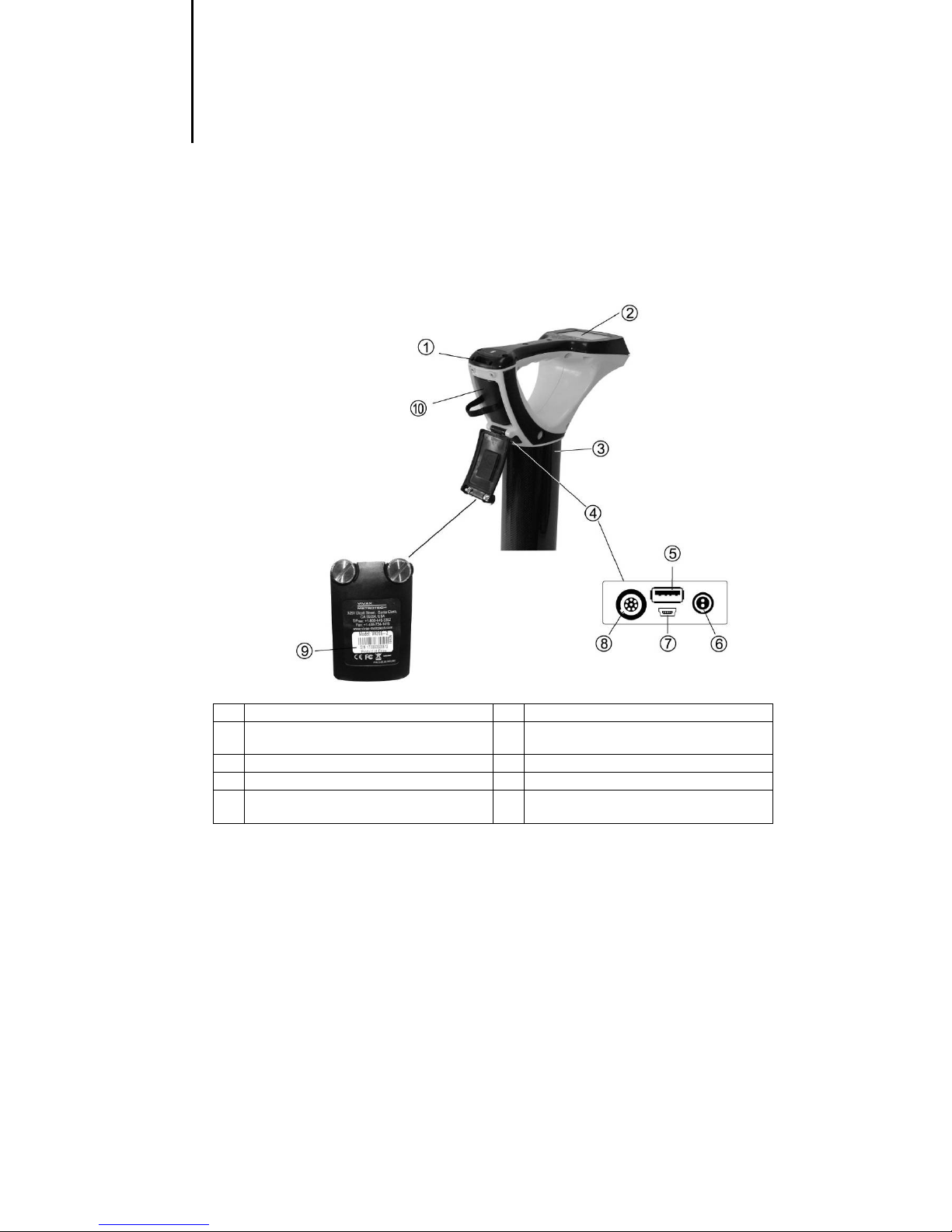
Always quote your receiver and transmitter model number, serial number and software revision number when
requesting product support. They can be found as follows: (for reference only)
1 Model & Serial Number
NOTE
The transmitter Model & Serial Number can be found at the bottom of the
transmitter and also inside the transmitter between the battery tray and the main
module of transmitter.
Software Revision Number: On both receiver and transmitter the software
revision number is displayed on the LCD during the start up sequence or can be
found in the “About” section of the user menu.

2 Service & Support
Page 5 of 72
2.2 Distributors and Service Centers Closest to You:
United State of America Europe
Vivax-Metrotech Corporation SebaKMT
3251 Olcott Street, Seba Dynatronic
Santa Clara, CA 95054, USA Mess-und Ortungstechnik GmbH
Website : www.vivax-metrotech.com Dr.-Herbert-Iann-Str. 6,
96148 Baunach, Germany
Sales & Sales Support:
T/Free : +1-800-446-3392 Tel : +49-9544-680
Tel : +1-408-734-1400 Fax : +49-9544-2273
Fax : +1-408-734-1415 Website : www.sebakmt.com
Application Support: Australasia
T/Free : +1-800-624-6210 SebaKMT AUS
Tel : +1-408-454-7159 Unit 1, 176 South Creek Road,
Fax : +1-408-743-5597 Cromer NSW 2009, Australia
Email : applications@vxmt.com
Tel : +61-2-9972-9244
Service & Repairs: Fax : +61-2-9972-9433
T/Free : +1-800-638-7682 Website : www.sebakmtaus.com
Tel : +1-408-962-9990 Email : sales@sebakmtaus.com
Fax : +1-408-734-1799 service@sebakmtaus.com
China
All Other Department: Leidi Utility Supply (Shanghai) Ltd.
T/Free : +1-877-330-1647 No. 780, Tianshan Rd,
Tel : +1-408-734-3880 Shanghai, China 200051
Fax : +1-408-962-9993
Tel : +86-21-5235-3001
Canada 4008-206-719
Vivax Canada Inc. Fax : +86-21-5235-8365
400 Esna Park Drive, Website : www.leidi.com
Ontario, L3R 3K2, Canada
Tel : +1-289-846-3010
Fax : +1-905-752-0214
Website : www.vivax-metrotech.com
3 vLocPro2 Receiver
Page 6 of 72
3. vLocPro2 Receiver
3.1 vLocPro2 Receiver
The vLocPro2 is a Precision Location System designed to meet the needs of Utility Companies and their
contractors. The following describes the features and use of the receiver:
1 Optional Bluetooth Module 6 Charging Socket
2 Pushbutton & Display 7 Mini USB Port Data Transfer and Software
Upgrade
3 Carbon Fiber Reinforced Antenna Assembly 8 Accessories Port
4 Accessory & Charging Sockets 9 Model# & Serial#
5 USB Memory Stick Data Transfer, active on
some models
10 AA Battery Pack/Rechargeable Battery Pack

3 vLocPro2 Receiver
3.2
Charging the Receiver Batteries
The vLoc series 2
can be used with either alkaline batteries or it can be supplied with an interchangeable
rechargeable battery pack.
When alkaline battery is used, Icon A will appear on the screen. When the
Icon B will be displayed.
In both cases, the number of bars illuminated within the bat
remaining.
Rechargeable batteries are supplied with a mains charger. This is specific to the batteries, avoid the use of
other manufacturers’ chargers as these may damage the battery pack and may result in overheat
battery pack.
To charge the rechargeable batteries
as charging is done in
side the receiver
Connect the charger to the charging socket of the receiver.
LED indicator on the charger will illuminate red until the batteries are fully charged at which time the LED will
change to green.
W
ARNING
Rechargeable batteries are supplied with a mains or 12V
speci
fic to the batteries. Only use the charger that is appropriate for the batteries
in the product. If in doubt
the appropriate charger could result in damage to the battery pack, locator and
in extreme c
Avoid charging the unit in extreme temperature conditions. (i.e. below 0ºC and
above 45ºC)
Although V
features always immediately discontinue use of the charger and battery
the battery pack becomes excessively warm. Return both to where they were
purchased for investigation.
Always ensure batteries have at least a partial charge if storing for long periods
without use.
Dispose of all batteries in accordance with you
Federal/State and local regulations.
Never dismantle batteries, put them in fire, or get wet.
Charging the Receiver Batteries
can be used with either alkaline batteries or it can be supplied with an interchangeable
When alkaline battery is used, Icon A will appear on the screen. When the
rechargeable battery pack is used
In both cases, the number of bars illuminated within the bat
tery icon indicates the amount of charge
Rechargeable batteries are supplied with a mains charger. This is specific to the batteries, avoid the use of
other manufacturers’ chargers as these may damage the battery pack and may result in overheat
To charge the rechargeable batteries
,
first make sure the pack is inserted in the receiver battery compartment
side the receiver
.
Connect the charger to the charging socket of the receiver.
Connect charger t
o the mains and switch on. The
LED indicator on the charger will illuminate red until the batteries are fully charged at which time the LED will
ARNING
Rechargeable batteries are supplied with a mains or 12V
DC
charger. These are
fic to the batteries. Only use the charger that is appropriate for the batteries
in the product. If in doubt
, call Vivax-Metrotech
Customer Service. Failure to use
the appropriate charger could result in damage to the battery pack, locator and
in extreme c
ases cause fire.
Avoid charging the unit in extreme temperature conditions. (i.e. below 0ºC and
above 45ºC)
Although V
ivax-Metrotech
batteries include all the required safety related
features always immediately discontinue use of the charger and battery
the battery pack becomes excessively warm. Return both to where they were
purchased for investigation.
Always ensure batteries have at least a partial charge if storing for long periods
without use.
Dispose of all batteries in accordance with you
r company procedures and
Federal/State and local regulations.
Never dismantle batteries, put them in fire, or get wet.
Icon A Icon B
Page 7 of 72
can be used with either alkaline batteries or it can be supplied with an interchangeable
rechargeable battery pack is used
,
tery icon indicates the amount of charge
Rechargeable batteries are supplied with a mains charger. This is specific to the batteries, avoid the use of
other manufacturers’ chargers as these may damage the battery pack and may result in overheat
ing of the
first make sure the pack is inserted in the receiver battery compartment
o the mains and switch on. The
LED indicator on the charger will illuminate red until the batteries are fully charged at which time the LED will
charger. These are
fic to the batteries. Only use the charger that is appropriate for the batteries
Customer Service. Failure to use
the appropriate charger could result in damage to the battery pack, locator and
Avoid charging the unit in extreme temperature conditions. (i.e. below 0ºC and
batteries include all the required safety related
features always immediately discontinue use of the charger and battery
pack if
the battery pack becomes excessively warm. Return both to where they were
Always ensure batteries have at least a partial charge if storing for long periods
r company procedures and

3 vLocPro2 Receiver
Page 8 of 72
3.3 vLocPro2 Receiver Main Display
The vLocPro2 has several display options – the display shown below is representative of the types of display
and icons used.
1 Digital Display of Signal Response 10 Frequency Select
2 Loudspeaker Status 11 Gain Control (reduce gain)
3 Bluetooth and GPS Signal Quality 12 On/Off Control
4 Alkaline/Rechargeable Battery Status 13 Compass Line Direction Indicator
5 Peak Signal Indication 14 Left vs Right Indication
6 Frequency 15 db Gain Setting
7 Location Mode Select 16 Analogue Display of Signal Response
8 Gain Control (increase gain) 17 Continuous Depth/Current
9 Information Depth/Current Measurement 18 Location Mode
(Peak, Null, Sonde, Broad, Peak Arrows)
Note: Bluetooth function is available in vLoc receivers with Bluetooth module only.
3 vLocPro2 Receiver
Page 9 of 72
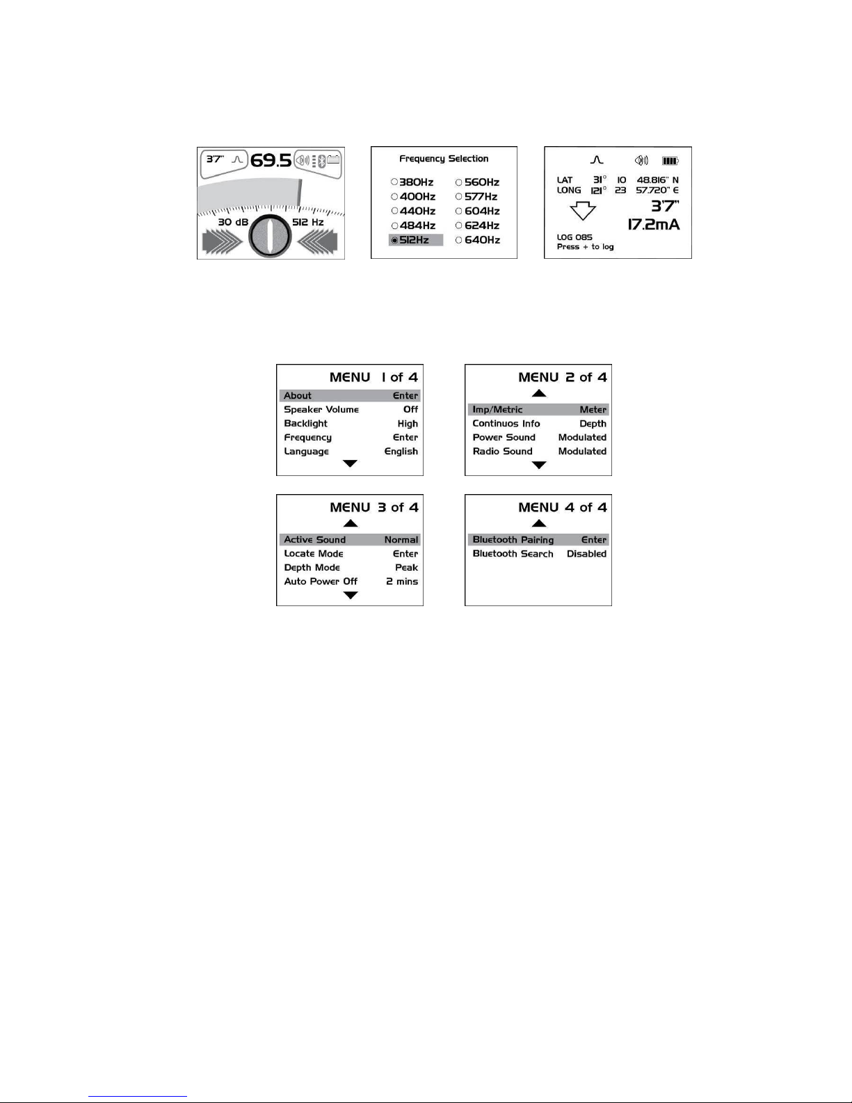
3.4 vLocPro2 Receiver Screen Shots
vLocPro2 Receiver Menus (Actual menu may differ)
Main Display
Setup Menu – Frequencies
Depth & Current Measurement
Frequencies selected here are the
only ones displayed in the
frequency box on the Main
Display
Main Menu
The vLocPro2 is a Precision Location System designed to meet the needs of Utility Companies and their
contractors. The following describes the features and use of the receiver.
3 vLocPro2 Receiver
Page 10 of 72
3.5 Locating Mode (Response)
The vLocPro2 receiver has four antennas, and these can be toggled through different configurations (modes)
to provide different responses to the signals radiating from the buried pipes and cables. The modes are:
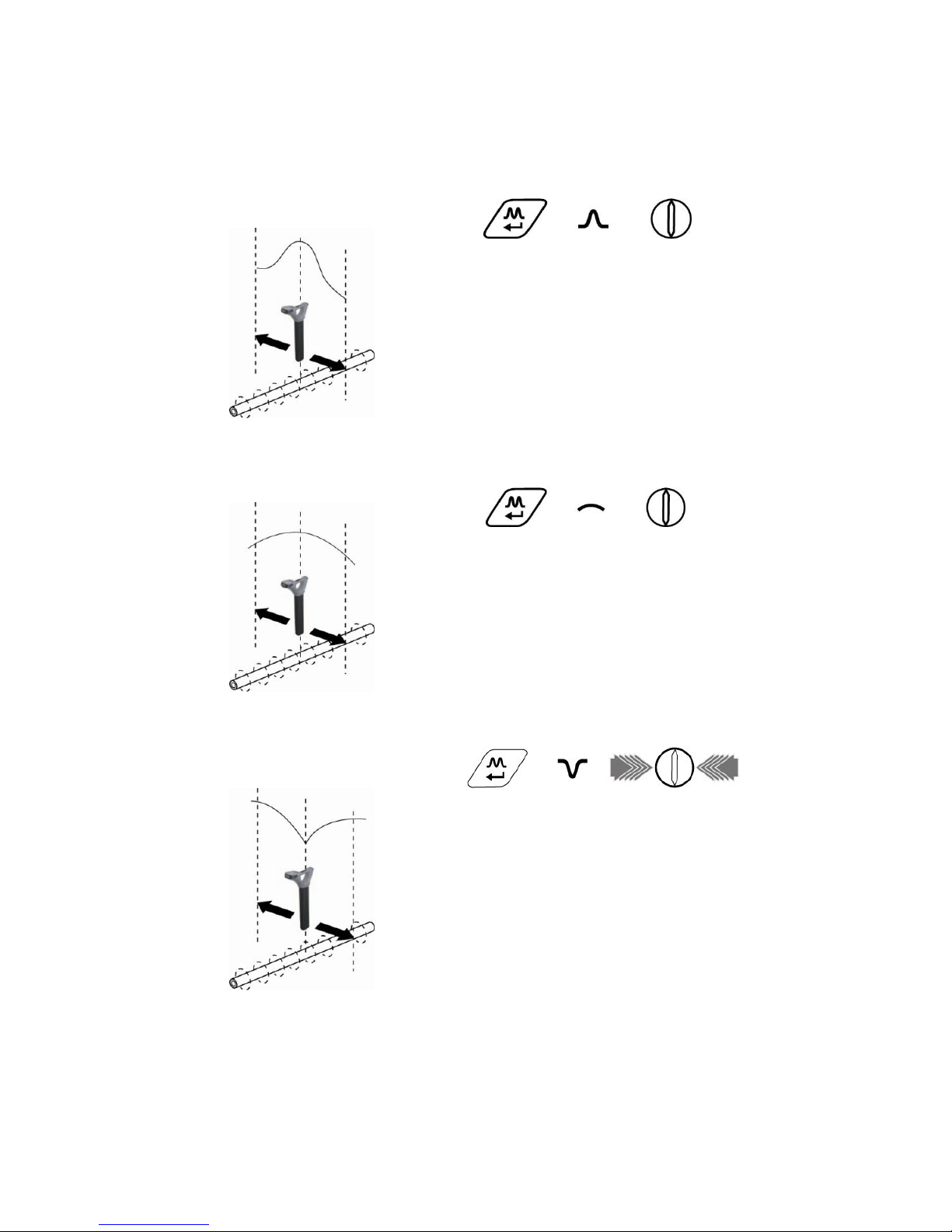
3.5.1 Peak Response Mode
This uses the two horizontal antennas and provides a “Peak” or maximum
signal response over the center of the radiated signal from the buried line.
The compass line direction indicator shows the direction of the cable
(available in Active modes). The color of the compass changed from clear
to blue when the receiver is in line with the buried line.
This is the most accurate of the locating modes as both antennas are
used to provide a clearly identifiable “Peak”. In the “Peak” mode, a “Peak”
signal indicator helps to clarify the position of the “Peak”. This shows the
last “Peak” located for a few seconds, enabling the user to return to that
position quickly.
3.5.2 Broad Peak Mode
This uses a single horizontal antenna and provides a “Peak” or maximum
signal response over the center of the radiated signal from the buried line.
The compass line direction indicator shows the direction of the cable
(available in Active modes). The color of the compass changed from clear
to blue when the receiver is in line with the buried line.
This is less accurate than the twin horizontal antenna “Peak” mode – but
is useful if the buried line is particularly deep. For pinpointing the line, the
“Peak” mode should be used.
3.5.3 Null Mode
This uses vertical antennas and provides a minimum or “Null” response
over the center of the radiated signal from the buried line. The compass
line direction indicator shows the direction of the cable (available in Active
modes). The color of the compass changed from clear to blue when the
receiver is in line with the buried line.
Some users prefer the null response; it works well in uncongested areas,
but is more prone to inaccuracies due to distortion of the radiated signal
in congested areas.
Left/right indication arrows are also displayed when in “Null” mode. The
arrows indicate the direction to move the receiver to locate the position of
the buried line.
Pushbutton
Icon
Compass Line
Direction Indicator
Pushbutton
Icon
Compass Line
Direction Indicator
Pushbutton
Icon
Compass Line
Direction Indicator

3 vLocPro2 Receiver
Page 11 of 72
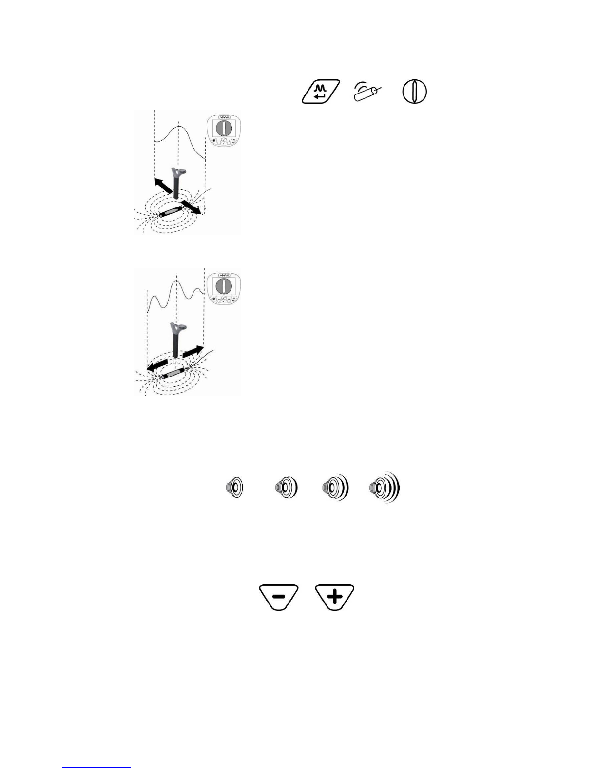
3.5.4 Peak with Arrows Response Mode
This uses the two horizontal antennas and provides a “Peak” or maximum
signal response over the center of the radiated signal from the buried line.
The compass line direction indicator shows the direction of the cable
(available in Active modes). The color of the compass changed from clear
to blue when the receiver is in line with the buried line.
This is the most accurate of the locating modes as both antennas are
used to provide a clearly identifiable “Peak”. In the “Peak” mode, a “Peak”
signal indicator helps to clarify the position of the “Peak”. This shows the
last “Peak” located for a few seconds, enabling the user to return to that
position quickly.
Left/Right arrows also guide the user to the line. However, it should be
noted that the arrows use the Null antenna to resolve which arrows are
activated. The null antenna is not as accurate in distorted fields as the
peak antennas. Therefore, when pinpointing, use the peak bargraph to
determine the position of the line.
Note
If the arrows indicated a different position for the cable than the peak
bargraph position, this indicates the possibility of a distorted field. Check
by taking a depth reading on the ground and then lift the cable locator a
known distance such as 0.5m (3ft). If the depth does not increase by this
amount it confirms a distorted field and the data should be treated with
caution.
Pushbutton
Icon
Compass Line
Direction Indicator
3 vLocPro2 Receiver
Page 12 of 72
3.5.5 Sonde Mode
Sonde mode uses the antennas in a “Peak” configuration. An ICON on
the display indicates if the receiver is in Sonde mode.
A Sonde is a small transmitting coil that is powered by its own internal
battery, or by an external transmitter.
Due to its construction, a Sonde gives a different “Peak” pattern – when
locating along the direction of the Sonde – instead of the usual single
“Peak”, the Sonde provides three distinct peaks – a small “Peak” – a
large “Peak” – a small “Peak”. The Sonde is located under the center of
the large “Peak” when located across the direction of the Sonde and it
gives the conventional peak response. Note that the Compass Line
Indicator points across the line of the Sonde when directly over it and the
color of the compass change from clear to blue.
The vLocPro2 receiver must be used in a different orientation when
locating a Sonde – due to the way the signal from the Sonde radiates.
With the front of the receiver pointing across suspected direction of the
Sonde – pinpoint forward and backward (across the Sonde) and then
move along the line of the Sonde until the maximum peak is located (in
other words rotate the receiver 90 degrees from the orientation normally
used when locating pipes and cables).
A Sonde is typically used for locating non metallic pipes or ducts, and the
camera end of a sewer inspection camera. Low frequency versions (512
Hz/640 Hz) can transmit through some metallic pipes such as cast iron
pipes – which are why they are frequently used with sewer inspection
cameras.
For using the compass feature to locate Sondes, please refer to 9.1.3.
3.6 Audio
The visual display is also accompanied by an audio response. The output level (volume) of this response is
set by entering the “Setup Menu”. Press and hold “i” pushbutton for 2 seconds to enter setup menu. The
setup display defaults to volume. Use the “M” pushbutton to toggle through the available options (Off – Low –
Med – High). Press the “i” pushbutton again to exit the setup menu. As the loudspeaker uses a significant
amount of power, using lower volume can make the battery life of the receiver last longer.
3.7 Sensitivity Control
In manual modes, “+” and “-” pushbuttons are provided to increase or reduce the sensitivity of the receiver. If
the bar graph moves towards the minimum or maximum a single touch of the opposite pushbutton returns it
to approximately 50% deflection. Holding down or repeated pushing of the “+” or “-” pushbuttons
increments/decrements the gain.
Pushbutton
Icon
Compass Line
Direction Indicator
Pushbutton Pushbutton

3 vLocPro2 Receiver
Page 13 of 72
3.8 Frequency Selection
The vLocPro2 receiver is capable of locating a large number of frequencies or frequency combinations. A list
of these frequencies can be accessed using the setup menu. Most of these frequencies listed – you will
never use – the setup menu allows you to select the frequencies you wish to use regularly. The frequency
select pushbutton on the main receiver pad is used to toggle through the frequencies defined using the setup
menu. The operating frequency will be shown at the lower right side of the display. You can change this
selection at any time using the setup menu.
The initial frequencies set at the time the unit is supplied are “Power”, “Radio” and the frequencies used by
the transmitter purchased. See the transmitter section for suggestions of which frequency is best suited to
specific applications.
To select the frequencies you wish to use regularly – enter the setup menu
by pressing and holding the “i” pushbutton for 2 seconds. Use the “+” and
“-” to select the word “Frequency” – then press the “M” pushbutton to
display the list of available frequencies.
The “+” and “-” pushbuttons are used to navigate the list of frequencies. To
add a frequency to the “Frequently used list” press the “M” pushbutton and
a dot will appear in the circle alongside the frequency. To deselect a
frequency press the “M” pushbutton and the dot will disappear. Once your selection is completed press “i”
pushbutton once to return to the setup menu, and again to exit the setup menu.
Pushbutton
3 vLocPro2 Receiver
Page 14 of 72
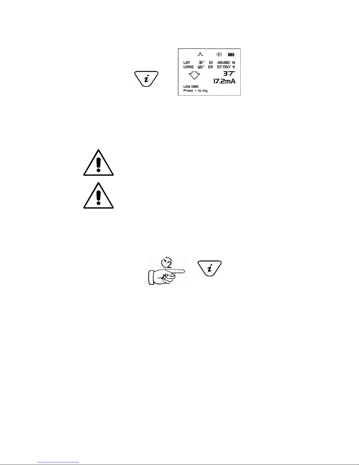
3.9 Information Pushbutton (Depth & Current)
Pressing the “i” (information) pushbutton will display the depth to the center of the radiated signal and a
measurement of the current (press the pushbutton briefly – remember if you press and hold – you enter the
setup menu. If you do enter the setup menu – press the “i” pushbutton again to return to the locating screen –
then try again).
The display shown above shows Long/Lat positional informaiton. This is only displayed when the equipment
is paired with a valid GPS system.
IMPORTANT
When locating a cable or pipe (“Line”) – the instrument should be in “Peak”
mode and the depth and current measurements should only be taken with the
bottom of the receiver standing on the ground and directly in line with the
target line.
IMPORTANT
When locating a Sonde – set the mode to Sonde - then the instrument will
automatically be in “Peak” configuration. Depth measurements should only be
taken with the bottom of the receiver standing on the ground and at ninety
degrees to the Sonde.
The accuracy of depth and current readings depends on the quality of the radiated signal being located. If the
signal is symmetrical, the depth reading will be accurate to within 5% of the actual depth. If the signal is
distorted, depth readings will be less accurate. When taking depth measurement, always hold the receiver at
900to the ground.
3.10 Information Pushbutton (Setup Menu)
As described previously, a second function performed by the “i” is to access the SETUP menu. Press and
hold the “i” pushbutton for two seconds to display the SETUP menu. Use the “+”, “-” to navigate through the
various options and use the “M” pushbutton to select. To exit the setup menu, press the “i” pushbutton.
The setup menu allows the user to configure their personal preference, this menu can be accessed and
changed at any time.
Pushbutton
Pushbutton
Other manuals for vLocPro2
1
This manual suits for next models
1
Table of contents
Other Vivax Metrotech Camera Accessories manuals


