Vivid CLV-411 User manual

CLV-411 CAMERA LINK VIDEO SPLITTER
User’s Manual
Document # 200587, Rev 1.0, 5/1/2009
Vivid Engineering
418 Boston Turnpike #104 • Shrewsbury, MA 01545
Phone 508.842.0165 • Fax 508.842.8930

Table of Contents
1. Introduction 1
1.1. Overview 1
1.2. Features 3
1.3. Functional Description 4
1.3.1. Master Frame Grabber Selection 6
1.4. Typical Applications 7
1.4.1. Standard Base Application 7
1.4.2. Medium Application 8
1.5. Specifications 9
2. Interface 10
2.1. Front Panel Connections 10
2.2. Rear Panel Connections 11
2.2.1. Master Select Connector 12
2.3. Camera Connector Signals 13
2.3.1. Cable Shield Grounding 13
3. Mechanical 15
3.1. Dimensions 15
3.2. External Power Supply 16
4. Regulatory Compliance 17
4.1. FCC Compliance Statement 17
4.2. Canadian Compliance Statement 17
5. Revision History 18

1
1. Introduction
1.1. Overview
The CLV-411 Camera LinkTM1Video Splitter interfaces one Camera Link camera to up-to
four frame grabbers using standard Camera Link cables. This enables the use of multiple
frame grabbers for applications requiring parallel or distributed processing, camera
sharing, etc. One frame grabber acts as master and provides control and communications
to the camera. The remaining frame grabbers receive camera video data only. The master
frame grabber is selectable and may be dynamically changed for applications requiring
camera control sharing.
The CLV-411 incorporates high-speed 85 MHz interfaces and supports the Camera Link
base configuration. Medium configuration applications are supported using two CLV-
411s. Multiple CLV-411s may be cascaded for large parallel processing systems.
The CLV-411 Camera Link Video Splitter is housed in a sturdy, compact aluminum
enclosure.
1The Camera LinkTM interface standard enables the interoperability of cameras and frame grabbers,
regardless of vendor. The Automated Imaging Association (AIA) sponsors the Camera LinkTM
program including the oversight Camera Link Committee, the self-certification program, and the
product registry. The Camera LinkTM specification may be downloaded from the AIA website,
found at www.machinevisiononline.org
Camera LinkTM is a trademark of the Automated Imaging Association

2
Camera Link Video
Splitter CLV-411
V
ivid
E
ngineering
FRAME GRABBER 3
FRAME GRABBER 1 FRAME GRABBER 2
FRAME GRABBER 4

3
1.2. Features
•Interfaces one camera to up-to four frame grabbers
•Supports parallel or distributed processing, camera sharing, etc
•Uses standard Camera Link cables (not included)
•Supports Camera Link Base configuration
•Medium configuration support using two CLV-411s
•May be cascaded for large parallel processing systems
•High-speed 85 MHz interface chipset
•Dynamic master frame grabber selection via opto-isolated control inputs
•Front panel LEDs identify master frame grabber
•Flow-through connector positioning
•Sturdy, compact aluminum enclosure w/ mounting flange
•Universal power supply included
•3-year warrantee

4
1.3. Functional Description
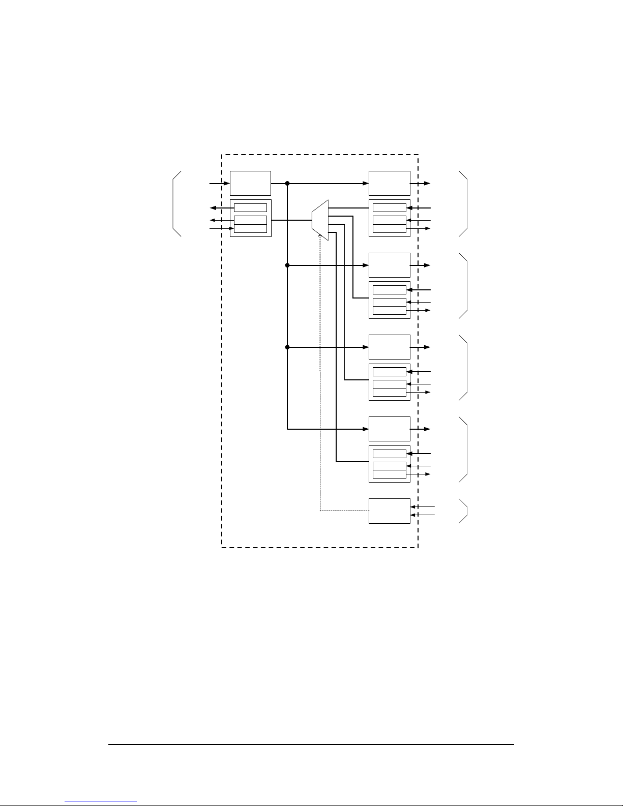
A block diagram of the CLV-411 is provided in Figure 1-1. The CLV-411 interfaces one
camera to up-to four frame grabbers using standard Camera Link cables.
One frame grabber acts as the master (primary). The master frame grabber receives video
data from the camera, and can also control and communicate with the camera. The
interface between the camera and the master frame grabber utilizes the entire Camera Link
signal set defined in the Camera Link Specification for “base” configurations. This
consists of video data, camera control, and serial communications.
The remaining frame grabbers act as slaves (secondary). The interface between the
camera and the slave frame grabbers utilizes video data only. The slave frame grabbers
receive video data, but cannot control or communicate with the camera.
Some applications require the ability to share control of the camera between the frame
grabbers (i.e. share the master role). CLV-411 allows any of the four frame grabbers to
act as the master. Selection of the master frame grabber is made via the opto-isolated
master select inputs. When the select inputs change, the master frame grabber is
immediately reassigned accordingly. This enables dynamic (i.e. real-time) selection of the
master frame grabber for applications requiring this capability.
Frame grabber 1 is the default master frame grabber whenever the opt-isolated inputs are
not being used. Front panel LED indicators identify the current master frame grabber.
Since the CLV-411 regenerates all signals, it also acts as a repeater and supports an
additional 10 meters of separation between camera and frame grabbers.
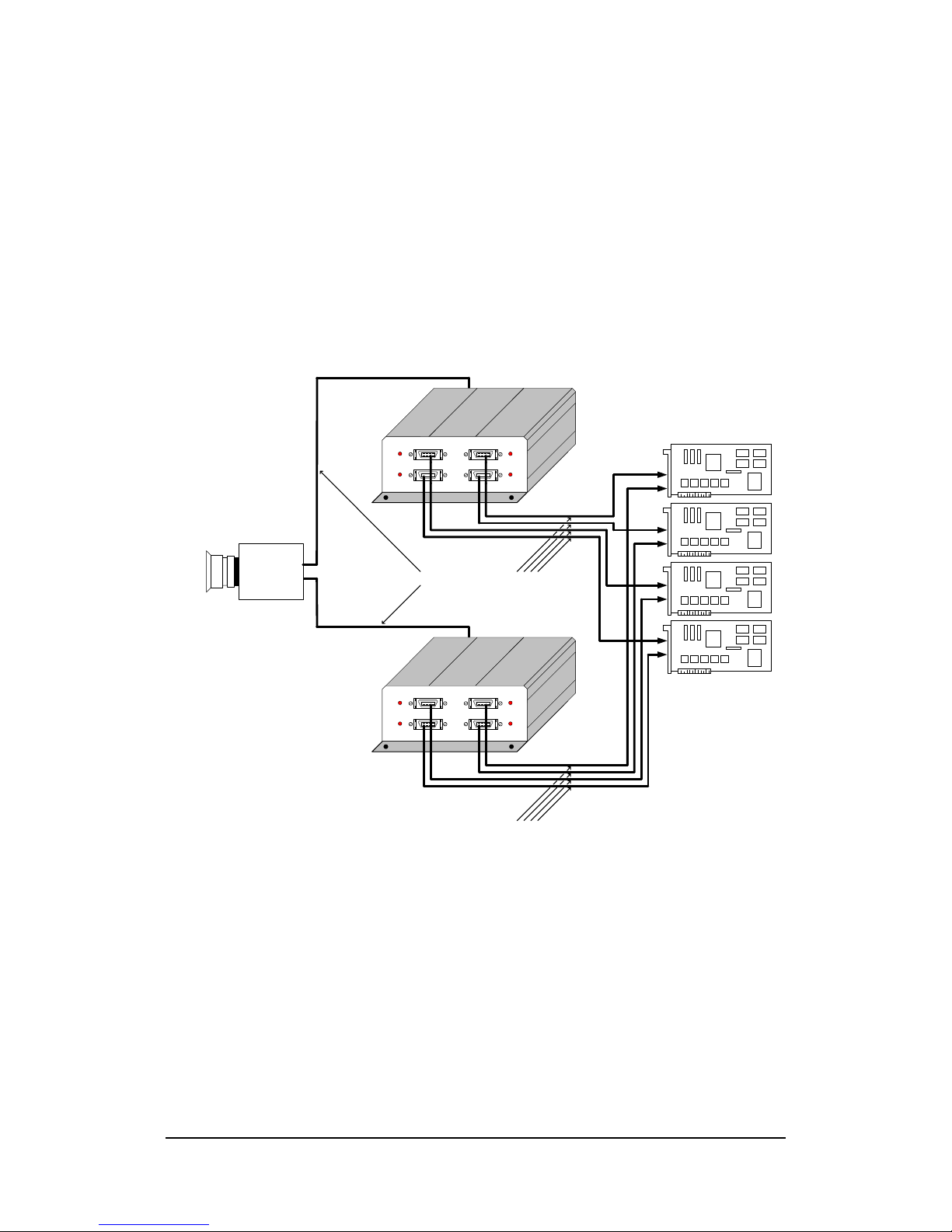
The CLV-411 is also compatible with the second Camera Link cable used in the
“medium” configuration, enabling a pair of CLV-411s to be used in parallel to support
medium configuration applications.
The CLV-411 is powered by an external wall plug-in power supply.

5
CLV-411 Camera Link Video Splitter
Mux LVDS Rcvr
Video
Data
Camera
Control
Serial
Comm
LVDS Xmtr
Channel Link
Transmitter
LVDS Rcvr
LVDS Rcvr
Video
Data
Camera
Control
Serial
Comm
LVDS Xmtr
Channel Link
Transmitter
LVDS Rcvr
LVDS Rcvr
Video
Data
Camera
Control
Serial
Comm
LVDS Xmtr
Channel Link
Transmitter
LVDS Rcvr
LVDS Rcvr
Video
Data
Camera
Control
Serial
Comm
LVDS Xmtr
Channel Link
Transmitter
LVDS Rcvr
Video
Data
Camera
Control
Serial
Comm
LVDS Xmtr
LVDS Rcvr
Channel Link
Receiver
LVDS Xmtr
To Camera Link
Camera
To Camera Link
Frame Grabber 1
To Camera Link
Frame Grabber 2
To Camera Link
Frame Grabber 3
To Camera Link
Frame Grabber 4
DB-9
Connector
Opto-
Isolators
Master
Select
Figure 1-1: CLV-411 Block Diagram

6
1.3.1. Master Frame Grabber Selection
Master frame grabber selection is supported via the master select port. Note that the
use of this port is optional.
Two opto-isolated control inputs are provided via a DB9 connector on the rear panel.
Voltage levels applied to these inputs select the master frame grabber. Master
reassignment occurs instantaneously, enabling real-time master selection. When no
connection is made to the DB9, Frame Grabber 1 is master (default). See Section
2.2.1 for connector pin assignments and signal characteristics.
The front-panel indicator LEDs identify the current master frame grabber.
Table 1-1: Master Frame Grabber Select Inputs
SEL1
SEL0
Master Frame Grabber
0 0 Frame Grabber 1
0 1 Frame Grabber 2
1 0 Frame Grabber 3
1 1 Frame Grabber 4
No Connection Frame Grabber 1

7
1.4. Typical Applications
1.4.1. Standard Base Application
A typical CLV-411 base application is shown in Figure 1-2. A Camera Link base
configuration camera is connected to a single CLV-411 via a standard Camera Link
cable. Additional Camera Link cables are then used to connect the CLV-411 to up-to
four Camera Link frame grabbers.
Since the master select port is not being used in this example, frame grabber 1 is the
default master. The master frame grabber provides camera control and
communication, as well as performing processing functions. The slave frame
grabbers cannot control or communicate with the camera, but are used for parallel or
distributed processing, monitoring, etc.
Camera Link Video
Splitter CLV-411
Vivid Engineering
FRAME GRABBER 3
FRAME GRABBER 1 FRAME GRABBER 2
FRAME GRABBER 4
Camera Link
Camera Standard Camera Link Cables
Camera Link
Frame Grabbers
Figure 1-2: CLV-411 Standard Application (Base)

8
1.4.2. Medium Application
A CLV-411 medium application is shown in Figure 1-3. Medium configurations, in
which two cables connect the camera to the frame grabbers, are supported using two
CLV-411s in parallel. A Camera Link medium configuration camera is connected to
two CLV-411s via a pair of standard Camera Link cables. Additional Camera Link
cables are then used to connect the CLV-411s to the Camera Link frame grabbers.
Camera Link Video
Splitter CLV-411
V
ivid
E
ngineering
FRAME GRABBER 3
FRAME GRABBER 1 FRAME GRABBER 2
FRAME GRABBER 4
Camera Link
Camera
Standard Camera Link Cables
Camera Link
Frame Grabbers
Camera Link Video
Splitter CLV-411
V
ivid
E
ngineering
FRAME GRABBER 3
FRAME GRABBER 1 FRAME GRABBER 2
FRAME GRABBER 4
Standard Camera Link Cables
Figure 1-3: CLV-411 “Medium” Application

9
1.5. Specifications
Table 1-1: CLV-411 Specifications
Feature
Specification
Video Interfaces Camera Link “base” configuration
Video Connectors 26-pin MDR type
Camera Frequency 20-85 MHz
Chipset National Semi. DS90CR287 / DS90CR288A
Select Connector Female 9-pin D-Sub (DB9), opto-isolated inputs
Power Supply Universal wall style w/ US & Europe outlet plugs
Power Jack 2.1 x 5.5 mm, center-positive
Power Requirements 5-7 VDC, 380 mA (typical)
Cabinet Dimensions 5.28” (L) x 2.08” (H) 6.12” (D)
Weight 20 oz
Operating Temperature Range 0 to 50° C
Storage Temperature Range -25 to 75° C
Relative Humidity 0 to 90%, non-condensing
Compliance FCC Class A, ROHS, (CE EN55024 pending)

10
2. Interface
2.1. Front Panel Connections
The CLV-411 Camera Link Video Splitter front panel is shown in Figure 2-1. The front
panel contains four video connectors for connecting to the frame grabbers. The four LEDs
identify which frame grabber is “master” as discussed in prior sections.
The video connectors are 3M MDR-26 types as specified in the Camera Link Spec.
Figure 2-2 identifies the MDR-26 pin positions.
Camera Link Video
Splitter CLV-411
V
ivid
E
ngineering
FRAME GRABBER 3
FRAME GRABBER 1 FRAME GRABBER 2
FRAME GRABBER 4
Figure 2-1: CLV-411 Front Panel
pin 1pin 13
pin 14pin 26
Figure 2-2: MDR-26 Connector Pin Positions

11
2.2. Rear Panel Connections
The CLV-411 Camera Link Video Splitter rear panel is shown in Figure 2-3. The rear
panel contains a 26-pin MDR video connector for connecting to the camera, the master
select connector, and a DC power jack.
The MDR-26 connector is a 3M device as specified in the Camera Link Spec.
The master select connector is a standard 9-pin female D-Sub type (DB9). Figure 2-4
identifies the DB9 pin positions.
DC power jack accepts 5-7 volts DC. Polarity is center-positive.
CAMERA 5-7 VDC
SELECT
Figure 2-3: CLV-411 Rear Panel
pin 5 pin 1
pin 9 pin 6
Figure 2-4: Female DB9 Connector Positions

12
2.2.1. Master Select Connector
A standard female DB9 connector is located on the rear panel for master frame
grabber selection. Use of this connector is optional. The CLV-411 will default to
frame grabber 1 as master when no connection is made. Table 2-1 identifies the DB9
signal assignments.
Table 2-1: Master Select DB9 Connector
Signal Name
DB9 Pin# Notes
SEL0 + 1 Master Select 0
n/c 2
no connection
n/c 3
no connection
SEL1 + 4 Master Select 1
n/c 5
no connection
SEL0 - 6 Master Select 0 Return
n/c 7
no connection
n/c 8
no connection
SEL1 - 9 Master Select 1 Return
Two control inputs (SEL0+/- & SEL1+/-) are used to select the master frame grabber.
The control inputs are received by opto-isolator devices for system electrical isolation.
SEL0 is logic “1” when 5-10 VDC is applied between SEL0+ and SEL0-. SEL0 is
logic “0” when 0 VDC is applied. Similarly, SEL1 is logic “1” when 5-10 VDC is
applied between SEL1+ and SEL1-. SEL1 is logic “0” when 0 VDC is applied.

13
2.3. Camera Connector Signals
The MDR-26 video connector signal assignments comply with the Camera Link “base”
configuration. The camera connector signal assignments correspond to the frame grabber
interface defined in the Camera Link Specification. Conversely, the frame grabber
connector assignments are as defined for the camera interface in the Camera Link
Specification. This arrangement provides compatibility with standard Camera Link
cables.
Table 2-2 identifies the signal assignments for the MDR-26 video connectors.
2.3.1. Cable Shield Grounding
Camera and frame grabber cable “outer” shields are connected to the CLV-411
aluminum case. The case is isolated from the CLV-411 circuitry and the cable
“inner” shields.
The frame grabber cable “inner” shield connects to circuit digital ground, maintaining
signal reference levels between the CLV-411 and the frame grabber.

14
Table 2-2: MDR-26 Connector Assignments
Camera Link Signal
Name
Camera
Connector
Pin #
(frame grabber
pinout)
Frame Grabber
Connectors
Pin #
(camera pinout)
Signal Direction
Inner shield 1 1 N/A
Inner shield 14 14 N/A
X0- 25 2 CAM →FG
X0+ 12 15 CAM →FG
X1- 24 3 CAM →FG
X1+ 11 16 CAM →FG
X2- 23 4 CAM →FG
X2+ 10 17 CAM →FG
Xclk- 22 5 CAM →FG
Xclk+ 9 18 CAM →FG
X3- 21 6 CAM →FG
X3+ 8 19 CAM →FG
SerTC+ 20 7 FG →CAM
SerTC- 7 20 FG →CAM
SerTFG- 19 8 CAM →FG
SerTFG+ 6 21 CAM →FG
CC1- 18 9 FG →CAM
CC1+ 5 22 FG →CAM
CC2+ 17 10 FG →CAM
CC2- 4 23 FG →CAM
CC3- 16 11 FG →CAM
CC3+ 3 24 FG →CAM
CC4+ 15 12 FG →CAM
CC4- 2 25 FG →CAM
Inner shield 13 13 N/A
Inner shield 26 26 N/A
“FG” = Frame Grabber, “CAM” = Camera

15
3. Mechanical
3.1. Dimensions
The CLV-411 Camera Link Video splitter cabinet dimensions are shown in Figure 3-1.
The CLV-411 is housed in a sturdy aluminum enclosure. The body is extruded aluminum,
with detachable front and rear endplates. The enclosure incorporates a mounting flange.
The flange contains four predrilled holes (0.15” diameter) for convenient equipment
mounting. A mounting drawing is provided in Figure 3-2.
5.28"
2.08
6.12" (including mountingflanges)
Camera Link Video
Splitter CLV-411
V
ivid
E
ngineering
FRAME GRABBER 3
FRAME GRABBER 1 FRAME GRABBER 2
FRAME GRABBER 4
Figure 3-1: CLV-411 Cabinet Dimensions

16
6.12"
5.28"
(Front )
(Rear)
4.76"
5.62"
Mounting Holes (4): 0.15" dia
Figure 3-2: Mounting Template
3.2. External Power Supply
The CLV-411 is powered by 5-7 VDC and incorporates a standard 2.1 x 5.5 mm DC
power jack. Power plug polarity is center-positive.
The multi-nation wall-mount power supply (included) handles a wide power range (90-
264 VAC, 47-63 Hz) and comes with a set of outlet plugs suitable for most countries (US,
Europe, UK, etc).
The CLV-411 is protected by an internal resettable fuse.

17
4. Regulatory Compliance
4.1. FCC Compliance Statement
This equipment has been tested and found to comply with the limits for a Class A digital
device, pursuant to Part 15 of the FCC Rules. These limits are designed to provide a
reasonable protection against harmful interference when the equipment is operated in a
commercial environment. Operation of this equipment in a residential area is likely to
cause harmful interference in which case the user will be required to correct the
interference at his/her own expense.
Changes or modifications not expressly approved by the party responsible for compliance
could void the user’s authority to operate the equipment.
4.2. Canadian Compliance Statement
This digital apparatus does not exceed the Class A limits for radio noise emissions from
digital apparatus set out in the Radio Interference Regulations of the Canadian Department
of Communications.

18
5. Revision History
Table 5-1: CLV-411 User’s Manual Revision History
Document ID #
Date Changes
200587-1.0 5/1/09 Initial release of manual
Table of contents