Vivid CLT-371A User manual

CLT-371A CAMERA LIN K T R ANSLATOR
User’s Manual
Document # 201488, Rev 0.1, 8/31/2023 (preliminary)
©Vivid Engineering
415 Boston Turnpike, Suite 305 • Shrewsbury, MA 01545
Phone 508.842.0165 • Fax 508.842.8930
www.vividengineering.com • info@vividengineering.com

Table of Contents
1. Introduction 1
1.1. Description 1
1.2. Features 2
1.3. Block Diagram 3
1.4. Limitations 4
2. Operation 5
2.1. Camera Connection 5
2.1.1. PoCL Camera Support 5
2.2. HD-SDI Connection 6
2.2.1. HDMI / DVI-D Output Support 6
2.3. Configuration Switches 6
2.3.1. PIXEL_DEPTH 9
2.3.2. DVAL_ENABLE 9
2.3.3. COLOR 9
2.3.4. BAYER_PATTERN 9
2.3.5. WHITE_BALANCE_ENABLE 10
2.3.6. WHITE_BALANCE_WRITE_ENB 10
2.3.7. WHITE_BALANCE_SELECT 10
2.3.8. WHITE_BALANCE_TRIGGER 11
2.3.9. FORMAT 11
2.3.10. FRAME_RATE 11
2.3.11. CENTER_DISABLE 11
2.3.12. TEST_PATTERN 11

2.3.13. SYNC_SHAPE 13
2.3.14. SYNC_INVERT 13
2.3.15. SYNC_ON_CC1 14
3. Examples 15
3.1. Stand-Alone Application 15
3.2. Camera Control Application 16
3.3. Video Splitter Application 17
3.4. Configuration Example 18
4. Specifications 20
5. Interface 21
5.1. Front Panel Connections 21
5.2. Rear Panel Connections 23
6. Mechanical 23
6.1. Dimensions 24
6.2. External Power Supply 25
7. Revision History 25

1
1. Introduction
1.1. Description
The CLT-371A Camera Link Translator converts Camera Link to HD-SDI, enablingthe
use of Camera Link cameras with HD-SDI monitors and other equipment. The CLT-
371A works with most color and monochrome base-configuration cameras. HD-SDI
output is either 1920x1080 or 1280x720.
Features include automatic frame rate adaptation, Bayer white balance correction, camera
synchronization support, and an RS-232 port for camera set-up and control. USB camera
set-up and control is supported via an adapter.
No software or preprogrammingis required. Configuration is via rear-panel switch
settings.
PoCL cameras and HDMI / DVI-D output are supported using external adapters.
CLT-371A front-panel indicators identify when the unit is powered, when anactive
camera is connected, and when the camera is synchronized to the HD-SDI video output.
The CLT-371A is housed ina sturdy aluminum enclosure. A locking-plug power supply is
optional.
CAMERA
PWR
CAM
SYNC
HD-SDI BAL
SYNC OUT
Vivid Engineering
Camera Link Translator CLT-371A

2
1.2. Features
•Enables use of Camera Link cameras with HD-SDI monitors and equipment
- HDMI & DVI-D output via an external converter
•Works with most Camera Link color and monochrome base-configuration
cameras
- PoCL cameras supported using Vivid CLR-102 adapter
•HD-SDI 1920x1080@ 29.97p or30p, 1280x720 @59.94p or 60p
•Automatic frame rate adaptation; no camerasynchronization required
•Bayer white balance correction
•Crop and center for images larger/smaller than 1920x1080 or 1280x720
•RS-232 port for camera set-up and control (or USB with external adapter)
•Configured via rear-panel switches, no software or programming required
•Camera synchronization support
•Test pattern generator
•Camera presence and synchronization indicators
•Multi-nation power supply included, locking-plug version optional
•Sturdy aluminum enclosure w/ mounting flange
•3-year warrantee

3
1.3. Block Diagram
RS-232
Port
HD-SDI
Out
Video
Data
Camera Link In
CLT-371A Camera Link Translator
SMPTE
292M
Serializer
& Cable
Driver
Video Processing
- Camera video detect and measure
- Crop & center
- Frame rate adaptation
- Bayer color reconstruction
- SMPTE 274M / 296M encoding
- Synchronization trigger generation
- Camera synchronization detect
- Test patern generator
Status
Indicators
Camera
Mode
Switch #1
Camera Link
Interface
Camera
Control
(Sync)
Serial
Comm
White
Balance
Switch
HD-SDI
Mode
Switch #2
Serial
Comm
Sync
Image
Buffers
Image
Buffers
Frame
Buffers
Sync
&
Reset
Reset

4
1.4. Limitations
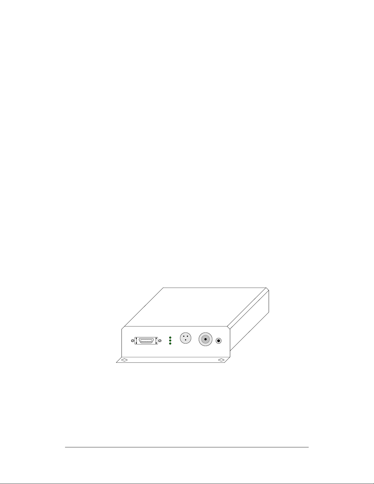
The CLT-371A is a “standard product” converter from Camera Link to HD-SDI and
works with most base-configuration cameras. However, Camera Link cameras vary
widely. Thefollowing is alist of requirements and limitations when using the CLT-371A:
Minimum Image Size:
The camera image must be at least 128 pixels per line, and 4 lines per frame (128x4).
Dual-Tap Limitation:
The CLT-371A only supports dual-tap images with “interleaved” format. This is the most
common dual-tap format inwhich two adjacent pixels from the same video line are
transmitted at a time. No other dual tap formats are supported.
Small Image Limitation:
Images smaller than the selected HD-SDI image size (1920x1080 or 1280x720) will be
cropped to multiples of 128 pixels per line. Therefore when camera “X” dimension is >=
128 pixels but less than the HD-SDI (1920 or 1280), the camera image will becropped on
the right side as necessary to reduce image “X” size to
128/256/384/512/640/768/896/1024/1152… pixels. Similarly, images smaller than the
selected HD-SDI image size will be cropped to multiples of 4 lines per frame. Therefore
when camera image “Y” dimension is >= 4 pixels but less than HD-SDI (1080 or 720), the
camera image will be cropped at the bottom as necessary to reduce image “Y” size to
4/8/12… pixels.
Large Image Limitation:
Camera images larger than 16K in the “X” dimension and/or 16K in the “Y” dimension
are not supported.
Minimum Frame Rate Requirement:
Cameras with continuous frame rates less than 2 Hz are not supported.
Active Video Requirement:
The CLT-371A measures camera video (i.e. x/y dimensions) upon connection in order to
determine processing requirements. A camera should be active (i.e. outputting video
frames) when connected to the CLT-371A. Once measured and the front panel “CAM”
light is green, camera frames may be suspended for purposes such as external triggering.
The CLT-371A must be power cycled or the reset input asserted when camera settings
affecting output image size are changed while the camera is already active.
No Zoom:
The CLT-371A does not perform zoom in or zoom out. Images larger/smaller than
1920x1080 or 1280x720 are handled using crop and center only.

5
2. Operation
2.1. Camera Connection
The CLT-371A is designed to work with most Camera Link base configuration cameras.
A “base” configuration camera can be identified by the existence of only one Camera Link
connector.
The CLT-371A incorporates the standard Camera Link “MDR” (i.e. full size). A standard
Camera Link cable is used to connect the camera tothe CLT-371A.
Cameras with the “mini” (i.e. HDR/SDR) Camera Link connector are connected to the
CLT-371A using readily-available adapting cables with and MDR connector on one end
and an HDR/SDR on the other.
2.1.1. PoCL Camera Support
The CLT-371A does not support PoCL (Power over Camera Link) cameras. PoCL
cameras can be used by inserting the Vivid Engineering CLR-102 Camera Link PoCL
Repeater/Adapter betweenthe camera and the CLT-371A. An example is shownin
Section 3.1.

6
2.2.HD-SDI Connection
The CLT-371A incorporates a 75 ohm BNC connector on the front panel for connection
to HD-SDI monitors or other HD-SDI equipment.
75 ohm video BNC cables mustbe used that are HD-SDI performance rated toensure
video signal integrity.
2.2.1. HDMI / DVI-D Output Support
HDMI or DVI-D output is supported by placing a converter between the CLT-371A and
the HDMI / DVI-D equipment. Inexpensive HD-SDI to HDMI converters are available
from several manufacturers.
2.3.Configuration Switches
The CLT-371A requires no software or preconfiguration. Configuration is via the two
rear-panel mode switches.
The “Mode 1” slide switch has 12 positions and identifies camera characteristics.
The “Mode 2” slide switch has 8 positions and selects HD-SDI output characteristics.
The mode switches may be changed at any time. In some cases, cycling the CLT-371A
power or asserting the reset input may be needed following changes.
CLT-371A “Mode 1” and “Mode 2” switch assignments are shown in Figure 2-1 and 2-2,
respectively. The switch settings are explained in the followingsections.
It is suggested to start with all switches “down” which tends to be the more common or
default position.
A front-panel pushbutton switch is used during white balance setup.

7
1 = "up" switch position
0 = "down" switch position
0 0 0 0
0 0 0 1
0 0 1 0
0 0 1 1
0 1 0 0
0 1 0 1
0 1 1 0
0 1 1 1
1 0 0 0
- 8-bit
- 8-bit dual tap
- 10-bit
- 10-bit dual tap
- 12 bit
- 12 bit dual tap
- 14 bit
- 16 bit
- 8-bit RGB
PIXEL DEPTH
0 0
0 1
1 0
1 1
DVAL ENABLE
1
0- DVAL enabled
- Ignore DVAL (normal)
COLOR
1
0- Color
- Monochrome
BAYER PATTERN
- Green - Red
- Red - Green
- Green - Blue
- Blue - Green
10 11 12
1 2 3 4 5 6 7 8 9
1
0
WHITE BALANCE ENABLE
- Enable
- Disable
WHITE BALANCE WRITE ENB
- Enable
- Disable
1
0
WHITE BALANCE SELECT
- B
- A
1
0
Figure 2-1: Mode 1 Switch Definition (Camera)

8
1 = "up" switch positio n
0 = "down" switch position
1 2 3 4 5 6 7 8
1
0
FORMAT
-720p @59.94/60 fps
-1080p @ 29.97/30fps
FRAME RATE
-29.97/ 59.94 fps
-30 / 60 fps
1
0
CENTER DISABLE
-No centering
-Center Image
1
0
TEST PATTERN
-On
-Off
1
0
SYNC SHAPE
-Square wave
-Pulse
1
0
SYNC INVERT
-Inverted
-Normal
SYNC ON CC1
-Enable
-Disable
1
0
1
0
Figure 2-2: Mode 2 Switch Definition (HD-SDI)

9
2.3.1. PIXEL_DEPTH
Positions 1-4 of the Mode 1 switch specify camera pixel depth as defined in Figure 2-
1.
The CLT-371A supports all base-configurationpixels depths per the Camera Link
Specification.
Pixel depth is specified in the camera data sheet or user manual.
2.3.2. DVAL_ENABLE
Position 5of the Mode 1 switchdetermines how the DataValid (DVAL) signal is
handled.
The DVAL (Data Valid) signal is part of the Camera Link interface and acts as a data
qualifier. Per the Camera Link specification, when DVAL is high the video data (i.e.
pixel data, frame valid, line valid) is valid and should be acquired/processed. When
DVAL is low the currentvideo data should be ignored.
In practice, most Camera Link cameras do not use DVAL (or do not use DVAL
properly) and the default (down) switch position causesthe CLT-371A to ignore the
signal. All received video data is considered valid.
Some cameras use DVAL properly for purposes such as region of interest (ROI)
output. For these cameras the DVAL_ENABLE switch should be raised in order to
process the signal.
It is suggested to initially set this position down, then experiment if necessary. The
camera user manual may provide information regarding DVAL signal use.
2.3.3. COLOR
Positions 6 of the Mode 1 switchidentifies color camerasas defined in Figure 2-1.
2.3.4. BAYER_PATTERN
Mode Switch 1 positions 7-8 in Figure 2-1 identify the color pattern for a Bayer
camera.

10
Bayer cameras send color pixels in varying sequences. The selections shown in
Figure 2-1 represent the first two pixels of the first line received from the camera. For
instance, setting positions 7&8 “down”selects the “Green-Red” pattern. This setting
is for cameras that send green for the 1st pixel in the first line, then red for the second
pixel of the 1st line, etc.
2.3.5. WHITE_BALANCE_ENABLE
Mode Switch 1 position 9 enables white balance correction for Bayer color cameras.
When the WHITE_BALANCE_ENABLE switch is raised, white balance processing
is performed on the incoming video using previously-stored correction coefficients.
The correction is performedusing one of the two stored correction coefficient sets (A
or B) as selected by the WHITE_BALANCE_SELECT switch.
When the WHITE_BALANCE_ENABLE switch is lowered, white balance
correctionis disabled. The video output to HD-SDI is as received from the camera
(i.e. Bayer reconstructed, but without white balance correction).
2.3.6. WHITE_BALANCE_WRITE_ENB
Mode Switch 1 position 10 is the white balance coefficient write enable.
The WHITE_BALANCE_WRITE_ENB switch enables storage of white balance
coefficients when the front-panel trigger switch is pressed(see Section 3.4 for an
example white balance sequence). The switch arms the white balance trigger switch
on the CLT-371A front panel. Placing WHITE_BALANCE_WRITE_ENB low
(disabled) avoids unwanted acquisition of balance correction data if the trigger switch
is accidentally pressed.
2.3.7. WHITE_BALANCE_SELECT
Mode Switch 1 position 11 is the white balance select.
The white balance select switch determines which balance coefficient set (A or B)
stored in the CLT-371A is used when Bayer white balance correction is enabled.
The switch setting also determines which coefficient set is updated during a white
balance coefficient load sequence (see Section 3.4 for example sequence).

11
2.3.8. WHITE_BALANCE_TRIGGER
The WHITE_BALANCE_TRIGGER pushbutton switch is located on the front panel.
Pressing WHITE_BALANCE_TRIGGER causes coefficient data to be stored to non-
volatile memory in the CLT-371A during the white balance load sequence. See
Section 3.4 for an exampleload sequence.
2.3.9. FORMAT
Mode Switch 2 position 1 selects the HD-SDI format as defined in Figure 2-2.
2.3.10. FRAME_RATE
Mode Switch 2 position 2 selects the HD-SDI as defined in Figure 2-2.
2.3.11. CENTER_DISABLE
Mode Switch 2 position 3 disables automatic image centering.
Normally, the CLT-371A centers images that are smaller in X and/or Y dimension
than the selected HD-SDI format. If the CENTER_DISABLE switch is raised,
centering is disabled and the image will be positioned at the top-left corner.
CENTER_DISABLE also applies to images larger in X and/or Y. Normally the
CLT-371A centers images that are larger than the selected HD-SDI format (i.e. crops
images evenly left and right, and top and bottom). If centering is disabled
(CENTER_DISABLE is raised),the top-left portion of the larger image is displayed
(i.e. cropping is performed on left and bottom only).
2.3.12. TEST_PATTERN
Mode Switch 2 position 4 selects test pattern output.

12
When TEST_PATTERN is raised, the CLT-371A outputs the color bars test pattern
shown below. The test pattern is convenient way to check the connection between
CLT-371A and HD-SDI equipment.
Test pattern format and frame rate are as specified by the FORMAT and
FRAME_RATE switches.
Figure 2-3: Color Bars Test Pattern

13
2.3.13. SYNC_SHAPE
ModeSwitch2 position 5 inselects the wave shape of the synchronization output
signal.
The CLT-371A generates a synchronizing signal that is aligned with the start of the
HD-SDI video frames. This signal is available for use by the camera, frame grabbers,
or other acquisition equipment in order to synchronize acquisition to the HD-SDI
video output.
The synchronization signal is output continuously to the circular connector and is an
LVTTL signal level. The synchronization signal is also sent to the CameraLink
camera via camera control CC1 when the SYNC_ON_CC1 switch is raised (see next
two sections).
WhenSYNC_SHAPE is low, the synchronization signal is a 1ms positive pulse with
rising edge coincident with the start of HD-SDI frames.
WhenSYNC_SHAPE is high, the synchronization signal is a 50% duty cycle square
wave with rising edge coincident with the start of HD-SDI frames.
2.3.14. SYNC_INVERT
Mode Switch 2 position 6 in inverts the synchronization signal described in the prior
section.
This feature supports varying camera synchronization requirements/characteristics.

14
2.3.15. SYNC_ON_CC1
Mode Switch 2 position 7 in enables synchronization output to the camera.
When SYNC_ON_CC1 is raised, the synchronization signal specified by
SYNC_PHASE and SYNC_INVERT is also sent to the camera via the CC1 camera
control signal in the CameraLinkinterface. When SYNC_ON_CC1 is low, the CC1
signal is a static 0.
Noteall other CCsignals sent to the camera (CC2, CC3, CC4) are always static 0.

15
3. Examples
3.1. Stand-Alone Application
A stand-alone application is shown in Figure 3-1.
The CLT-371A mode switches are configured per camera characteristics and desired HD-
SDI output. There is no ability to communicate with the camera in this setup, so the
camera must power-up into the desired mode.
This figure also illustrates how PoCL (Power over Camera Link) cameras and/or HDMI /
DVI-D output can be supported via external adapters.
CAMERA
PWR
CAM
SYNC
HD-SDI BAL
SYNC OUT
Vivid Engineering
Camera L ink Translat or CLT-371A
HD-SDI Device
HDMI or DVI-D
Device
CLR-102
PoCL Adapter
Camera Link
Camera
Camera Link
PoCL
Camera
HD-SDI to
HDMI / DVI-D
Converter
Figure 3-1: Stand Alone Application

16
3.2. Camera Control Application
An application with camera control software is shown in Figure 3-2.
The CLT-371A mode switches are configured per camera characteristics and desired HD-
SDI output. Camera control software running onthe PC communicates with the camera
via the CLT-371A RS-232 port.
Inexpensive USB to RS-232 adapters are available for PCs that do not have and RS-232
port.
HD-SDI Devices
Camera Link
Camera
Camera
Control
RS-232 (or USB)
CAMERA
PWR
CAM
SYNC
HD-SDI BAL
SYNC OUT
Vivid Engineering
Camera L ink Translato r CLT-371A

17
3.3. Video Splitter Application
A video splitter application is illustrated in Figure 3-4.
In this example the CameraLink signal is split using a Vivid Engineering CLV-401A
Camera Link Video Splitter. The “master” output of the splitter is sent to a Camera Link
frame grabber. The master interface incorporates the camera control and serial
communication signals, so any camera communication or synchronization is via the frame
grabber. The splitter “slave” port connects to the CLT-371A.
This illustrates a typical application where the CLT-371A / CLV-401A are added to an
existing Camera Link system for HD-SDI monitoring, recording, etc.
Camera Link
Camera
Vivid Engineering
Camera L ink Translato r CLT-371
HD-SDI O UTPWR CAM S YNCCAMERA BA L
Camera Link
Frame Grabber
Vivid Engineering
Camera L ink Video
Splitter
CLV-401A
CAMERA MASTER FRAME GRABBER
PWR
LINK
HD-SDI Device
Table of contents