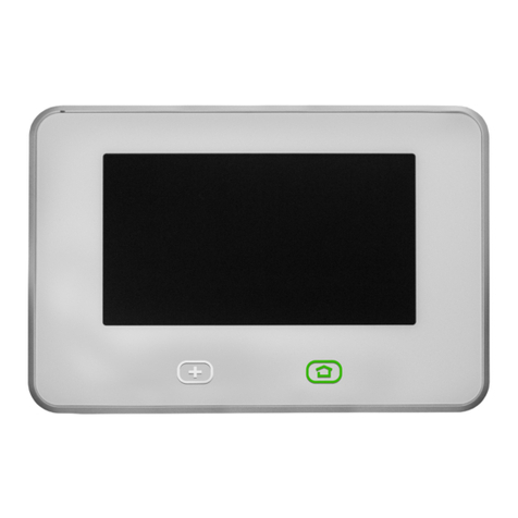
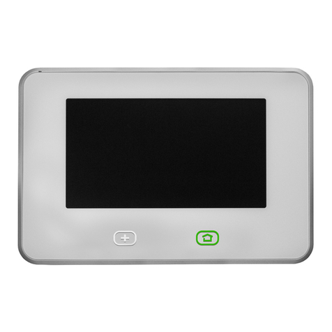
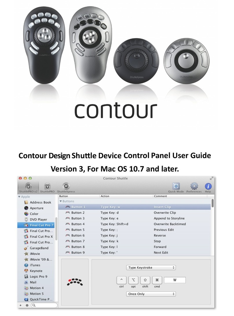
Vivint V-SH1 User manual

SETUP GUIDE
Smart Hub
Panel
a

© 2016 Vivint, Inc. All rights reserved.
VivintanditsrespectivelogosareregisteredtrademarksortrademarksofVivint,Inc.intheUnitedStatesand
othercountries.Allothertrademarksarethepropertyoftheirrespectiveowners.
DISCLAIMER:Nopartofthismaterialmaybeexcerpted,reproduced,redistributed,published,broadcast,transmitted,translated,orutilized
inanyformorbyanymeans,electronic,mechanical,photocopying,recording,orotherwise,withoutpriorwrittenpermissionofVivint,Inc..
Vivintdoesnotwarrantthatthisdocumentiserrorfreeandretainstherighttomakechangestothisdocumentorrelatedproduct
specifications,drawings,anddescriptionsatanytimewithoutnotice.Vivintdoesnotassumeanyobligationtoupdatetheinformation
containedherein.Thisdocumentisprovided"ASIS"andwithoutanyguaranty,warranty,orlicense,expressorimplied,includingbutnot
limitedto:fitnessforaparticularpurpose,merchantability,non-infringementofintellectualproperty,orotherrightsofanythirdparty.
AnyVivintproductsreferencedinthisdocumentarenotintendedforuseinmedical,lifesaving,orlifesustainingapplications.
Thirdpartiesmayhaveintellectualpropertyrightsrelevanttothisdocumentandthetechnologiesdiscussedherein.
Setup Guide
Released:10/17/2016
DocumentPartNumberP/N:77-600017-001—RevA.0
PanelPartNumberP/N:V-SH1
PanelComplianceModelNumberM/N:CP02

- 1 -
Contents
Contents 1
Introduction 3
About this Guide 3
SystemOverview 4
About the System 4
System Configuration Diagram 5
Control Panel Features 6
Control Panel Display Screens 10
SystemSetup 11
System Setup Outline and Summary 11
ConfigureSystemSettings 12
System Settings Configuration Outline 12
System Settings Complete List 13
Security Sensor Numbers and Types 14
Wireless Zones Configuration 17
Wired Zones Configuration 24
Key Fobs Configuration 28
Keypads Configuration 33
Entry and Exit Settings 36
Installer Settings 39
Key Fob Behavior Settings 42
Central Station Settings 43
Reporting and Troubles Settings 45
Emergency Buttons Settings 55
System Options Settings 56
System Registration Settings 59
Z-Wave Settings 60
Networking Settings 63
Cameras Settings 65
System Testing Settings 68
Cellular Settings 71
Sensor Bypass Settings 72
Bell Cutoff Settings 73

- 2 -
Update Settings 74
RegulatoryInformation 75
Where To Find Regulatory Compliance Declarations 75
FCC and IC Regulatory Compliance Declarations 76
Wireless Product Notice 77
Operating Temperature and Humidity Range Notice 77
Important Power Supply Notice 78
Internal Backup Battery Notice 78
Regulatory Notes 79
Applicable Warnings for Technicians 80
Default Settings for SIA CP-01-2014 Compliance 81
FCC and IC ID Numbers for System Devices 83
Fire Protection and Safety Information 84
Service and Warranty Information 88
Specifications 89

Introduction: About this Guide
- 3 -
Introduction
About this Guide
TheVivintSmartHub™panelisthehuboftheVivintSmartHome™system,afully-supervised,integrated,and
intelligenthomesecurityandautomationsystem.
Thesystem—whichincludesthecontrolpanelandvarioussecuritysensorsandperipheraldevices—
incorporatesthemostadvancedandsophisticatedfeaturesandtechnologyavailabletoday.Thesystemcanbe
expandedandcustomizedtofiteveryindividualhomeenvironmentandcustomerneed.
ThisguideprovidesanoverviewoftheentireVivintSmartHomesystem,informationabouthowthedifferent
componentsofthesystemworktogether,importantsafetystandardsandregulatorycompliancedeclarations,
andanoutlineoftheinstallation,setup,andsettingsconfigurationtasks.
Thefollowingtopicsarecoveredinthisguide:
l Learn about the control panelandoverallsystemfunctionality.
l Set up the control panelincludingplugginginthepowersupply,waitingforthepaneltobootup,andthen
followingtheonscreeninstructionsonthepanel'stouchscreendisplaythatstepsyouthroughtheprocess
ofaddingdevices(i.e.,sensors,cameras,etc.)andverifyingsuccessfuldeviceandpanelconnection.
l Configure system settingsforthepanel,securitysensors,andothersmarthomedevices.
NOTE:Somecitiesandmunicipalitiesmayrequireanalarmsystempermit.Checkwiththelocal
authoritiesbeforeinstallingthesystem.
IMPORTANT:AnychangesormodificationsnotapprovedbyVivintcouldvoidtheuser’sauthorityto
operatetheequipment.

Smart Hub Setup Guide
- 4 -
System Overview
About the System
ThissectionprovidesabriefsummaryofthemaincomponentsandfeaturesoftheVivintSmartHubsystem.
Control Panel
TheSmartHubpanelfeaturesacapacitive,colortouchscreendisplaythatallowscontrolofallsystemfunctions
andconfiguration.ThetouchscreendisplayshowstheVivintSmartHomeProtechnician(andthecustomer)
importantinformationsuchassystemanddevicestatus.Thecontrolpanelofferstouchnavigationthatmakes
systeminstallation,configuration,andoperationquickandeasy.
Thecontrolpanelhassystemsoftwareinstalledthatcanbeupdatedwiththelatestreleaseversionthatcan
includefeatureenhancements,fixes,andnewfunctionality.
Security Sensors
Thesystemcansupportupto100wirelesssensorsofvarioustypes(doorandwindowsensors,glassbreak
detectors,motiondetectors,etc.),aswellas20keyfobs,30keypads,and15sensorresponsetypes.
ThecontrolpanelreportssystemalarmsandtroublealertstotheVivintCentralStation(i.e.,MonitoringStation)
viaeithercellularorbroadbandIPnetworkcommunication.Two-wayvoicecommunicationbetweenthepaneland
theCentralStation(VivintLive)isalsoenabledthroughcellularcommunications.
A345MHznarrow-bandradioreceiverinsidethepaneldetectssignalstransmittedfromthewirelesssensors.
Z-Wave Devices
Thepanelhasabuilt-inZ-Waveradiomodulethatprovidessecure,encryptedcommunicationbetweenthepanel
andothersecurity-enabledZ-Wavedevices.Thepanel'sZ-Wavetechnologyallowsthecontrollingandmonitoring
ofvarioushomeautomationdevicessuchasdoorlocks,thermostats,andlightingcontroloutletmodules.
ThecontrolpanelwillworkwithanycompatibleZ-Wavedeviceregardlessofthemanufacturer.
User Accounts
TheVivintsystemsupports50useraccountsincludingasingleDuressUserandoneormoreAdminusers.The
Adminuserscanadd,delete,ormodifytheotherusers.NotethatalluserPINcodesmustbeunique.
TheInstallerPINcodeisassociatedwiththeonlyuseraccountthathasaccesstotheInstaller Toolboxscreens
(usedforconfiguringpanel,device,andsystemsettings).The default Installer PIN code is 2203.
Panel Buttons
ThepanelhasanEmergency buttonandaHome buttonthatfunctionasbothcontrolsandindicators.
Pressingthe buttonatanytimedisplaystheEmergencyscreenwithbuttonsforPanic,Emergency,andFire
alarmactivation(eachbuttonhasconfigurableoptionsandcanbeenabledanddisabledintheInstaller Toolbox).
Pressingthe buttonatanytimedisplaystheHomescreen.

System Overview: System Configuration Diagram
- 5 -
System Configuration Diagram
Thediagrambelowshowstheconfigurationofanoverallsystem—fortheVivintSmartHub™panel—andhow
itsvariouscomponentscommunicateandinteract,includingthecontrolpanel,userinputandinteractionfeatures,
internalmodules,wirelesssecuritysensors,NFC-readysensors(forDIYsetup),Z-Wavedevices,wireless
cameras,remoteaccessandcontroldevices(smartphone,tablet,laptop,etc.)viamobileandwebapps,power
supply,Wi-FicellularandbroadbandIPnetworks,andtheVivintPlatform.
Vivint Smart Hub Panel System

Smart Hub Setup Guide
- 6 -
Control Panel Features
ThefollowingdrawingsshowtwoviewsoftheSmartHubcontrolpanel,withsomeofthemainfeaturescalledout.
First,anexternalfrontview;andsecond,anexternalbackviewofthepanel.
Panel Front View

System Overview: Control Panel Features
- 7 -
Panel Back View

Smart Hub Setup Guide
- 8 -
System Status as Indicated by the Home Button Display
TheHomebuttonLEDcanindicatethestatusofsystemfunctionsandconditions,asdescribedbelow.
Secur ity Sensor Status
l GlowsGreenwhenallofthesensorsareclosedandthesystemisreadytoarm.
l Notlitwhenanysensorisopenandthesystemisnotreadytoarm.
Ar mi ng Status
l GlowsRedwhilethesystemisarmed(ineitherStayorAwaymode).
l FlashesRedduringtheEntryDelaytimeperiod.
Al arm Status
l FlashesRedduringanalarm.
l FlashesRedafteranalarmwhilesystemisstillarmed.
Power Outage Status (on Backup Battery Power)
l FlashesGreenwhenallofthesensorsareclosedandthesystemisreadytoarm.
l FlashesOrangewhenanysensorisopenandthesystemisnotreadytoarm.
l FlashesRedwhilethesystemisarmed(ineitherStayorAwaymode).

System Overview: Control Panel Features
- 9 -
Installer Toolbox Screens
IMPORTANT:ThecompletesetofInstaller ToolboxscreensisaccessibleonlytoaVivintSmart
HomeProstechnicianwhoenterstherequiredInstallerPINcode.
UsetheInstaller Toolboxscreenstoconfiguresystemsettings.TheVivintSmartHomeProtechnicianmust
enteravalidInstallerPINcodetoaccessthistoolbox.Themainscreendisplaysasetofsystemconfiguration
andtestingtools.Usethesetoolstoconfigureallofthesystemsettings,testsystemfunctionality,andreset
systemoptionstodefaultvalues(fordetails,see"ConfigureSystemSettings"onpage12).
FromtheHomescreen,presstheMenubutton>Settings>entertheInstallerPINcode(thedefaultcodeis
2203)>andthenpressInstaller Toolbox.

Smart Hub Setup Guide
- 10 -
Control Panel Display Screens
TheVivintSmartHubpanelisconfiguredandoperatedusingthetouchscreendisplay.Thedisplayshowscritical
systeminformationandprovidesaccesstothenumerousfeaturesusedtoconfigure,monitor,andcontrolthe
homesecurityandautomationsystembyboththeVivintSmartHomeProtechnicianandthehomeowner.
Thestatus baratthetopofthetouchscreenprovidesMenuaccess,andshowssysteminformationsuchasthe
dateandtimeandweatherinformation,aswellasstatusiconsforalerts,messages,power(AC/battery),and
sound.
Thenavigation baratthebottomofthetouchscreenshowsthesecuritymode,andprovidesaccesstothe
connecteddevicessuchasdoorlocks,thermostats,cameras,lightingcontrols,andmore.
TheMenubuttonintheupperleftcornerofthetouchscreenletsyouaccessthefollowingscreens:Emergency,
Settings(includingtheInstaller Toolbox),andSupport.
Home Screen
Atanytime,presstheHomebuttononthetouchscreentoreturntotheHomescreen.

System Setup: System Setup Outline and Summary
- 11 -
System Setup
System Setup Outline and Summary
Thefollowingoutlineprovidesahigh-levelsummaryofallthetasksthatcomprisethesetupofaVivintSmartHub
panelandsystem.
1. Unpack the box.
UnpacktheSmartHubpanelboxandidentifythecontents.Thepackageshouldcontainthecontrolpanel,
powersupply,quicksetupcard,(NOTE:Youcanunpacktheotherdevices,suchassensorsand
cameras,atthistimebutdonotinstallthemyet.)
2. Locate an unswitched outlet for the power supply.
Identifyanunswitchedwalloutletwhereyoucanpluginthepowersupplyforthecontrolpanel.
3. Plug the power supply into the wall outlet.
Plugthepowersupplyintothepreviouslyidentifiedunswitchedwalloutlet.
4. Connect the power supply to the control panel.
Connectthepowersupplycabletotheportonthebacksideofthepanel,andthentuckthecablesnugly
intotheslot.
5. Wait for the panel to start up.
Waitforthepaneltoloadthefirmwareandforthetouchscreeninterfacetoappear.Donotinstallorplace
theperipheraldevicesyet(sensors,cameras,etc.),astheinitialpartofthesystemsetupisdescribedon
thepanelitselfviaonscreeninstructions.Pleasewaitforthepaneltobootupfirst,andforthatinitialsetup
screentoappear.Thisprocessmaytakeafewminutes.
6. Follow the onscreen instructions to add and configure devices.
Oncethepanelisfinishedbooting,followtheonscreeninstructionsthatwillguideyouthroughaddingand
configuringdevices,andfinishingthepanelsetup.
(Formoredetails,seetheseparatedocumententitled"SkyHubPanelDIYOnscreenSetupInstructions")

Smart Hub Setup Guide
- 12 -
Configure System Settings
System Settings Configuration Outline
IMPORTANT:ThecompletesetofInstaller ToolboxscreensisaccessibleonlytoaVivintSmart
HomeProstechnicianwhoenterstherequiredInstallerPINcode.Thissectiondescribesthecomplete
setofsystemsettings(whichmaynotbeavailabletothecustomerviatheUserSettingsinterface).
AstheVivinttechnician,youconfiguresystemsettingsatthecontrolpanelviatheInstaller Toolboxscreens.
Everysystemyouinstallrequiresthatyouconfiguresettingsforcertaininstalledmodulesinthepanel,security
sensorsandotherperipheraldevices,inadditiontospecificsystemfeaturesservices.
Thissectiondescribeshowtoconfigurethesesystemsettings,andprovidesdetailedinformationabouteachof
thesettingsincludingdefaultvalues,functionality,andcompliancerequirementsfortheAmerican National
Standards Institute / Security Industry Association,ANSI/SIA CP-01-2014standard,hereafterreferredtoin
itsabbreviatedformasSIA CP-01-2014.
Somesystemsettingsarecommonacrossallinstallations(forexample,allcontrolpanelsreporttothesame
CentralStation).Othersettings,suchasaccountnumberandsensoranddeviceconfiguration,areuniquetoeach
installation.Followtheprocedurebelowtoguideyouthroughthesystemsettingsconfiguration.
To configure system settings
1. AtthepanelHomescreen,presstheMenubutton>andthenpressSettings.
2. EntertheInstallerPINcode(thedefaultcodeis2203).
3. PressInstaller Toolbox.
4. Tobeginconfiguringthesystem,pressZones, Key Fobs, Keypads,andthenpressWireless Zonesto
addandthenconfigurethewirelesssecuritysensorsthatareincludedinthisinstallation.
Formoreinformation,see"WirelessZonesConfiguration"onpage17.
5. Ifyou'reinstallinganywiredsensors,pressWired Zonestoaddandthenconfigurethosesensors.
Formoreinformation,see"WiredZonesConfiguration"onpage24.
6. Ifthesystemincludeskeyfobsand/orkeypads,addandthenconfigurethosedevices.
Formoreinformation,see"KeyFobsConfiguration"onpage28,and"KeypadsConfiguration"onpage33.
7. IMPORTANT:Keepinmindthateveryinstallationisunique—basedonthelocalnetwork,numberand
typeofsensorsandperipheraldevicesbeinginstalled,environmentalfactors,theresultingoptimalsystem
designandconfiguration,andotherconsiderations.Refertothecompletelistofsettingsbelowfor
informationabouthowtoconfigureeachcomponentandfeatureavailablefortheentiresystem.
Formoreinformation,see"SystemSettingsCompleteList"onthefacingpage.
8. Afterconfiguringallofthesettingsrequiredforthisinstallation,presstheHomebuttontoreturntothe
Homescreen.(NOTE:Allsettingschangesareautomaticallysavedinsystemmemoryinrealtimewhen
thechangeismade.)

Configure System Settings: System Settings Complete List
- 13 -
System Settings Complete List
Usethelistbelowasaquickreferencetodetailedinformationaboutallofthesystemsettings.
Toaccessthesecuritysensorandremotecontroldevicesettingsfromthecontrolpanel,goto:
Menu > Settings > Installer Toolbox > Zones, Key Fobs, Keypads
Andthenselectfromthefollowing:
l "WirelessZonesConfiguration"onpage17
l "WiredZonesConfiguration"onpage24
l "KeyFobsConfiguration"onpage28
l "KeypadsConfiguration"onpage33
Formoreinformationaboutconfiguringsensors,see"SecuritySensorNumbersandTypes"onthenextpage.
Toaccessallothersystemsettings,goto:
Menu > Settings > Installer Toolbox
Andthenselectfromthefollowing:
l "EntryandExitSettings"onpage36
l "InstallerSettings"onpage39
l "KeyFobBehaviorSettings"onpage42
l "CentralStationSettings"onpage43
l "ReportingandTroublesSettings"onpage45
l "EmergencyButtonsSettings"onpage55
l "SystemOptionsSettings"onpage56
l "SystemRegistrationSettings"onpage59
l "Z-WaveSettings"onpage60
l "NetworkingSettings"onpage63
l "CamerasSettings"onpage65
l "SystemTestingSettings"onpage68
l "CellularSettings"onpage71
l "SensorBypassSettings"onpage72
l "BellCutoffSettings"onpage73
l "UpdateSettings"onpage74

Smart Hub Setup Guide
- 14 -
Security Sensor Numbers and Types
Eachsecuritysensorinstalledaspartofthesystem—whetherwirelessorwired—isconfiguredtocorrespondto
aspecificsensor numberandsensor type (i.e., zone).
Sensor Numbers
Thesensor numberidentifiesthespecificsensor,andisusedwhenthesensoris:
l displayedonthecontrolpanel
l recordedintheeventlog
l reportedtotheCentralStation
Thisprovidespreciseinformationabouteverysecuritysensorinthesystem.
Sensor Types
Thesensor type(sometimesreferredtoasasensorzone)determineshowandwhenthecontrolpanelresponds
tosignalsfromthesensor.Somesensorsarearmedallthetime,othersarearmedonlyincertainarminglevels,
andsomesensorscauseCentralStationreportsanytimetheyareactivated.Thesensortype,alongwithother
configurationoptions,determinethisbehavior.
Thefollowinglistdescribeseachofthesensortypes/zones.
(00) Unused
Thisisthesettingforunusedsensornumbersthatdonothaveasensorconfiguredintothem.Nosystemaction
occursatanytimefromthissensortype.
(01) Exi t/Entry 1
Thissensortypeisreservedfordoorsthatareusedforexitandentry.WhenthesystemisarmedintheAway
ModeorStayMode,theExitDelaytimerstarts.ThereisanExitDelayregardlessofwhetherthesystemisarmed
inStayModeorAwayMode.WhentheExitDelaytimerexpires,thesystemisfullyarmed.
Withthesystemfullyarmed,whenthistypeofsensoristriggered,theEntryDelay#1timerstarts.Thesystem
mustbedisarmedbeforetheEntryDelay#1timeexpires,oranalarmwilloccur.
IftheEntryDelayisturnedoffbydisablingEntryDelayfromtheArmingscreenwhenarmingthesystem,theexit/
entrydelaysensorswillinstantlytriggeranalarmaftertheendofExitDelay(whenthesensoristriggered).
(02) Exi t/Entry 2
ThissensortypeoperatesthesameastheExit/Entry1sensortypeexceptitwillstarttheEntryDelay#2timer.
ThisprovidesamethodofhavingalongerEntryDelayoncertainopenings,suchasagaragedoor,toprovidethe
usermoretimetodisarmthesystem.
(03) Per imeter
Thissensortypeisforsensorsthatprotecttheperimeterofthepremises,suchasawindowsensor.Perimeter
sensorsinstantlytriggeranalarmwhenopenedwhilethesystemisarmedawayorstay.

Configure System Settings: Security Sensor Numbers and Types
- 15 -
(04) Interior Fol l ower
Thissensortypeisforinteriorsensorssuchasmotiondetector,interiordoors,andothersensorsthatdetect
humanpresenceinsidetheprotectedarea.Thistypeofsensoriscalleda"follower"duetoitsactionwhenthe
systemisarmedintheAwayMode.AftertheExitDelayexpiresandthesystemisarmed,ifaninteriorfollower
sensoristriggered,aninstantalarmwilloccur.
InteriorfollowersensorsarealwaysbypassedandnotactivewhenthesystemisarmedinStayMode.This
allowstheprotectedareatobeoccupiedwhilestillprotectingtheperimeter.
(05) Day Zone
Thissensortypeisthesameasaperimeterzone,exceptwhenthesystemisdisarmed,openingthesensor
displaysatroublealertonthecontrolpaneldisplay.Commonusesforthissensortypeareprotectionofsensitive
areasthatrequirenotificationandpossiblyaCentralStationtroublereport,butnotanalarmwhenthesystemis
disarmed.
(06) 24-hour Sil ent Al arm
Thissensortypeisactiveindependentofthesystemarmingstatus.Thecodeforsilentpanicissenttothe
CentralStation,butforsafety,therearenovisualoraudibleindicationslocallythatthissensortypehasbeen
triggered.
(07) 24-hour Audi ble Alarm
Thissensortypeiscontinuouslyarmed24-hoursaday.Asensorconfiguredtothistypewilltriggeralocalalarm
andtheexternalsirenregardlessofthemodethesystemisin.Typicaluseofthissensortypewouldbeanaudible
panicalarm.
(08) 24-hour Auxi liary Alarm
Thissensortypeiscontinuouslyarmed24-hoursaday.Asensorconfiguredtothistypewilltriggeranalarm
regardlessofthemodethesystemisin.Theexternalsirenwillnotactivate,butthelocalsounderwillcontinue
untilit’sacknowledgedatthecontrolpanel.Typicalusewouldbeforamonitoringdevicesuchasafloodor
temperaturesensor.Thereisnotimeoutfortheinternalsounder,itwillcontinueuntilauserPINcodeisentered.
(09) 24-hour Fir e **
Thissensortypeiscontinuouslyarmed24-hoursaday.Asensorconfiguredtothistypewilltriggerthelocalalarm
firesounderandtheexternalsirenregardlessofthemodethesystemisin.Typicalusewouldbeforwireless
smokedetectors.Thissensortypeisalwaysactiveandcannotbebypassed.
(10) Interior wi th Delay
ThissensortypeoperatesasadelayedsensorwhenthesystemisarmedintheAwayMode,andwhentriggered,
willstarttheEntryDelay#1timer.IfthesystemisarmedinAwayModewithnoEntryDelay(armedinstant),this
sensortypewilltriggeraninstantalarm.
IfthesystemisarmedinStayMode(orStayModewithnoEntryDelay),thissensortypewillbebypassed.
(14) 24-hour Carbon Monoxi de **
Thissensortypeiscontinuouslyarmed24-hoursaday.Asensorconfiguredtothistypewilltriggerthelocalalarm
pulsesounderandtheexternalsirenregardlessofthemodethesystemisin.Typicalusewouldbeforwireless
carbonmonoxidedetectors.Thissensortypeisalwaysactiveandcannotbebypassed.

Smart Hub Setup Guide
- 16 -
(16) 24-hour Fir e with Veri f ication **
Thissensortypeiscontinuouslyarmed24-hoursaday.Asensorconfiguredtothistypecantriggerthelocalalarm
firesounderandtheexternalsirenregardlessofthemodethesystemisin.Typicalusewouldbeforwireless
smokedetectors.Thissensortypeisalwaysactiveandcannotbebypassed.
Forverification,thissensortypemustbeviolatedtwiceintwominutes,orremainviolatedfor30seconds.Ifany
otherfiresensor(verifiedsensortypeornot)violateswithintwominutes,bothsensorswillcauseafirealarm.
(23) No Response Type
ThissensortypeisaspecialzonethatcanbemonitoredforactivityorinactivitybytheCentralStation.Itdoesnot
affectsecuritysystemstatus.
(24) Sil ent Burglary
Thissensortypeisforsilenttriggeringtheburglaryalarmwithperimeterdoorsandwindowsthatwillnotbeused
toenterorexittheprotectedareawhilethesystemisarmed.Thecontrolpanel’salarmsounderandtheexternal
sirenwillnotactivate.
AninstantsilentalarmwilloccurwhenthistypeofsensoristriggeredwiththesystemarmedineithertheStay
ModeorAwayMode.
(25) Repeater
ThissensortypeisforrepeatermodulesthatconsistofbothanRFreceiverandtransmitterandthatareusedto
extendtherangeofwirelessdevicesintheeventtheyarelosingpanelsupervision.
**Indicatessensortypesthatarenotallowedtobeusedwiththehardwireloops.

Configure System Settings: Wireless Zones Configuration
- 17 -
Wireless Zones Configuration
Thissectioncontainsdescriptions,defaultvalues,andnotesabouttheWirelessZonessettings.
Toaccessthesesettingsfromthecontrolpanel,goto:
Menu > Settings > Installer Toolbox > Zones, Key Fobs, Keypads > Wireless Zones
List of Settings
Theoptionsthatcanbesetforeachwirelesssensorincludethefollowing(seebelowthislistfordetailed
descriptions):
l Equipment Code: Sensormodel(door/windowsensor,PIRmotionsensor,smokedetector,etc.).
l Other Equipment Code: Enterspecialequipmentcode(onlyshownforsensorssetas"Other").
l Sensor Type: Exit/entry,perimeter,interior,etc.
l Equipment Type: Certainsensortypeswillaskforequipmenttype(seethelistbelow).
l TXID: TXIDnumberlabeledonthesensor(manuallyenterorlearnin).
l Loop: Built-incontactsorexternalcontactsondoor/windowsensor.
l Voice Descriptor: Selectthewordsthepanelvoiceusestodescribethesensor.
l Name: Nameassignedtothesensorthatisusedforvoiceannunciationandinuserinterfaces.
l Chime: Enableanddisablethechimeoptionforthesensor.
l Chime Tone:Selectfromtheavailabletonesforthechime.
l Voice:Enableanddisablethevoiceoptionforthesensor.
l Dialer Delay: Delayedorinstantcommunicatorreportsforthesensor(delaytimeissetbydialerabort
window.)
l Reports: Communicatorreportsornocommunicatorreportsforthesensor.
l Supervised: Panelchecksforstatusreportsfromthesensor,ordoesnotcheckforstatusreports.
l Equipment Age: Identifiesthesensoraseitheranewdevice(i.e.,addedduringtheinitialinstallation)or
anexistingdevicethatwaspreviouslyinstalledinthesystem.
l Zone Number: Selectanumberfrom01to100.
l Secure Mode: Indicateswhetherthesensorhasbeenconfiguredwithanti-theftsecurityencryption.
l 32 Bit ID: Automaticallyassignedidentificationnumberforsensorsthatareencryptedwithanti-theft
security.
l Battery Life: Indicatesthepercentageofpowerremaininginthesensor'sbattery.
l Battery Level: Showsthelevelofvoltageremaininginthesensor'sbattery.
l Last Battery Measurement Time: Showsthedateandtimeofthemostrecentsignalfromthesensorthat
providedinformationaboutthestatusofthesensor'sbattery.

Smart Hub Setup Guide
- 18 -
l Battery Threshold: Whenthesensor'sbatterylevelfallsbelowthisvalue,alowbatterysignalwillbe
sentfromthesensortothepanel.
l Cold Climate: Enableanddisablethecoldclimateoptionforthesensor'sbatterythataccountsfora
colderenvironmentandpreventsfalse(i.e.,inaccurate)reportsofalowbatterysignalsentbythesensorto
thepanel.Forexample,ifyouinstallthesensorinacoldclimate,oranywhereinthehomewhereitis
typicallycolderthannormal,thesensormighttransmitsignalsindicatingthebatterylevelislowerthanit
actuallyis.Thisoptionletsyoupreventthosefalsereportsbyenablingadifferentformulaformeasuring
thebatterylevel.
l Cold Climate Season (in days): Letsyoucustomizethedurationofthecoldclimateseasonby
specifyingthenumberofdays.
l Single RF Quiet Chatter: Eliminatessignalchattercreatedwhenbothanindividualsensorandarepeater
devicesendredundantsignalstothepanel.
Wireless Sensor Equipment Code
Theequipmentcodeisa4-digitcodethatisassignedtothemodelofsensorbeingused.Thecontrolpanel
displaysalistofsensormodelsandtheirassociated4-digitequipmentcode.
1. Selectthemodelofwirelesssensorbeingconfiguredforthissensornumberbyselectingtheequipment
codefromthelistorbyenteringtheequipmentcodenumberdirectlyonthekeypad.
NOTE:Whenyouselectthesensor'sequipmentcode,defaultvaluesforsomeofthesensor'sother
optionsareautomaticallyset.Makesuretoconfirmthatthedefaultsettingsmatchthedesired
configuration.
2. Ifthesensormodelisnotinthelist,select(0000) Other.Theequipmentcodeforthissensorcanbe
enteredusingtheresultingsub-option,calledtheOther equipment code.
Wireless Sensor Equipment Codes
(0000)Other (2081)RPTR1-345VivintRepeater
(1251)DW11Door/Window(NGP device) (1144)RE220T2GIGRepeater
(1252)DW21RRecessedDoorContact(NGP device) (0655)ExistingDoor/WindowContact
(1249)PIR2MotionDetector(NGP device) (0609)ExistingMotionDetector
(1248)GB2GlassBreakDetector(NGP device) (0475)ExistingGlassBreakDetector
(1253)PANIC2PanicPendant(NGP device) (0616)ExistingSmokeDetector
(1058)SMTK3SmokeDetector (0708)ExistingHeatSensor
(1026)2GIGCODetector (0692)ExistingCODetector
(1061)GARAGE01RPTiltSensor (0556)ExistingFlood/TempSensor
(1063)DBELL12GIGDoorbell (0862)DW10ThinDoor/Window
Table of contents
Other Vivint Control Panel manuals
Popular Control Panel manuals by other brands
tau
tau K100M installation guide

Spectron
Spectron spectrocem BE55-1 user manual
Side-Power
Side-Power S-linkControl Panel PJC222 Installation and user manual
SILENT KNIGHT
SILENT KNIGHT IFP-1000 Basic operating instructions
BFT
BFT ALTAIR-P Installation and user manual
INIM Electronics
INIM Electronics Previdia Compact Manual for system configuration, commissioning and maintenance
