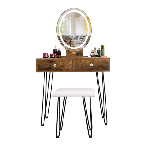
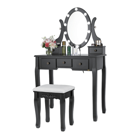
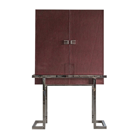
VIVO HOME VH961 User manual

VANITY SET WITH
STORAGE CABINET
Assembly Instructions
V-2

•
•
•
•
•
•
•
•
•
The product must be assembled and used in accordance with the provisions of the
manual.
Avoid long-term exposure to humid environments to prevent mildew.
Keep the product away from re sources and high temperatures. Do not expose the
product to direct sunlight.
Do not place any hot objects directly on the surface of the product.
If there are any defective or missing parts after unpacking, please cease assembly
immediately and contact us.
Please assemble the item on a spacious surface; to aviod product damage, do not
place the unwrapped product directly on the ground.
Please do not stand or sit on the wooden boards.
Please keep the product away from sharp, pointed objects and corrosive substances
to prevent product damage.
If you nd that the table legs are loose during use, please tighten the screws as soon
as possible to prevent the issue from persisting.
•
•
Children are not allowed to assemble the product. During assembly, keep all small
parts out of the reach of children, as it may be fatal to swallow or inhale them.
Children are forbidden to climb or play on the product. Climbing or playing on the
product may result in serious bodily injuries.
-1-
Note
Warning
Attention
For your safety, we suggest securing the anti-tip accessories to the wall to
prevent tipping, injuries, and property damage.

-2-
Parts List and Diagram
1
2
X1
X1
Item no. Reference Image Qty.
6
7
X1
X1
Item no. Reference Image Qty.
3X1 8X1
5X1 10 X1
4X1 9X1

-3-
Parts List and Diagram
11
12
X1
X2
Item no. Reference Image Qty.
16
17
X2
X2
Item no. Reference Image Qty.
13 X2 18 X2
15 X2 20 X2
14 X2 19 X2

-4-
Parts List and Diagram
21
22
X2
X1
Item no. Reference Image Qty.
23 X1
X42
Item no. Reference Image Qty.
0.5*0.4 in. (L*W)
M4*0.6 in. (L*W)
M3.5*0.5 in. (L*W) M3*0.6 in. (L*W)
0.2*1.6 in. (L*W)
M6*1.0 in. (L*W)
X42 X4
B G
A
X8 X4
C H
X4 X4
D J
X92 X4
E K
L
X20 X1
F
M6*25mm
M3*14mm
M4*14mm
M3.5*12mm
12*10mm
30.5mm
5*40mm
600mm
400mm
150mm
12in
23.6in
15.8in
6.0in
LED/USB

10.5*6.5 in. (L*W) M5*0.4 in. (L*W)
-5-
Parts List and Diagram
Item no. Reference Image Qty. Item no. Reference Image Qty.
X1 X2
P
X20
M
X2 X1
NQ
Use The Cam Lock and Quickt
Quickt: Tighten the quickt until it is
ush against the panel. Do not under-
or over-tighten it.
The cam lock should be inserted before
the quickt. Turn the cam lock clockwise
to tighten. The head of the quickt
should be inserted in the center of the
cam lock where the two panels are
joined.
Adhesive Screw Covers
X1
assembly tools
M6*12/M6mm
M5*10mm265*165mm
*Package includes some extra screws

-6-
Assembly Steps
STEP 2
8
8
x 1 pc. x 20 pcs.
E
STEP 1 x 4 pcs.
J
J
E
JJ
JJ
X4
Assemble a footpad onto Part J. Repeat this process three more times so that there
are four total cabinet legs.
Use Parts E (20 pcs.) to x Parts J (4 pcs.) on Board 8, as shown in the gure. First, insert
Parts E (12 pcs.) into the pre-drilled holes of both Parts J and Board 8. Then, insert
Parts E (8 pcs.) through the remaining holes of Parts J (note: there are no pre-drilled
holes at these locations on Board 8—the user must use force to insert the screws).
There should be ve Parts E per one Part J.

-7-
Assembly Steps
STEP 4
9
9
x 1 pc. 10 x 1 pc.
10
x 4 pcs.
C1 x 8 pcs.
E
STEP 3 x 8 pcs.
C
C1 C2
C1
C1
C1
C1
E E
Divide each Part C into Part C1 (with double sliding rails) and Part C2
(with a single sliding rail).
Use Parts E to x Parts C1 (with double sliding rails) on Board 9 and Board 10. Use two
Parts C1 per each board and two Parts E per Part C1. Please pay attention to the
direction of Parts C1 and the position of the small holes on Board 9 and Board 10.

-8-
Assembly Steps
STEP 6 x 4 pcs.
Ax 4 pcs.
B
A
1
2
A
1
2
STEP 5
11
x 1 pc.
11
x 4 pcs.
A
A A
x 4 pcs.
B
BB
10
10
11
9
9
8
180°
10
9
B
A
B
Use Parts A and Parts B to connect Board 11 with Board 9 and Board 10, as shown
in the gure.
Use Parts A and Parts B to connect Board 8 with Board 9 and Board 10, as shown
in the gure.

-9-
Assembly Steps
STEP 8
7
x 1 pc. x 4 pcs.
A
A
A
x 4 pcs.
B
STEP 7 22
22
x 1 pc.
10
9
8
7
9
10
BB
2
1
Slide Board 22 into the grooves of Board 8, Board 9, and Board 10.
Use Parts A and Parts B to connect Board 7 with Board 9 and Board 10, as shown
in the gure.

-10-
Assembly Steps
STEP 10 14
19 14
x 2 pcs.
13
18 13
x 2 pcs. 19 x 2 pcs.
18 x 2 pcs.
x 8 pcs.
C2 x 16 pcs.
E
STEP 9 x 4 pcs.
K
22
K
22
K
22
K
//
EE
19 14
/
C2
18 13
/
E
E
C2
Insert Parts K into the gap between Board 22 and Boards 8, 9, 10, and 7. Use the
paired screws to x Parts K on Board 22.
Use Parts E to x Parts C2 (with a single sliding rail) on Boards 13, 14, 18, and 19.
Use one Part C2 per each board and two Parts E per Part C2. Please pay attention to
the direction of Parts C2 and the position of the small holes on each board.
X2

-11-
Assembly Steps
STEP 12 16
16 21
x 2 pcs. 21 x 2 pcs.
STEP 11 20 x 2pcs.
15 x 2pcs. x 16 pcs.
F
F
F
19
14
18
13 20 15
/
/
20 15
/
/
18
13
/
/
19
14
/
Use Parts F (4 pcs.) to connect Board 15 with Board 13 and Board 14. Repeat this step
to get two identical parts.
Use Parts F (4 pcs.) to connect Board 20 with Board 18 and Board 19. Repeat this step
to get two identical parts.
Note: The sliding rail faces outwards. Please pay attention to the direction of grooves
on each board, as shown in the gure.
Slide Board 16 into the grooves of Board 13, 14, and 15. Repeat this step to get two
identical parts.
Slide Board 21 into the grooves of Board 18, 19, and 20. Repeat this step to get two
identical parts.
X2
X2

A
12
3
-12-
Assembly Steps
STEP 14 x 4 pcs.
D
D
STEP 13 12 x 2 pcs. 17 x 2 pcs. x 16 pcs.
Ax 16 pcs.
B
Adhesive Screw Covers x 16 pcs.
17 12
B
B
/
A
17
12
/
Use Parts A (4 pcs.) and Parts B (4 pcs.) to connect Board 12 with Board 13 and Board 14.
Repeat this step to get two identical drawers. Use Parts A (4 pcs.) and Parts B (4 pcs.)
to connect Board 17 with Board 18 and Board 19. Repeat this step to get two identical
drawers. Use adhesive screw covers to cover the mounting holes of Parts B.
Use the paired screws to x Parts D on Boards 12 and Boards 17. Use one Part D per
each board.
X2
X4

-13-
Assembly Steps
STEP 16
4
x 1 pc.
5
x 1 pc. x 2 pcs.
C1 x 4 pcs.
E
STEP 15
E E EE
4 5
C1 C1
C1 C1
Slide the completed two drawers into the cabinet.
Use Parts E to x Parts C1 (with double sliding rails) on Board 4 and Board 5. Use one
Part C1 per each board and two Parts E per Part C1. Please pay attention to the
direction of Parts C1 and the position of the small holes on Board 4 and Board 5.

STEP 17
6
x 1 pc. x 2 pcs.
C1 x 4 pcs.
E
-14-
Assembly Steps
A
12
3
STEP 18
3
x 1 pc. x 4 pcs.
Bx 2 pcs.
F
x 4 pcs.
A
Adhesive Screw Covers x 4 pcs.
3
B
B
F
4
6
5
A
6
E
E
E
E
C1
C1
Use Parts E to x Parts C1 (with double sliding rails) on the two sides of Board 6
(i.e., x one Part C1 and use two Parts E on each side). Please pay attention to the
direction of Parts C1 and the position of the small holes on Board 6.
Use Parts A, Parts B, and Parts F to connect Board 3 with Board 4, 5, and 6, as shown
in the gure. Use adhesive screw covers to cover the mounting holes of Parts B.

STEP 20
1
1
x 1 pc. x 6 pcs.
A
A
A
1
-15-
Assembly Steps
A
12
STEP 19
2
2
x 1 pc. x 4 pcs.
Bx 2 pcs.
F
x 4 pcs.
A
A
A
B
B
90°
F
Use Parts A, Parts B, and Parts F to connect Board 2 with the assembled section from
Step 18.
Assemble Parts A on Board 1.

-16-
Assembly Steps
STEP 21 x 6 pcs.
B
1
2
B
B
B
B
B
B
6
5
4
1
A
STEP 22 x 4 pcs.
G
GX4
Insert Parts A into the pre-drilled holes on Board 4, Board 5, and Board 6. Use Parts
B to x the entire cabinet.
Assemble a footpad onto Part G. Repeat this process three more times so that there
are four total table legs.

-17-
Assembly Steps
STEP 23 x 10 pcs.
E
180°
E
E
2
G
G
Note: This dressing table has two assembly methods, as shown in the gure.
If you want a dressing table like the
left gure, please follow Steps 23 - 25.
If you want a dressing table like the
right gure, please follow Step 26.
You must follow Steps 27 - 31 to complete the nal assembly regardless of which assembly
method you choose.
Use Parts E (10 pcs.) to x Parts G (2 pcs.) on Board 2, as shown in the gure. First,
insert Parts E (6 pcs.) into the pre-drilled holes of both Parts G and Board 2. Then,
insert Parts E (4 pcs.) through the remaining holes of Parts G
(note: there are no pre-drilled holes at these locations on Board 2—the user must
use force to insert the screws). There should be ve Parts E per one Part G.

-18-
Assembly Steps
STEP 25
STEP 24
180°
Flip the table 180° so that it is right-side up. Place it on the cabinet. Note: the table
may slide o if the user excessively pushes or pulls the vanity set.
Slide the completed two drawers into the table.

-19-
Assembly Steps
STEP 27 x 1 pc.
Lx 2 pcs.
N
N
N
STEP 26 x 20 pcs.
E
E
L
2
G
GG
G
Use Parts E (20 pcs.) to x Parts G (4 pcs.) on Board 2, as shown in the gure. First,
insert Parts E (12 pcs.) into the pre-drilled holes of both Parts G and Board 2. Then,
insert Parts E (8 pcs.) through the remaining holes of Parts G (note: there are no
pre-drilled holes at these locations on Board 2—the user must use force to insert the
screws). There should be ve Parts E per one Part G.
Use Parts N to connect the base of Part L with the mirror frame of Part L.
Table of contents
Other VIVO HOME Indoor Furnishing manuals
Popular Indoor Furnishing manuals by other brands

Costway
Costway HV10418 manual
Seconique
Seconique OAK EFFECT NAPLES STORAGE SIDE TABLE Assembly instructions

Forte
Forte Lena SNNK221 Assembling Instruction
Allen + Roth
Allen + Roth EFC11-SS09 manual

Furniture of America
Furniture of America CM7688Q Assembly instructions

Kinfine
Kinfine HOMEPOP K6410 Assembly instructions

wildkin
wildkin Rocking Horse Assembly instructions

Twin-Star International
Twin-Star International 36BV34004 manual

Bestar
Bestar 60510-2163 Assembly instructions
CALICO DESIGNS
CALICO DESIGNS DEVONPORT 52001 Assembly instructions
Mercado Medic
Mercado Medic REAL 9500 INSTRUCTIONS FOR ASSEMBLY, USE & CARE
STRUCTUBE
STRUCTUBE JAY quick start guide
