Vivo STAND-RACE1B User manual

Racing Simulator
Cockpit
Instruction Manual
SKU: STAND-RACE1B/BL
Assembly Video & Product Info
www.vivo-us.com/products/stand-race1b

2
If you do not understand these directions, or if you have any doubts about the safety of the installation, please
contact our product support team at 309-278-5303 or [email protected] for further assistance. Check carefully to
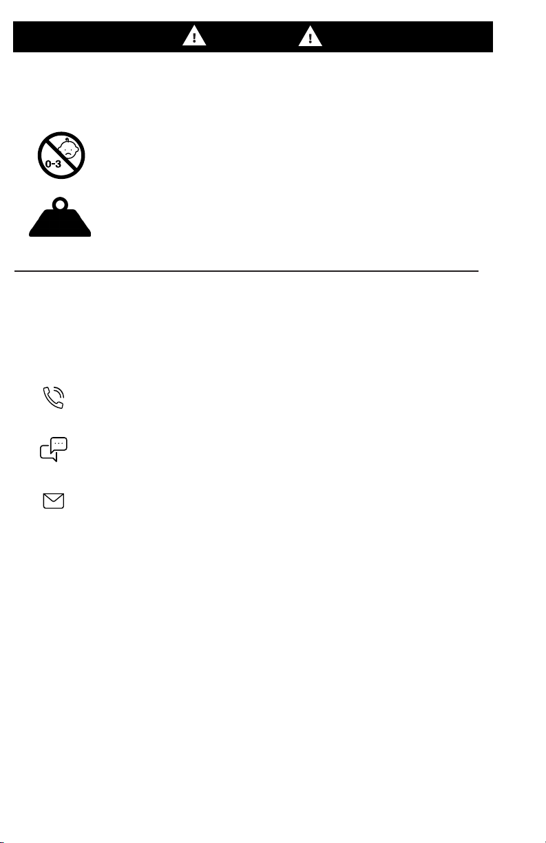
make sure there are no missing or defective parts. Improper installation may cause damage or serious injury. Do not
use this product for any purpose that is not explicitly specified in this manual. Do not exceed weight capacity. We
cannot be liable for damage or injury caused by improper mounting, incorrect assembly or inappropriate use.
LBS
CAUTION!
WARNING: CHOKING HAZARD
SMALL PARTS - NOT FOR CHILDREN UNDER 3 YEARS. ADULT SUPERVISION IS REQUIRED.
DO NOT EXCEED WEIGHT CAPACITY
FAILURE TO DO SO MAY RESULT IN SERIOUS INJURY.
We’re Here for You
Open Monday - Friday 7:00am - 7:00pm CST,
our dedicated support team can oer immediate assistance with rapid response times. If any
parts are received damaged or defective, please contact us. We are happy to replace parts to
ensure you have a fully functioning product.
Chat Us:
www.vivo-us.com
Give us a Call:
309-278-5303
Email Us:
- 23% within < 15m
- 38% within < 30m
- 61% within < 1hr
- 83% within < 2hr
- 92% within < 3hr
AVG. RESOLUTION TIME (within oice hrs): < 15 M
AVG. RESOLUTION TIME (within oice hrs): 5M 4S

3
Package Contents
A (x1)
Front Support
Frame
B(x2)
Side Support Bar C(x1)
Rear Support Bar
D(x2)
Support Bar
Spacer
E(x1)
Right Brace
G(x1)
Footrest
H (x1)
Wheel Mount
I (x1)
Right Chair
Support with Lock
J (x1)
Le Chair
Support L(x1)
Chair Back
M(x1)
Right Side
Cover
N(x1)
Le Side
Cover
O (x4)
Foot Pad P(x1)
Shier Support Bar
Q(x1)
Shier Mount
R(x4)
Cable Clip
S(x6)
Ziptie
F (x1)
Le Brace
K (x1)
Chair Seat

4
Phillips
Screwdriver
Included Hardware & Tools
Tools Needed: Weight Capacity:
220lbs
(100kg)
22lbs
(10kg)
S-A (x4)
Spacer
S-B (x4)
M8x30mm Hex
Head Screw with
Washers
S-C (x4)
M5x8mm
Screw
S-D (x22)
M8x16mm
Screws
S-E (x4)
M8x30mm
Screws
S-F (x2)
M8x60mm
Screws
S-G (x2)
M6x15mm
Screws
S-H (x2)
M8x50mm
Screws
S-I (x2)
M8 Nut
T-A (x1)
5mm Allen
Wrench
T-B (x1)
Wrench
Seat Gear Shi

5
ASSEMBLY STEPS
STEP 1
Screw two Foot Pads (O) into the underside of Front Support Frame (A).
Place one Support Bar Spacer (D) onto the front, angled end of each Side Support Bar (B),
then connect to the Front Support Frame (A) using M8x60mm Screws (S-F). Tighten using
5mm Allen Wrench (T-A).
O
A
S-F (x2)
T-A
B
D
S-F
T-A

6
STEP 2
Screw remaining Foot Pads (O) into Rear Support Bar. Then insert the Side Support Bars
(B) into the Rear Support Bar (C), and secure using M8x16mm Screws (S-D) and 5mm
Allen Wrench (T-A).
S-D (x8)
STEP 3
Remove pre-installed Screws (A-1) from Front Support Frame (A). Assemble Right and Le
Braces (E, F) to the frame using previously removed Screws (A-1), M8x16mm Screws (S-D) and
5mm Allen Wrench (T-A).
S-D (x4)
C
B
T-A
OS-D
T-A
A-1
S-D
T-A
T-A
T-A A
F
A-1
E

7
STEP 4
Insert M8x16mm Screws (S-D) into the front holes of Footrest (G) and Front Support
Frame (A) to hold Footrest at one of three heights, as shown below. Tighten all Screws
using 5mm Allen Wrench (T-A).
1. Top Hole 2. Middle Hole
Install the Footrest (G) to the Front Support Frame (A) using M8x16mm Screws (S-D) and 5mm
Allen Wrench (T-A). Ensure Screws go into the rear mounting holes on Footrest.
3. Lower Hole
G
A
S-D
Insert Screws into the
rear mounting holes on
Footrest
S-D (x2)
T-A
S-D (x2)
T-A
S-D
T-A
G
A

8
STEP 5
Attach Wheel Mount (H) to Front Support Frame (A) using M8x16mm Screws (S-D) and
5mm Allen Wrench (T-A).
Adjust the wheel mount height and angle by removing the pre-installed bolts with
washers from the sides, then reinstall while holding the mount at the desired height and
angle.
S-D
H
T-A
S-D (x2)
T-A

9
STEP 6
Extend the Slider (I-1) on Right Chair Support with Lock (I) by liing on the Lever (I-2) and
pulling forward.
Pull and extend Slider (J-1) forward on Le Chair Support (J).
I
J-1
J
I-1 I-2

10
Connect Right and Le Chair Supports (I, J) to the Chair Seat (K) using Spacers (S-A)
and M8x30mm Screws (S-E) into to front holes on Sliders (I-1, J-1) with 5mm Allen
Wrench (T-A).
Slide Supports (I, J) forward to reveal rear mounting hole. Secure using Spacers (S-A),
M8x30mm Screws (S-E), and 5mm Allen Wrench.
S-E (x2)
S-A (x2)
T-A
STEP 7
K
S-A
S-E
T-A
I
J
J
I
S-A (x2)
T-A
S-E (x2)
S-E
T-A

11
STEP 8
Mount Chair Seat (K) with Supports to assemble frame using M8x16mm Screws (S-D)
with 5mm Allen Wrench (T-A).
STEP 9
Assemble Chair Back (L) to Side Brackets (K-1) on Chair Seat (K) using M8x30mm Hex Head
Screw with Washers (S-B) and a Phillips screwdriver. Install Le and Right Side Covers (M, N) to
Brackets using M5x8mm Screw (S-C), and tighten with a Phillips screwdriver.
S-D (x4)
T-A
K
S-D
T-A
S-B (x4)
S-C (x4)
K-1
S-C
S-B
M
N
T-A

12
STEP 10.1
The Shier Mount can be installed on either the right or le side, based on your preferences.
Follow the steps outlined below and on the next page to assembly to your desired side.
OPTION A: Right Side Shi Lever
Attach Shier Mount (Q) to the top of Shier Support Bar (P) using M6x15mm Screws (S-G),
making sure the long end of Mount is in the back, and tighten with a Phillips screwdriver.
Connect the Shier Support Bar (P) to the right side of the frame using M8x50mm Screws (S-H)
and M8 Nuts (S-I). Tighten using 5mm Allen Wrench (T-A) and Wrench (T-B).
S-G
Q
P
S-G (x2)
S-H
S-I
T-B
T-A
P
S-H (x2)
S-I (x2)
T-A
T-B

13
STEP 10.2
OPTION B: Le Side Shi Lever
Attach Shier Mount (Q) to the top of Shier Support Bar (P) using M6x15mm Screws (S-G),
making sure the long end of Mount is in the back, and tighten with a Phillips screwdriver.
Connect the Shier Support Bar (P) to the le side of the frame using M8x50mm Screws
(S-H) and M8 Nuts (S-I). Tighten using 5mm Allen Wrench (T-A) and Wrench (T-B).
S-G (x2)
S-H (x2)
S-I (x2)
T-A
T-B
S-G
Q
P

14
CABLE MANAGEMENT
Use Cable Clips (R) and Zip Ties (S) to organize and secure cables.
RIGHT SIDE ASSEMBLY
Default Position Tilted
Tilted
LEFT SIDE ASSEMBLY
Default Position
Adjust the mount angle by removing the pre-installed bolts from the sides using 5mm
Allen Wrench (T-A). Reinstall while holding the mount at the desired angle.
STEP 11
T-A
T-A
T-A

15
SEAT ADJUSTMENT
OTHER ADJUSTMENTS
Use the levers on the right side of the assembled cahir to adjust the seat angle and
position.

LAST UPDATED: 10/31/2023
REV4
Chat live with an agent!
Monday-Friday from 7:00am-7:00pm CST
Need Help? Get In Touch
FOR MORE GREAT VIVO PRODUCTS,
CHECK OUT OUR WEBSITE AT: WWW.VIVO-US.COM
VIVO-us @vivo_us
This manual suits for next models
1
Table of contents
Popular Switch manuals by other brands

HPE
HPE Aruba 6200F Product End-of-Life Disassembly Instructions

Bticino
Bticino Salvavita Connesso G723SC manual

LevelOne
LevelOne Infinity IES-0822 Quick installation guide

Octava
Octava HD41-ARC installation guide

Audio Authority
Audio Authority Ascentic MediaHub MH2 Series user manual

GoMax Electronics
GoMax Electronics PS-5004V user manual