Vivreau Top Pro User manual

Top Pro
Installation Guide

Step 1 — Unpack the device and inspect the parts
• To unpack the device, pull the packaging upwards.
• Check for completeness of the installation kit and accessories.
Which are in the upper part of the box.
Step 2 — Examination installation environment
• Check the installation site. Are the pre-requirements available? 1/2” water supply female
threaded, power outlet, countertop hole and CO2
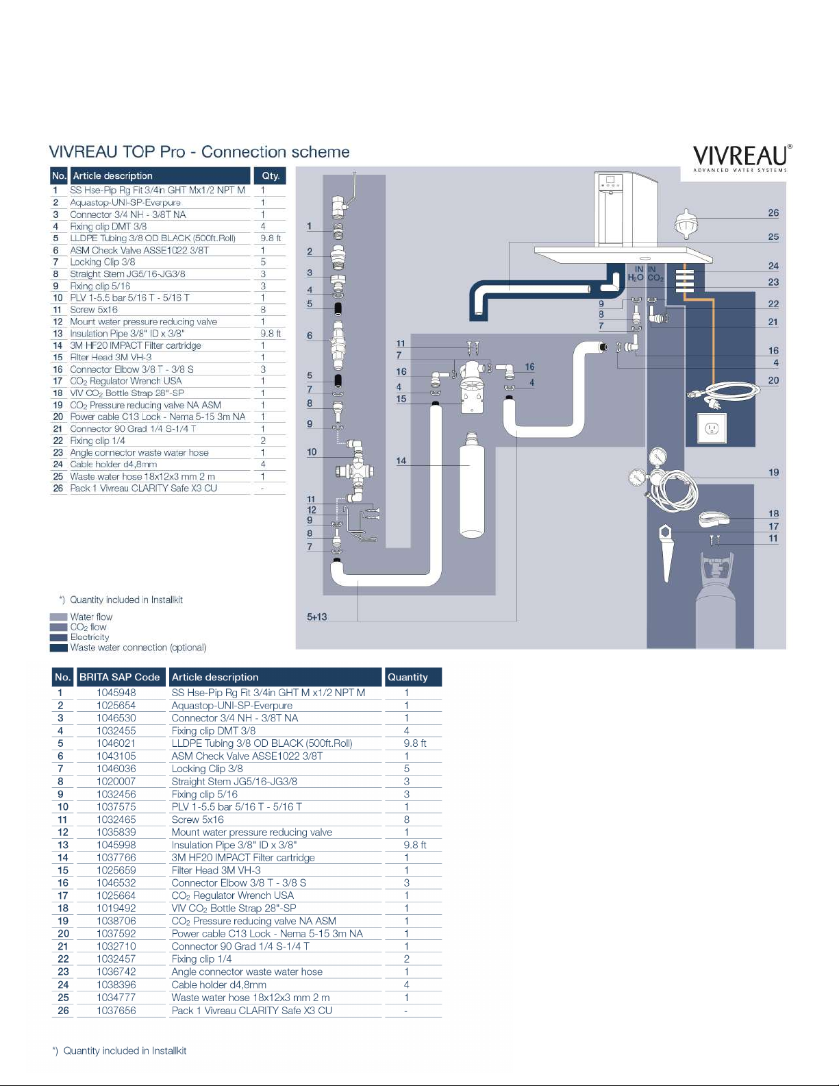
Step 3 — Water connection concept
• Make the connections at the customer water supply, water block and lter head.

Step 4 — Optional Drain to waste
• If the drip tray is connected to the drain hose, the blind plug must be removed. (see rst picture)
• To connect the hose to the drip tray, the water dispenser must be tilted slightly to the side. (see
second photo)
• Please note: The hose must be pulled without hose clamp, untreated and dry on the drip tray,
otherwise it will slide down again!
• Remove the foil from the drip tray grid. (third picture)
• Check whether the water is draining correctly from the drip tray
If no drain is available skip to step 6
Step 5 — Secure connections to the device
• Tilt the device to get to the connections below and to connect them.
• An angle is provided in the installkit. Otherwise, the device cannot be moved.
• At this point the screw feet should be removed and disgarded.
• If the device is mounted on the base cabinet, follow the instructions starting on page 18.
Step 6 — Open housing & leak check
• Open the housing (instructions below)*
• Check the device for possible leaks.
• No adjustments are made to the pump.
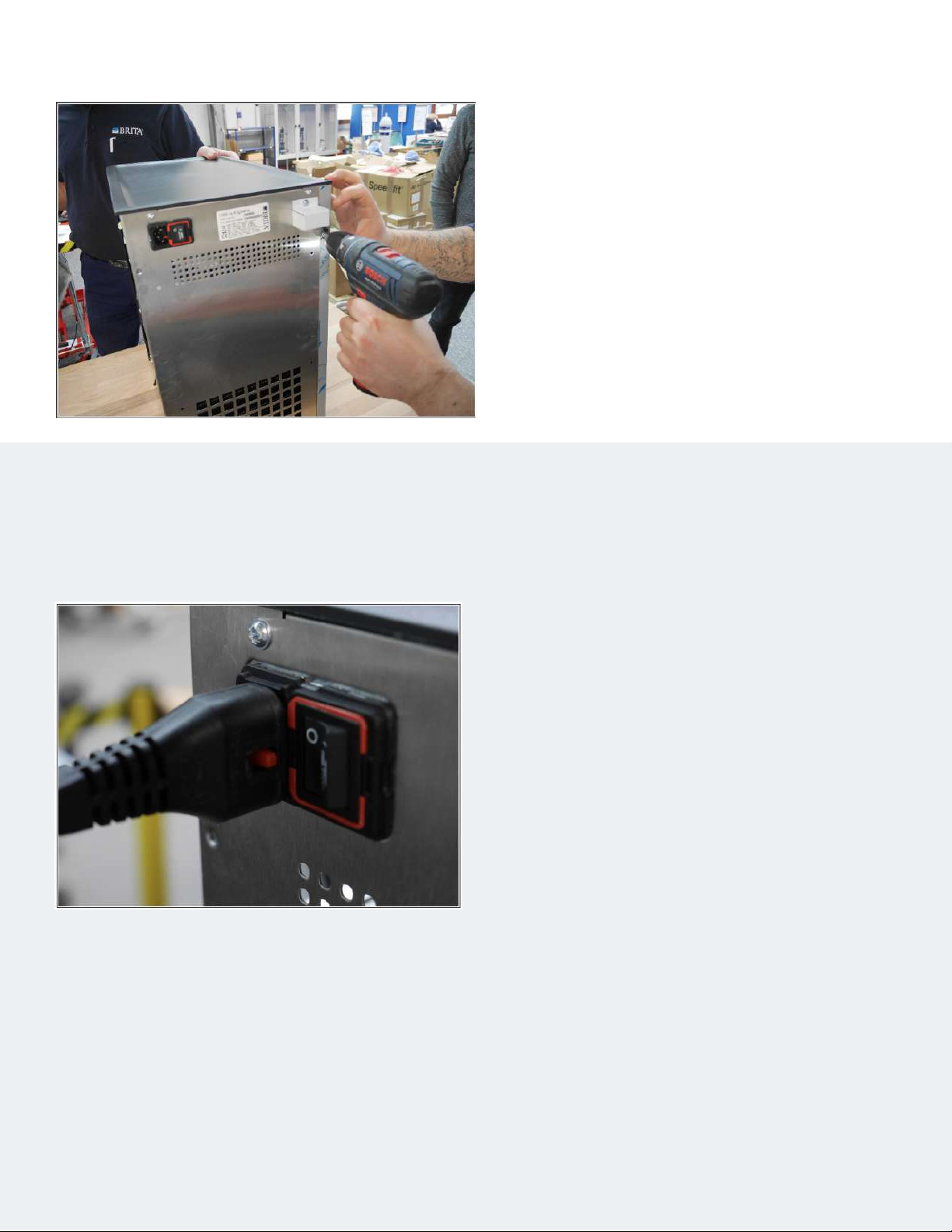
*Open / close the Top Pro housing Instructions
• Switch o the device using the power switch.
• First disconnect the power plug from the socket
and then from the device.
• To do this, push the red snap-in hooks (pull-out
protection) to the rear.
Step 1— Establish a stress-free state
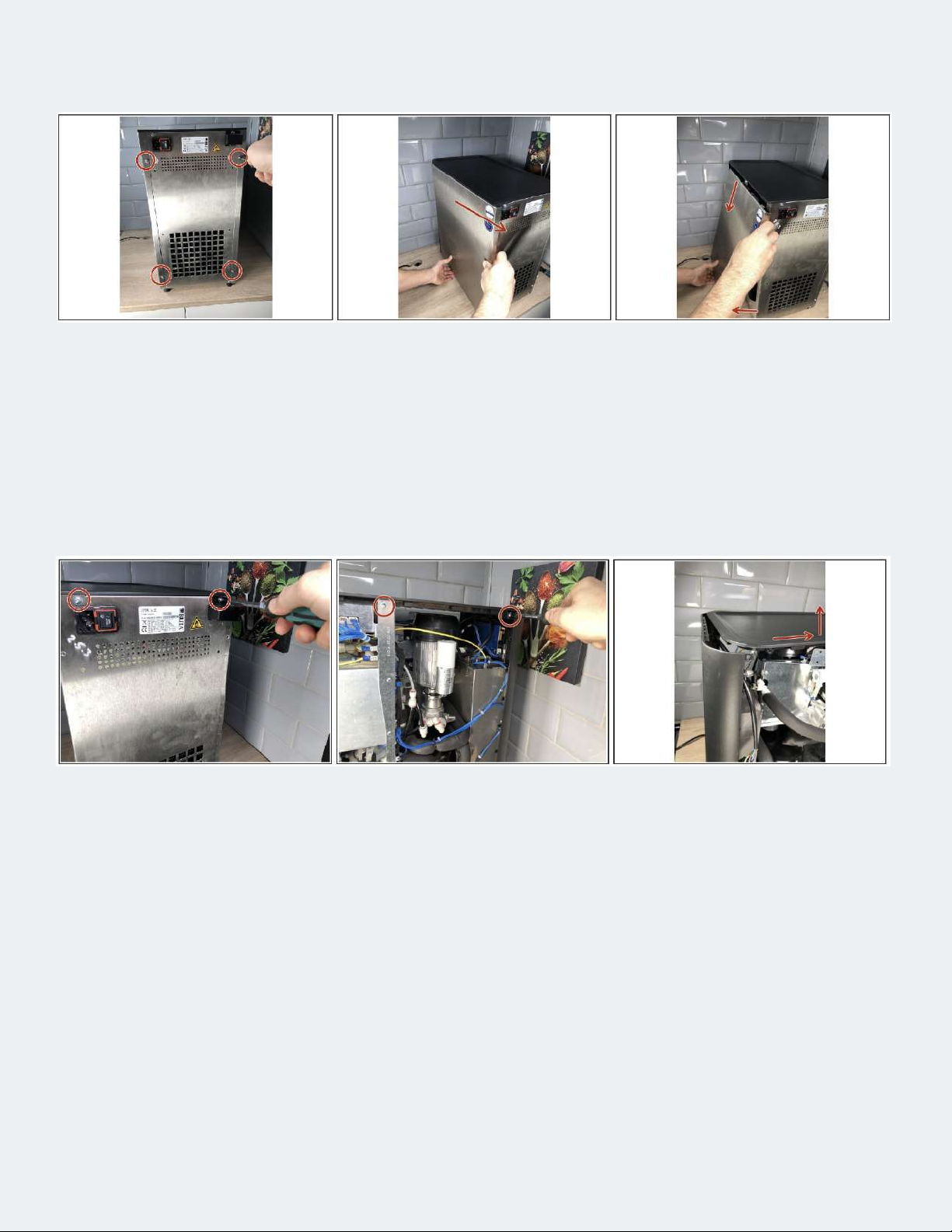
• Remove 2 screws on the back of each side panel (image 1).
• Pull the side wall backwards a little (picture 2).
• Pull the side panel away from the device at the bottom and then unhook it from the latches (image 3).
Step 2 — Remove sidewalls
• To remove the cover, both side parts must rst be removed.
• Loosen 6 screws (2 left, 2 right, 2 at the back, see pictures 1 and 2)
• Slightly lift the cover at the back and pull it backwards (image 3).
Step 3 — Loosen the cover
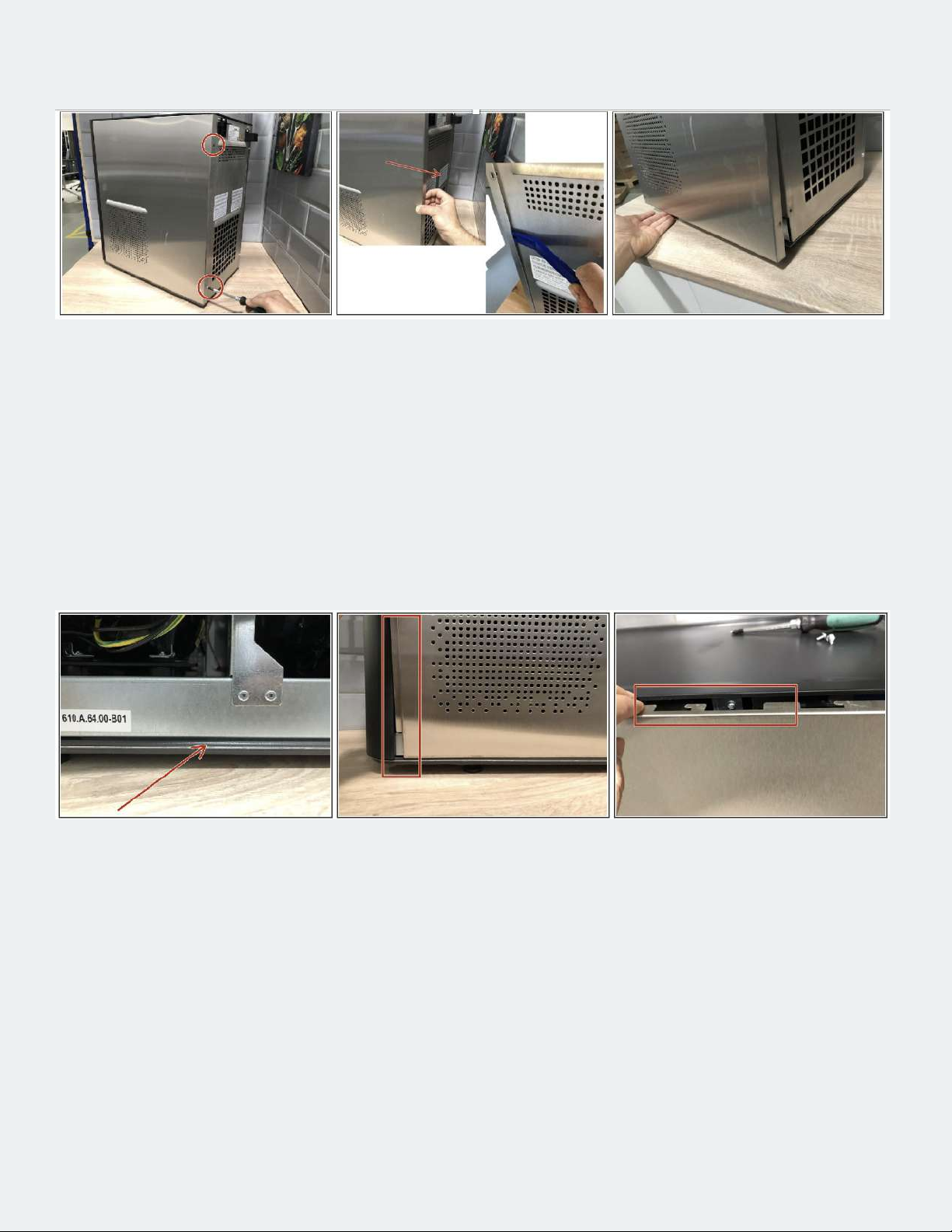
• Remove 2 screws on the back of each side panel (image 1).
• Pull the side wall backwards a little (picture 2).
• If necessary, use a plastic tire lever or something similar for this purpose.
• Pull the side panel out of the sealing lip at the bottom (image 3).
• Unhook the side panel downwards from the upper locking lugs.
Step 4 — Remove side panels
• First insert the side wall into the sealing lip below (Fig. 1).
• Position the side wall so that the sheet metal is ush with the front of the housing (image 2).
• Then hang the side panel on the snap-in hook at the top (image 3).
• Now slide the side panel forward and fasten it with screws at the back.
Step 5— Install side panels
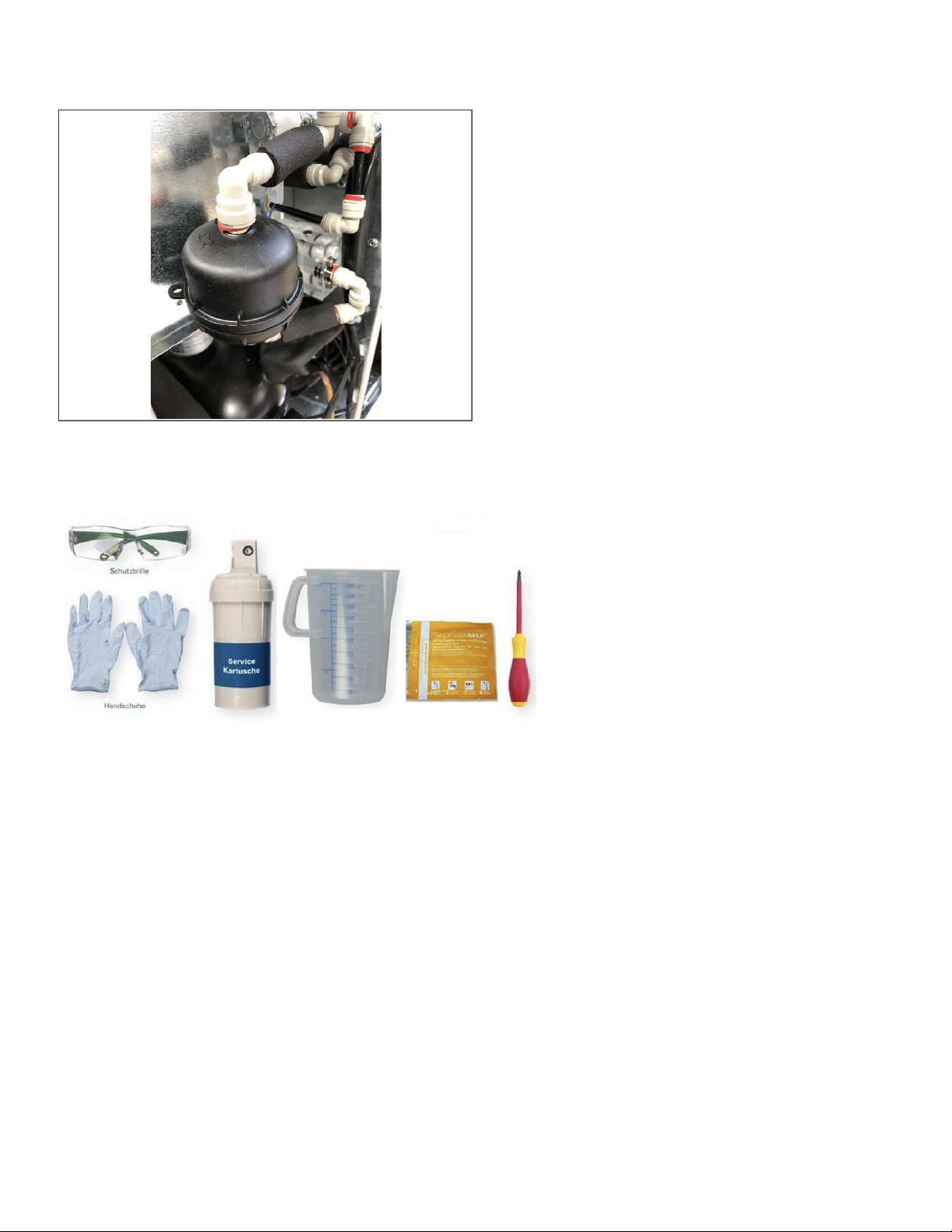
Step 7 — For devices with the Hygiene Plus option
• The SX3 hygiene lter is enclosed separately
on delivery. The point at which this is later
used is bridged with a piece of hose. The
SX3 lter is only used in the course of the
cleaning program (step 8)!
• On delivery, both connections of the lter are
closed with plugs. If these are missing, the
lter must not be used. The caps must be
removed before installation.
Step 8 — Chemical cleaning
• Carry out cleaning via the menu. Instructions outlined in the next 6 pages.
• During the exposure time, the drip tray can be removed and cleaned.
• In the course of rinsing after cleaning, the water ow can already be measured and adjusted using
the compensators (see next step).
• When rinsing, water is dispensed for 30 seconds; multiply this amount by a factor of 2.

Dry cleaning Top Pro & Extra I-Tap with
Iodophore USA Only or Huwa-San Canada Only
• During the entire cleaning process, it must be ensured that no drinking water is drawn o. If the
housing is open, the device must be protected against access. Caution! Danger to life in the event of
electric shock by touching live parts!
• Use appropriate safety gloves according to EN 374, safety glasses with side protection and suitable
work clothes.
• Attach the Do not Use sign.
• The device can not be operated with the Easy Access Panel in the cleaning program.
Step 1— Preparations
Step 2 — Start of the integrated cleaning program
• Open case; remove the right housing cover
• Start the cleaning program via the service menu. The following steps in these instructions contain
additional information or point out important points in the cleaning program.
• Enter the Admin mode on the front screen by entering the Service PIN: 0112
• Follow the instructions on the screen

Step 3 — only with Hygiene Plus: insert a new SX3 lter
• Not relevant for devices without the Hygiene Plus option.
• Insertion of the new SX3 lter. It is essential to wear clean gloves because a sterile lter. The
connectors are sprayed with alcohol-based disinfectant
• On delivery, both connections of the lter are closed with plugs. If these are missing, the lter must
not be used. The caps must be removed before installation.
Step 4 — only with Hygiene Plus: insert a new SX3 lter
• Check the expiry date of the cleaning agent. Expired cleaning agent must not be used.
• Put cleaning agent in the service cartridge.
• USAWhen using Iodophor add 2ml of the chemical to a 500ml service cartridge
• CanadaWhen using Huwa-San, add 80ml of the chemical to a 500ml service cartridge.
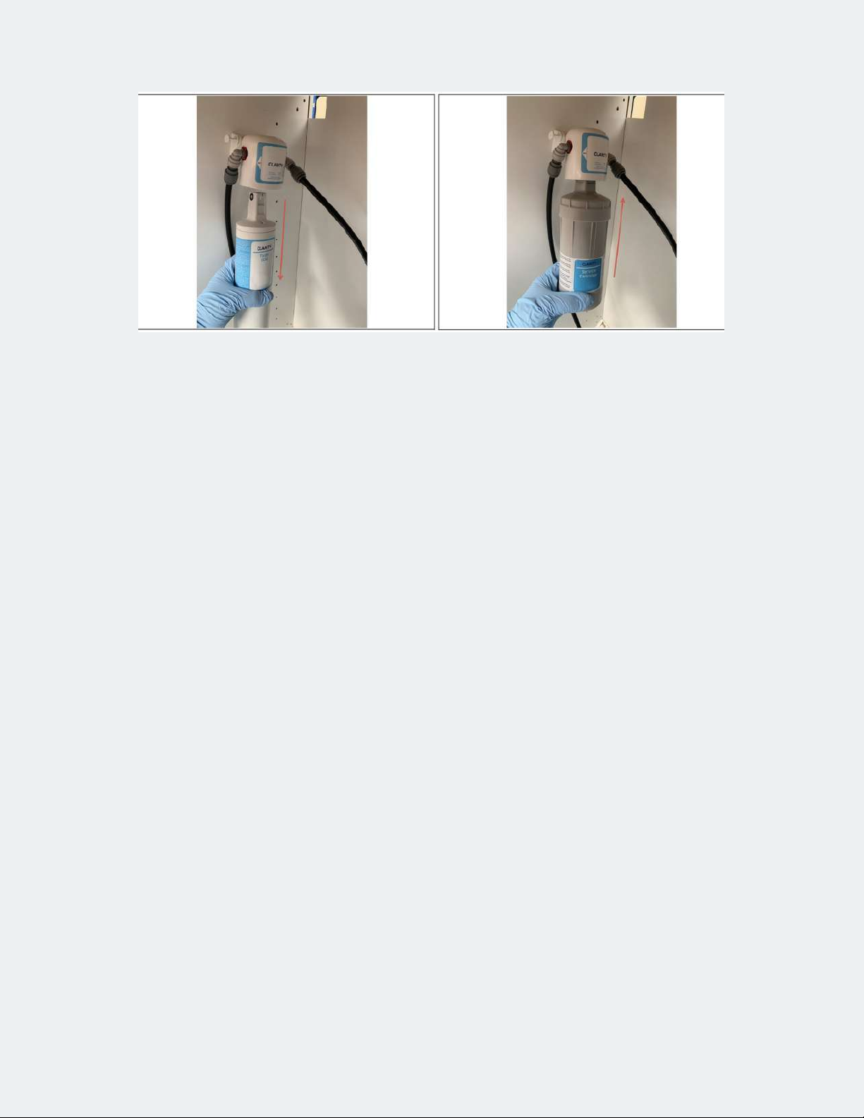
Step 5 — Service cartridge insert
• Cold water lter Pull cartridge out of lter head.
• Insert new input lter.
• Disconnect the line to the device and place it in a container / bucket.
• Open H2O and rinse the lter with water according to the manufacturer‘s instructions (Clarity button 1L).
• Close H2O. Reconnect the line to the device.
• Use service cartridge lled with cleaning agent.
• Open the water supply.

Step 6 — Rinse in detergent
• If the lling process of the carbonator cannot be completed due to high counter pressure, pull the
safety valve (Fig. 1). Use a cloth to absorb any splashing water.
• Draw o the respective types of water as specied by the cleaning program (rst still and still chilled,
then sparkling). End the dispensing process with Next.
• Draw 100 mL sparkling drinks and 50 mL still chilled and still unrefrigerated.
• The tapping process can be interrupted and continued at any time with Pause or Run.
• Put up the information sign. Now let the cleaning agent act for 10 minutes.
• During the entire cleaning process, it must be ensured that no drinking water is drawn o. If the
housing is open, the device must be protected against access. Caution! Danger to life in the event of
electric shock by touching live parts!
Step 7 — Empty the carbonator
• Open the CO2 supply line.
• Close the water supply.
• Tap the soda until only CO2 escapes.

Step 8 — Empty the carbonator
• Remove the service cartridge and insert a new pre-rinsed cold water lter cartridge.
• Open the water supply.
• Place a vessel under the outlet. The cleaning program carries out rinses for all types of water.
The carbonator is completely ooded (overpressure valve must be pulled).
• When rinsing, the water types are changed several times. Due to the short stagnation, residues
of the cleaning solution are released from dead corners.
• The cleaning program from rmware 2.2.9 species 2 rinsing cycles.
• Flush volume sparkling 10 L (2 x 5 L), chilled 5 L (2 x 2.5 L), still 5 L (2 x 2.5 L).
Step 9 — Rinse out cleaning agent
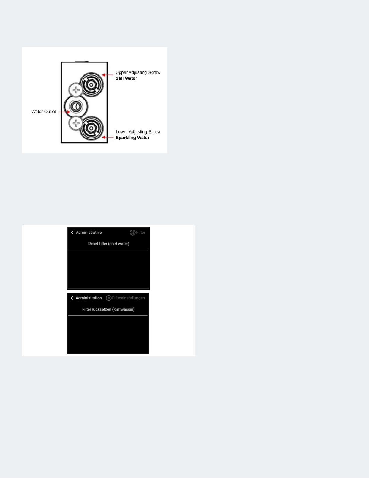
Step 10 — Set the ow pattern on the compensator if the ow is
too fast or too slow
• Set the ow diagram of the compensator.
Instructions starting on the next page.
• Close the housing.
Step 11 — Ensure operation
• Ensure trouble-free operation through
functional test.
• Reset lter capacity (menu Administration -
Filter - Reset lter (cold water), see gure 1.
• Clean the working environment, remove
the Maintenance sign.

• Set the CO2 pressure to 65 psi
• Draw o the sparkling water and measure the ow rate per minute. This must be less than 1.7 l / min.
If the ow rate is too high, turn the lower adjusting screw in slightly and measure the ow rate again.
Repeat this until the ow rate is between 1.6 and 1.7 l / min.
• If the value cannot be reached because the water inlet pressure is too low, the highest possible value
must be set and this must be taken into account in the subsequent setting.
• Draw o still (chilled or uncooled) water and measure the ow rate per minute. In principle, this
should be a little lower than with soda. Setpoint 1.5-1.6 l / min. Adjustment is made using the upper
adjusting screw.
• Draw o the medium water and check the visual appearance of the water. If the water appears milky,
screw in the upper adjusting screw slightly and check again.
• The jet pattern of the water jet can now be adjusted by slightly turning the needle valve (Fig. 2). To
adjust, loosen the lock nut and then tighten it again.
• If these settings do not lead to an optimal spray pattern, reset the compensator and needle valve to
the basic settings (see next step) and carry out the setting again as described above.
Step 1 — Setting ow diagram
Setting the Flow Diagram

• For the basic setting, close the compensator or needle valve completely (not too tight, slight
resistance can be felt) and open it again as follows:
• Compensator lower cone (sparkling water) for TG devices: 1.5 turns.
• Compensator lower cone (sparkling water) for Hygiene Plus devices: 2-2.25 turns.
• Upper cone compensator (still water): 1.0 turns
• Needle valve DMT Top Pro: 1.25 - 1.5 turns
• Needle valves from the manufacturer Römer (Fig. 1, included in production at the end of 2020) are
completely opened for the basic setting and then 4.5 turns closed for Top Pro. To ne-tune the
medium spray pattern, the Römer needle valve must then be opened slightly wider.
Step 2 — Basic settings
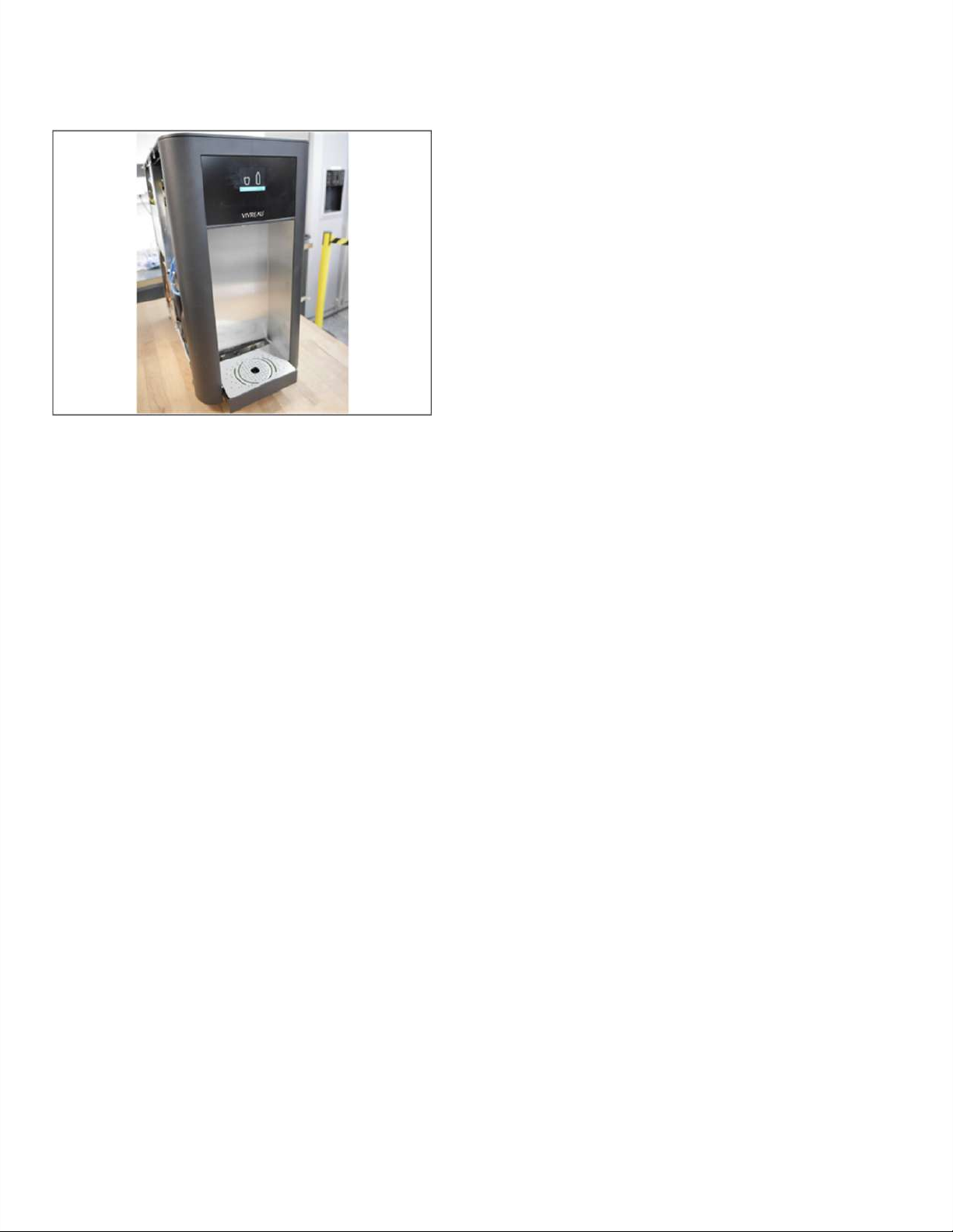
Step 9 — Completion of the installation
• Remove transparencies
• Adjust portioning with the customer
• Handover to the customer

Additional top installation
on base cabinet

• Unpack the base cabinet.
• Lift the box and pull it up and away.
• Open base cabinet with key.
• The key for the Base Cabinet is located on the device (image 1).
• Check that the assembly material is complete.
• Unpack the base plate (optional).
• Allocation of the fastening parts, see Figure 2.
• Check the Base Cabinet for transport damage.
Step 1 — Unpack and control
Number Description Used for
1 Washer 6.4x18.1.6 Wall bracket
2 Tube wall bracket Wall bracket
3 Dowel 8x52 mm Wall bracket
4Screw countersunk
head D6x160mm Wall bracket
5Screw cross recess
M6X50 Fixing unit to Base Cabinet
6 Screw M4X8 CO2 belt and clamp pressure
reducer
7 Hose clamp Mains cable to Base Cabinet
1 2
3
4 5
6
7
• Remove the assembly ap (upper section), see Figure
1.
• If necessary, the lower ap can also be removed, eg
for the drain (image 2).
Step 2 — Remove mounting ap
• Alternatively, the Base Cabinet can also be set up freely. The base plate must be used for this, see
step 4 of these instructions.
• In the photos, the assembly ap is still closed, it should be removed before assembly, see previous
work step!
• Place the Base Cabinet in front of the wall. The distance to the wall must be 10 cm.
• Mark drill holes. To do this, for example, insert the screws supplied straight through the holes in the
back wall of the Base Cabinet and then use the screw to mark the position of the drill hole on the wall
(image 1). Alternatively, mark the lower hole on the wall (distance from the oor 53.5 cm).
• Distance between drill holes horizontally 160 mm, vertically 110 mm
• Ensure that no power or water lines are drilled into. Drill 4 8 mm holes in the wall and insert dowels.
• Guide the screw 160 mm through the rear panel. First put on a disc, then spacer tube and then
another disc. Screw the base cabinet to the wall (image 2).
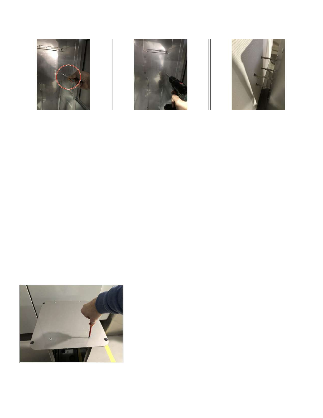
Step 3 — Fasten the Base Cabinet to the wall (optional)
switch order to have base plate 1st
• Turn bass cabinet over. Use a pad to avoid scratches.
• Remove the feet of the base cabinet (image 1).
• Place base plate on base cabinet.
• Align the longer side to the front (image 3). The side with
the countersunk drill holes is now facing up.
• Fasten the base plate with 4 screws (image 2).
• Turn the base cabinet over again.
Step 4 — Fixing the base plate
Table of contents
Other Vivreau Water System manuals


Popular Water System manuals by other brands

Kessel
Kessel Aqualift S 100 installation instructions

AquaSure
AquaSure Quantum Series owner's manual

Canature
Canature 785 HIMTLC PLUS Series owner's manual

Water Control
Water Control PS-5 Troubleshooting and maintenance guide

Imetec
Imetec TYPE H1701 Instructions for use

First Sales
First Sales XTS30 Installation instructions and owner's manual

Watts
Watts WQC4RO11-50 Installation, operation and maintenance manual

Mueller
Mueller HYDRO GUARD HG-11 Standard User's operation manual

Everpure
Everpure Exubera Pro UC EV9333-50 Specification sheet

Waters
Waters ACQUITY System guide

Aerus
Aerus Origins WC300 Operation manual

Sartorius
Sartorius arium mini plus operating instructions


