Viz-Art Automation CP-LIFT S User manual

LIST OF ITEMS:
Lift for TV;
TV bracket;
Mounting kit;
Installation manual
1. PREPARATIONS FOR MOUNTING:
(TRUST INSTALL WITH PROFESSIONAL AUDIO VIDEO INSTALLERS)
1. After removing the lift from the transport packaging, connect the lift to 230V power supply according to
the diagram - electrical connection (page 5, pict. 3).
2. Start the lift to open.
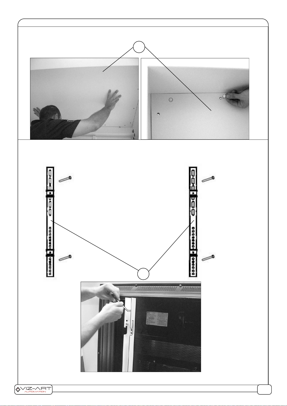
3. Remove the white plate from the lift (pict. 2B). Then, as shown in pict. 2E, tihgten the "K" screws. Then,
lifting up, remove the "H" plate.
4. Close the lift again and disconnect from power supply.
2. INSTALLARION AND ADJUSTMENT:
2A 1. Mark the CP-LIFT mounting location and drill 4 holes in the solid ceiling, and then place dowels inside
(The manufacturer provides standard dowels in the mounting kit. The selection of appropriate dowels and
screws for the type of ceiling at the installation is on the side of the installation team) .
2. Pass the lift bean holes (marked A) insert the bolts and tighten them to stable mounting the lift to the
ceiling.
CP-LIFT S
TV lift
A
1/6
2B. After mounting the lift to the ceiling, attach the white masking plate (marked B) by passing plastic
fastening rivets in the holes (in the assembly kit).
2C. Screw centrally the 2 elements of the TV mount into the TV (marked C). Make sure that in both
elements of the bracket are screws on the same level –symmetrically.
WARNING! The safety of users and equipment depends on the proper installation of the lift and TV.
Choose TV mounting screws according to TV manufacturer's recommendations.
B
C
2/6

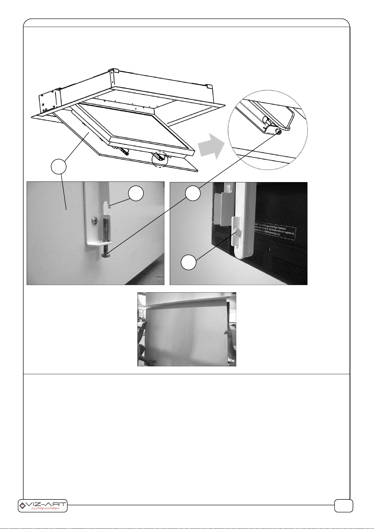
2D
1) To mount the TV, connect the lift to the power supply (according to the electrical connection diagram) and
tilt the movable lift arm so that it is vertically to the floor.
2) Place the TV set with the bracket to the movable lift arm (marked D) and center it so that the TV is in the
center of the arm (marked D).
3) Carefully closing the lift make sure that after closing the lift the TV is hidden symmetrically in the CP lift
housing protecting the TV (symmetrical TV spaced from the edge of the lift).
4) Tighten the counter screws (marked E) with an Allen key.
5) Pass the power and signal cables to the TV through the oval hole (marked F) in the CP-LIFT housing and fasten
them to the housing with a hose clamp, through the prepared "G" holes.
D
F
G
E
3/6
2E 1) Slide the white closing plate (marked H) in such a way that the 4 catches (marked I) slide on the studs
(marked J).
2) Tighten the screws (marked K) to lock the plate (marked H).
2F. SETTING THE OPENING AND CLOSING POSITIONS OF THE CP-LIFT –ONLY AFTER TV INSTALLATION:
OPENING THE LIFT - SETTING:
Attention! You can use the option of setting limit switches inside the lift (marked Open inside/Otwarty wew) or
outside the lift (marked Open outside/Otwarty zew). Adjust the settings to make minimal rotation, about 1/4
turn.
1. Open the lift to the desired position and adjust the limit switch (Open inside/Otwarty wew or Open
outside/Open zew) to the comfortable position of the TV. (If you use outside limit switches use a 8 mm socket
wrench. If you use inside limit switches use an Allen wrench 4).
2. By turning the key in the "+" direction you increase the lift opening angle (max 100 °), by turning in the "-"
direction you decrease the lift opening angle.
LIFT CLOSING - SETTING:
Attention! You can use the option of setting limit switches inside the lift (marked Closed inside/Zamknięty wew)
or outside the lift (marked Closed outside/Zamknięty zew).
J
H
I
K
4/6

1. Close the lift and adjust with the limit switch marked Closed inside/Zamknięty wew or marked Closed
outside/Zamknięty zew. Closes the lift.
2. Turning towards "+" closes the lift, turning towards "-" you open it.
Manufacturer: VIZ-ART Automation
tel.+48 22/6138899 www.viz-art.eu
5/6
Rules of safe operation of VIZ-ART AUTOMATION equipment.
SAFETY INFORMATION CAUTION
To ensure safety of the personnel, make sure to follow the guidelines provided in this instruction manual. Keep the instruction manual for future reference.
•Do not allow children to play with the device controller (switch or remote control).
•Do not leave device controllers within the reach of children.
•Inspect the equipment assembly periodically to identify and repair any damages.
•If any damages are identified, do not use the equipment until the necessary repairs are made.
•Keep appropriate distance from the equipment during operation. In case of a failure, the equipment may constitute a risk of injury or wounds.
•Do not install any items other than those specified in the equipment instruction manual. All installation and mounting works should be done by an engineer with
appropriate licenses.
•Inappropriate mounting may damage the product or cause injury.
•Use only elements compliant with the mounting instructions.
•It is prohibited to perform any steps that may damage the power supply cord or plug.
•Do not modify the power cord, i.e. do not make any structural modifications, do not place the cord in immediate vicinity of hot objects, do not bend or twist the cord, do
not pull the cord, do not place any heavy objects on the cord, and do not coil the power cord.
•Using the equipment with a damaged power cord may cause electrocution or shorting of the circuits and fire.
•Do not touch the power cord or plug with wet hands.
•Always follow the guidelines provided in this instruction manual and in the equipment mounting instructions.
•Before installing the equipment, make sure it is complete, free of defects, compliant with your order, and has not sustained damage in transport.
INSTALLATION GUIDELINES
•The equipment should be installed by a qualified engineer, in accordance with the guidelines provided in the mounting instructions. Electrical connections should be
made by a specialist with an appropriate license.
•Install the equipment using screws and mounting elements appropriate for the conditions of the installation, to which the lift is mounted, and stable, original auxiliary
elements, dedicated for the specific lift model.
•After mounting the equipment, before first use, check if it is mounted as per the instructions, and level. If the equipment is not level, adjust the mounting. Do not use
equipment that is not properly installed.
•Do not modify or unscrew elements of the equipment, as this may cause a risk of permanent damage to the equipment and/or the safety of the users.
WARRANTY CONDITIONS
The warranty period for the device is 24 months from the date of purchase indicated on the original receipt.
1) The warranty period for the device's electric drive is 60 months.
2) The warrantor commits to fix free of charge damage suffered by a device delivered to the service point that demonstrates defects resulting from defects in workmanship
or materials, which become noticeable during the warranty period.
3) The warranty does not cover:
a) damage caused by use of the device in a manner other than that described in the user manual,
b) damage caused by improper storage or transport,
c) mechanical damage,
d) abrupt changes in electrical grid voltage,
e) disassembly and reassembly,
4) Defects will be removed within 14 days from the date the device is ac-cepted on warranty at a service point.
5) Service point address
Manufactured after 13.08.2005.
Do not dispose of used electrical and electronic equipment together with municipal waste, due to the presence of substances hazardous to the environment in
the equipment. Such devices should be delivered to a collection point for recycling. Information on collection points is available from local government
authorities or in stores.
DECLARATION OF CONFORMITY
VIZ-ART AUTOMATION
I hereby declare, with sole responsibility, that the products:
Lifts: V-LIFT VESA; VMAX - LIFT 95; CP-LIFT S; CP-LIFT M; CP-LIFT L;
ART-LIFT; SIDE LIFT 65; SIDE-LIFT Pro; SMARTBOARD LIFT;
ADVANCED LCD Lift 17; ADVANCED LCD Lift 19; ADVANCED LCD Lift 24
to which this declaration relates, in accordance with:
the Low Voltage Directive 73/23EEC together with the modifications of Directive 93/68/EEC
EMC Directive 89/336/EEC along with its amendments92/31/EEC, 93/68/EEC i 91/263/EEC
comply with the following European standards:
EN 60335-2-97 with reference to EN 60335-1
EN 55014-1, EN 55014-2, EN 61000-3-2, EN 61000-3-3
and are CE certified.
Edycja 2.0 6/6
Table of contents
Other Viz-Art Automation TV Mount manuals


Popular TV Mount manuals by other brands


Multibrackets
Multibrackets M Flexarm Pro Extenderkit 600x900 installation manual

Sanus Systems
Sanus Systems VisionMount VMDD26 instruction manual

Kensington
Kensington SmartFit quick start guide

Novus
Novus NVB-5020JB user manual

Catalyst
Catalyst 63607151 Instruction booklet

Philips
Philips SQM6175/93 Guide


