4
Grommet Method
This method can be used for work surfaces that have a grommet hole in an
appropriate position. Surface thickness must be between 0.6" (15mm) and
1.5" (38.1mm), and the grommet hole diameter must be between 0.78" (20mm)
and 2" (51mm).
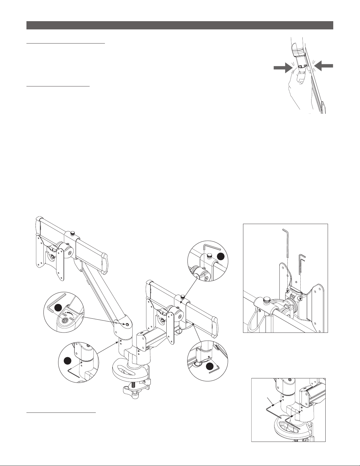
Remove Clamp Assembly
• Remove the standard clamp assembly from the
base assembly. Use the 4mm Allen key to remove
the three screws holding the clamp assembly in
position. Retain the three screws.
Attach Grommet Assembly
• Place the grommet bolt in the large center hole on
the grommet mount plate.
• With the grommet bolt in position, fasten the
grommet mount plate and bolt to the monitor arm
base with the three screws previously removed. As
before, use the 4mm Allen key.
Attach Clamp Pad
• Peel the backing from the adhesive side of the clamp pad and adhere the
pad to the bottom of the grommet mount plate, as shown. The pad protects
the work surface.
Install Base Assembly
• Place the base assembly over the grommet hole, with the bolt centered.
• The bolt must extend under the work surface a minimum of 1.3" (33mm).
• Secure the base assembly as illustrated.
— Secure the grommet bar and washer with one of the grommet bolt nuts.
Use the provided wrench to tighten the nut securely.
—
assembly.
• Proceed to “Install Monitor Arms” on page 5.
0.6" – 1.5"
(15mm – 38.1mm)
Remove
Clamp
Assembly
Attach
Grommet
Assembly
Adhere
Base
Assembly
Grommet
Bar
Washer
Nuts Wrench
EDGE2-MS DUAL MONITOR ARM INSTALLATION OF BASE ASSEMBLY