ViziT BUD-420M User manual

BUD 420
BUD 420
PARTS LIST
SAFETY INSTRUCTIONS
WARNING 3 V
-М
-М
VIZIT
200
!20
Control Unit the Control Unit hereinafter) is a part of multi-apartment doorphones and video doorphones
, and provides duplex intercom and remote entrance door unlocking.
The Control Unit enables connection of up to subscribers (apartments)
The Control Unit contains dangerous for life high voltage
Unplug the unit before replacing fuses and connecting wires. To avoid damage or electric shock do not make any repair
when the power is on.
The mains plug shall remain readily operable.
No metallic objects shall penetrate into ventilation openings of the unit. The unit shall not be exposed to dripping or
splashing, and no objects filled with liquids shall be placed on the unit.
(
.
.
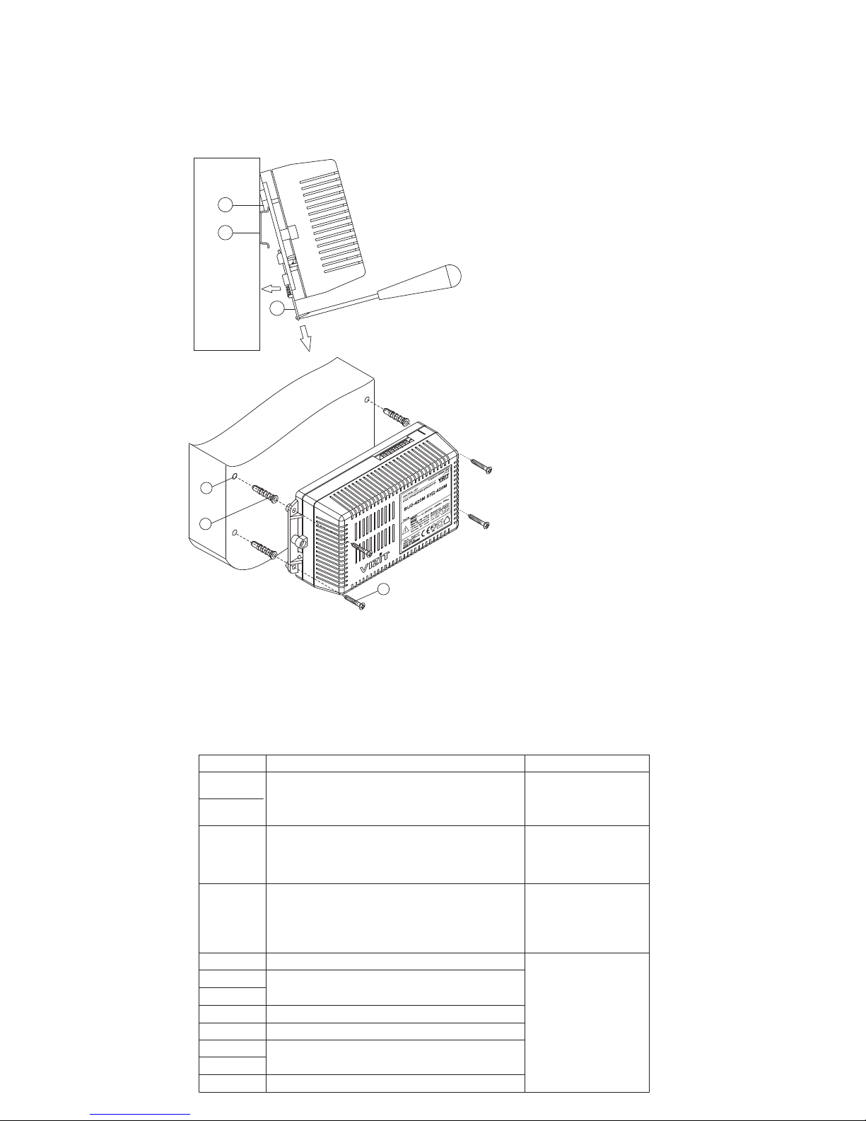
Control Unit’s Appearance
11
2345
6
1. Openings for screws
2. Mains cord
3. Mains switch
4. Holder for fixing the Control Unit on a DIN-rail
5. Terminals to connect to doorstation and lock
6. Terminals to connect to intercom line
Control Unit BUD-420M
Screw 3.5x40 Concrete Insert 46х 0
x4 x4
Operating Instruction
x1
FastenersFuses
x1
T200mAL
х1
TAL1
x1
1

DOORPHONE VIDEO DOORPHONE COMPONENTS
BVD
xxx
RVS RVS
VIZIT-M UKP
BK 4MV BK M BK BK M BK M
VIZIT-PK
DOORPHONE / VIDEO DOORPHONE FEATURES
1
/
VIZIT
400
VIZIT-ML400 VIZIT-ML300 VIZIT-ML240
"EXIT 301", "EXIT 300М"
-4, -2
400
- -4 -10 -30 -100
200
VIZIT
80
*
*
17
1200
6
VIZIT
*
*
*
*
VIZIT-TU412M1
Note . Only VIZIT-RF2 keys (PROXIMITY, 125 kHz) from VIZIT are supported.
Note 2.
KEY/CODE BUD-420M
BUD-420M
The Control Unit is compatible with the following products
doorstations / video doorstations of Series
electromagnetic locks
electromechanical locks with impedance no less than 10 Ohms;
buttons for exit
distribution amplifiers
video monitors of Series and/or apartment handsets ;
commutators ;
Concierge Console
All listed devices are available upon request. Parts lists and specifications for every product are given in its
operating instruction.
by pressing the
(keys hereinafter)
by pressing the indoor button for exit
Intercom Concierge visitor concierge initiated
Intercom “Concierge - visitor” is described in detail in the operating instruction on ontrol nit
®
®
®
:
-();
,,;
-
;
-;
-
-,,,,
-.
Calls to subscribers by dialing their apartment number
Duplex intercom (up to seconds)
Entrance door unlocking:
- button on the apartment handset / monitor during intercom
- by applying RF-keys or TM-keys DS1990A/iButton
- by dialing a 4-digit general access code
- by dialing a 3-digit individual access code
-
Programmable unlocked state duration ( or seconds)
Key memorizing by a continuous register (up to keys) or by the apartment list
(clusters of up to keys per apartment)
Key erasing (lost keys)
Individual access codes memorizing
Enabling / disabling calls to a selected apartment (individual access code remains active)
Team work of up to 4 Control Units (control unit plus doorstation)
Team work with Concierge Console
“-” **
Beeps to indicate operating modes of doorphone / video doorphone
LED indication of operating modes, or messages on the doorstation’s LCD (depending on a doorstation model)
English or Russian MENU and messages on the doorstation’s LCD during programming
Ring sound in the apartment handset / monitor and beeps in the doorstation when calling
Beep volume adjustment for the doorstation
Beep in the apartment handset / monitor, when its key or individual access code is used
4-digit apartment numbering (HOTEL mode)
Programming new individual access codes by subscribers
Key memorizing and erasing by subscribers
This function can be enabled or disabled during programming.
** C U for
concierge console.
General and individual access codes and keys are memorized in the memory chip, which is set in the socket
on the Control Unit’s PCB. The Control Unit supports memory chips from other control units
. When inserting a compatible memory chip into the chip socket, all stored keys and access codes are
recognized and supported.
-
-
·
·
·
·
·
·
·
·
·
·
·
·
·
·
·
·
·
·
·
·
2

GUIDE FOR SELECTING
DOORPHONE / VIDEO DOORPHONE COMPONENTS
Control Unit
BUD
Doorstation
Lock
.
MV M
MV M
BK BK
MV M
MV
MV
Concierge Console
PK PK
-420М 200
VIZIT
VIZIT-МL240х VIZIT-МL300х VIZIT-МL400x
Do not use electromagnetic locks with impedance less than 20 Ohms and not provided with a built-in
degaussing module.
Do not use electromechanical locks with impedance less than 10 Ohms
Button for exit
"ЕХIT 301" "ЕХIT 300М"
Commutators and distribution amplifiers
BK-4 BK-4 BK-10 BK -30М BK -100М
BK-4 BK-4 4 BK-10 10 BK-30М 30 BK -100М
100
BK-4М BK-10 BK-30М BK-100М RVS-4
(RVS-2) RVS-4 4
RVS-2 2
BK-4МV -4М RVS-4 -4МV
BUD-420M
BK-4 BK-4 50 BK-10 20 BK-30М 7 BK -100М 2 , RVS-4, RVS-2
50
Note.
BK-4 RVS-4, RVS-2 25
BK-4 RVS-4, RVS-2 26
BPD18/12-1-1 19W/14.4V/EU(18V,1A)
Subscriber Devices
BUD-420M VIZIT-M UKP-7 UKP-12
UKP-12M UKP-12-1
VIZIT- 200 VIZIT- 800
.
Electromagnetic locks , , with a built-in degaussing module are
recommended.
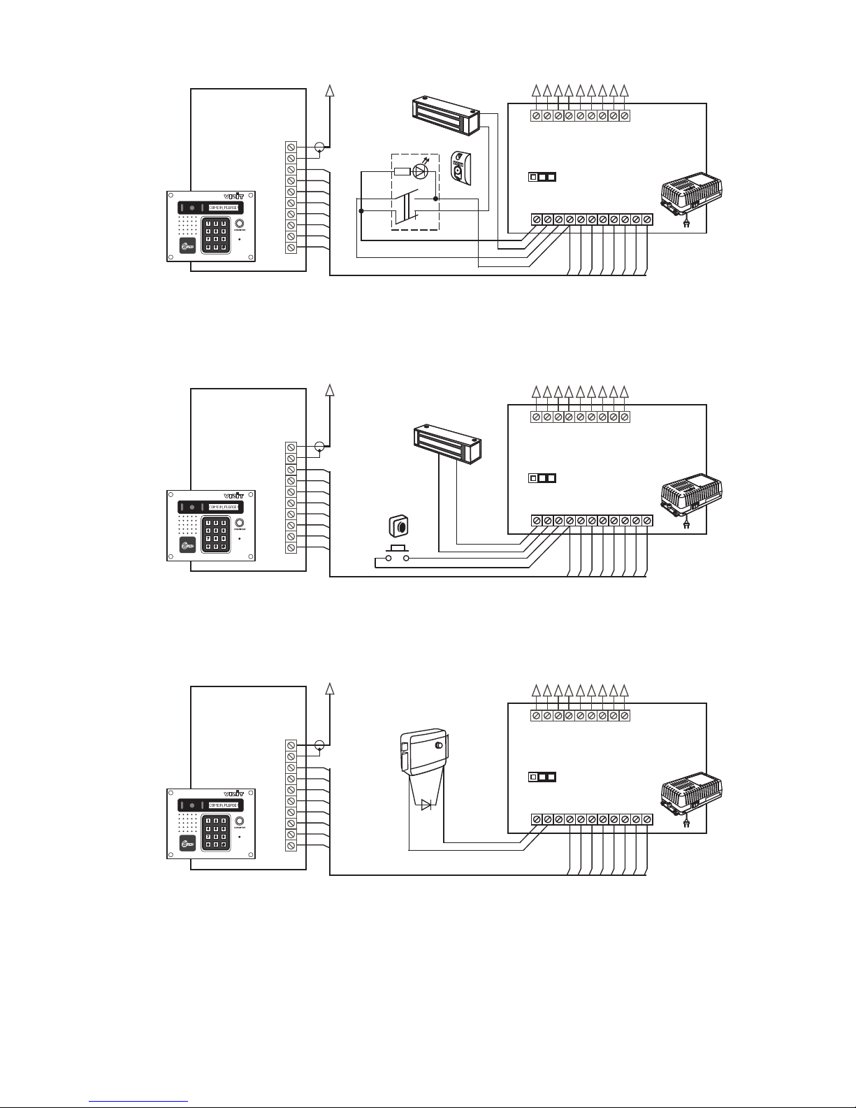
An electromechanical lock with impedance 10 Ohms may be used as well. A damper diode (50V/1A) should
be connected to electromechanical lock's terminals (not supplied).
The Button is recommended to unlock the door from inside of the building. It controls an
electromagnetic lock and ensures emergency lock release.
Commutators provide connection of subscriber devices (monitors and handsets) to the video / intercom line.
odel and number of commutators to be used depend on number of subscribers and type of subscriber devices.
Adoorphone / video doorphone may include such commutators as , , , .
Commutators , – , – ,
–.
Where a video doorphone uses commutators , , , , the distribution amplifiers
shall be applied to provide video signal from the doorstation to monitors.One is able to connect up to
monitors. One can connect up to monitors.
Commutator integrates features of commutator and distribution amplifier . is a preferred
choice for application in muli-apartment video doorphones.
acceptable number of commutators and distribution amplifiers to connect to the Control Unit (200
subscribers at most):
-upto , –upto , –upto , –up
-upto .
If the total number of applied in a video doorphone is units or less, they are powered from the
Control Unit. If the number of applied is units or more, an additional power supply unit
or shall be used to supply power to the commutators and distribution amplifiers.
Various combinations of the listed commutators and distribution amplifiers are possible to be used in a single doorphone /
video doorphone.
The Control Unit supports video monitors of Series 400, and apartment handsets , ,
,.
Adoorphone / video doorphone can be completed both with video monitors and apartment handsets.
.
provides connection of up to subscribers
Control Unit BUD-402M operates together with doorstations of Series 400.
no less than
the
or
Particular
m s the the
,
, connect up to subscriber devices up to up to
up to devices
The
, units units units units
units
,
,
Concierge Consoles and are supported
®
3
INSTALLATION
VIZIT
WARNING! Do not mount the unit near heating equipment!
CONNECTIONS
1
The Control Unit should be installed in heated premises with sufficient ventilation, and securely fixed to a wall, or inside
the Mounting Box . Terminals should be oriented horizontally. Such conditions provide proper ventilation of the unit.
The unit can be fixed by means of either a DIN-rail or screws
Installation of other doorphone / video doorphone components is performed following their operating instructions
Doorphone / video doorphone units are connected to the Control Unit via terminals on its PCB.
To perform connections, remove the lid from the Control Unit. Terminals names and destinations to connect a
doorstation, button “EXIT ” “EXIT ”) and lock are given below in Table .
Table
.
.
301 ( 300М
1.
1
2
3
1
2
3
1
2
3
-
-DI -
-
Bosses on the Control Unit’s base
rail, (W) = 35mm, (D) = 1-2mm
Holder for fixing
N
Mounting on a DIN-rail
1x4
2x4
3x4
4
–()
6
0
–()
–()
–
Hole
diameter = mm
depth = 4 mm
Concrete insert
Screw
Control Unit
Mounting on a wall
Terminal Destination Address
Door lock control
To door lock
and button
“"
"")
EXIT 301
( EXIT 300М
+DL
-DL
ОР OPEN
SP+ Speaker
To doorstation
SP-
MIC Microphone
+Е Supply voltage for doorstation
DSD Doorstation data
TX Control Unit data
GND Ground
TM Key reader
RX
To button
“"
"")
EXIT 301
( EXIT 300М
To doorstation
and button
“"
"")
EXIT 301
( EXIT 300М
4
Terminals names and destinations to connect the Control Unit to the intercom line are given in Table .
Table
Use copper wires for connections with regard to the acceptable cross-sections and lengths shown in Table .
Table
Control Unit
doorstation commutator, - apartment handset
The Control Unit is connected to the mains by means of its mains cord
Wiring diagrams are shown in the section
To ensure proper operation of the doorstation built-in key reader, total capacitance of the circuit (Fig. 1-3) with
respect to the rest of the wires in the cable connecting the Control Unit and doorstation must not exceed 1500 pF.
ial
Correspondingly the terminal of the commutator connecting
their
2
3
Note. BUD BUD 420
BVD BK UKP
“EXAMPLES OF WIRING DIAGRAMS”
Connection of doorstation door lock and button for exit
TM
Connection of commutators and concierge console
odd 1 3 1 1
2.
3.
–,
–,– .
.
Examples of wiring diagrams of the Control Unit and various doorstations, door locks and buttons for exit
are given on Fig. 1-3.
Use a 75-Ohm coax cable for video line between the doorstation and commutators. To avoid image distortion connect
an resistor between the and terminals of that commutator or distribution amplifier , which
goes last in the video circuit (see Fig. 4).
Examples of wiring diagrams of the Control Unit and various commutators, distribution amplifiers and
concierge console are given on Fig. 4-11.
The terminal of the commutator connecting apartment handsets / monitors from apartments with
numbers (e.g., apartments No , ), shall be wired to the circuit connected to the terminal of the
, apartment handsets / monitors from apartments with
numbers (e.g., apartments No , ), shall be wired to the circuit connected to the terminal
of the
If the total number of subscribers in a doorphone / video doorphone is , the terminals and of
shall be shorted.
Programming of commutators and connection of subscriber devices are given in operating instructions.
*-М
,.
BUD-420M
82-Ohms VO VG BK-4MV RVS-4
BUD-420M
SEL even hundred
085 285 SEL0 SEL0
BUD-420M.
SEL
hundred 85 85 SEL SEL
BUD-420M.
100 or less SEL0 SEL1
BUD-420M
Terminal Destination Address
LINE Intercom line
GND Ground
Ek Supply voltage and address for commutators
SEL0 Selection of commutator
SEL1
To commutators
Circuit Maximal length, m
75 200 300
-1030
-3050
Wire Cross-section, mm2007.02.05.
Diameter, mm 0 3.05.08.
10 20 50
BUD - BVD*
BUD - BK - UKP / Monitor
BUD - R 10 OhmsElectromechanical lock ( )
BUD VIZIT-ML400- Electromagnetic lock
5
12
3
8 7 6 54
12
3
8 7 6 54
12
3
8 7 6 54
Doorstation
-431DXKCB
( -432RCB)
BVD
BVD
8
7
6
5
4
3
2
1
VO
VG
TM
SP+
SP-
MIC
GND
+E
DSD
CUD
8
7
6
5
4
3
2
1
VO
VG
TM
SP+
SP-
MIC
GND
+E
DSD
CUD
8
7
6
5
4
3
2
1
VO
VG
TM
SP+
SP-
MIC
GND
+E
DSD
CUD
50 V
1A
LINE
GND
SEL1
Ek
USE
Evk
GND
GND
SEL0
+DL
-DL
OP
TM
SP+
SP-
MIC
GND
+E
DSD
CUD
MLEL
LOCK
LINE
GND
SEL1
Ek
USE
Evk
GND
GND
SEL0
+DL
-DL
OP
TM
SP+
SP-
MIC
GND
+E
DSD
CUD
MLEL
LOCK
LINE
GND
SEL1
Ek
USE
Evk
GND
GND
SEL0
+DL
-DL
OP
TM
SP+
SP-
MIC
GND
+E
DSD
CUD
MLEL
LOCK
Electromagnetic
lock VIZIT-ML400
Button
EXIT 300М
Red
Green
Blue
White
Black
To commutators
Control Unit
BUD-420M
Figure 1 - Control Unit
and button
BUD-420M BVD-431DXKCB( -432RCB)
VIZIT-ML400 “EXIT 300М”
with doorstation ,
electromagnetic lock
BVD
Electromagnetic
lock VIZIT-ML400
To commutators
Control Unit
BUD-420M
Button
for exit
Figure 2 - Control Unit
and button for exit
BUD-420M BVD-431DXKCB( -432RCB)
VIZIT-ML400
with doorstation ,
electromagnetic lock
BVD
E
LECTROMECHANICAL
LOCK
,)(12V 1A
To commutators
Control Unit
BUD-420M
Figure 3 - Control Unit BUD-420M
BVD-431DXKCB( -432RCB)
with doorstation
and electromechanical lockBVD
To commutators
To commutators
To commutators
Doorstation
-431DXKCB
( -432RCB)
BVD
BVD
Doorstation
-431DXKCB
( -432RCB)
BVD
BVD
EXAMPLES OF WIRING DIAGRAMS
6

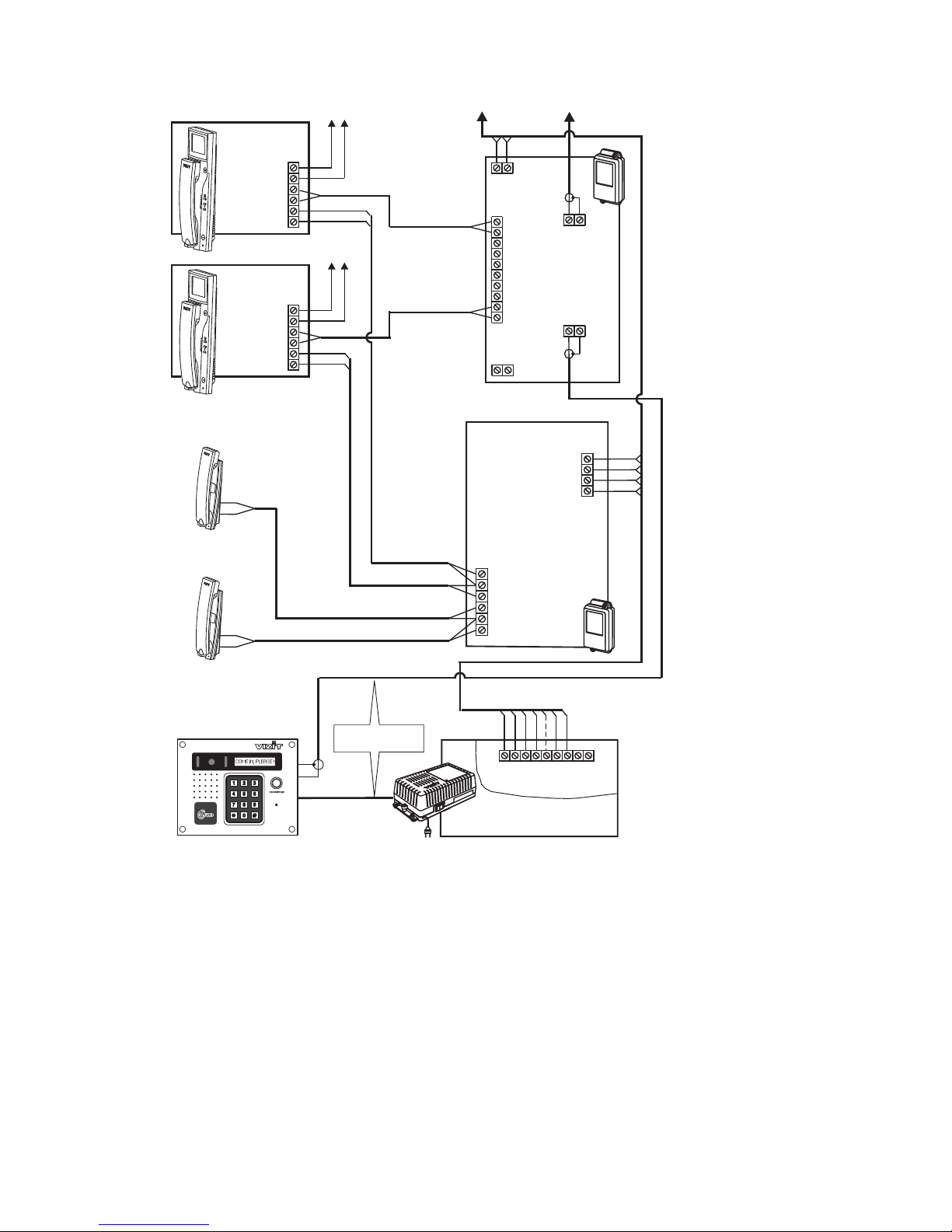
Figure Control Unit with monitor
and commutator in a video doorphone for subscribers
4- BUD
MV
-420М VIZIT-M430С
-4 200BK
Power Supply Unit
-18V
+18V
V1
FA
LN
VG
V2
FB
LN
VG
V3
FC
LN
VG
GND
LINE
SEL
Ek
VI
VG
VG
V4
FD
LN
VG
VO
123
46
7
-Ohms resistor shall be connected between
in the circuit
VO
VG -4MV
82
and terminals of the last BK
To monitors in apartments
LN-
GND
LN+
VI1
+E
DATA
Ec1
Ec2
GND
VI2
VIZIT-M430C
Monitor
Power Supply Unit
Commutator
-VBK M
-18V
+18V
V1
FA
LN
VG
V2
FB
LN
VG
V3
FC
LN
VG
GND
LINE
SEL
Ek
VI
VG
VG
V4
FD
LN
VG
VO
To monitors in apartments
LN-
GND
LN+
VI1
+E
DATA
Ec1
Ec2
GND
VI2
VIZIT-M430C
Monitor
82
LINE
GND
SEL1
Ek
USE
Evk
GND
GND
SEL0
123467
123
5
6
7
!
!
5
See Fig.1-3
Control Unit
BUD-420M
Doorstation
-431DXKCB
( -432RCB)
BVD
BVD
(To apartments
with
hundred)
odd
(To apartments
with
hundred
even
)
-V
Commutator
BK M
7
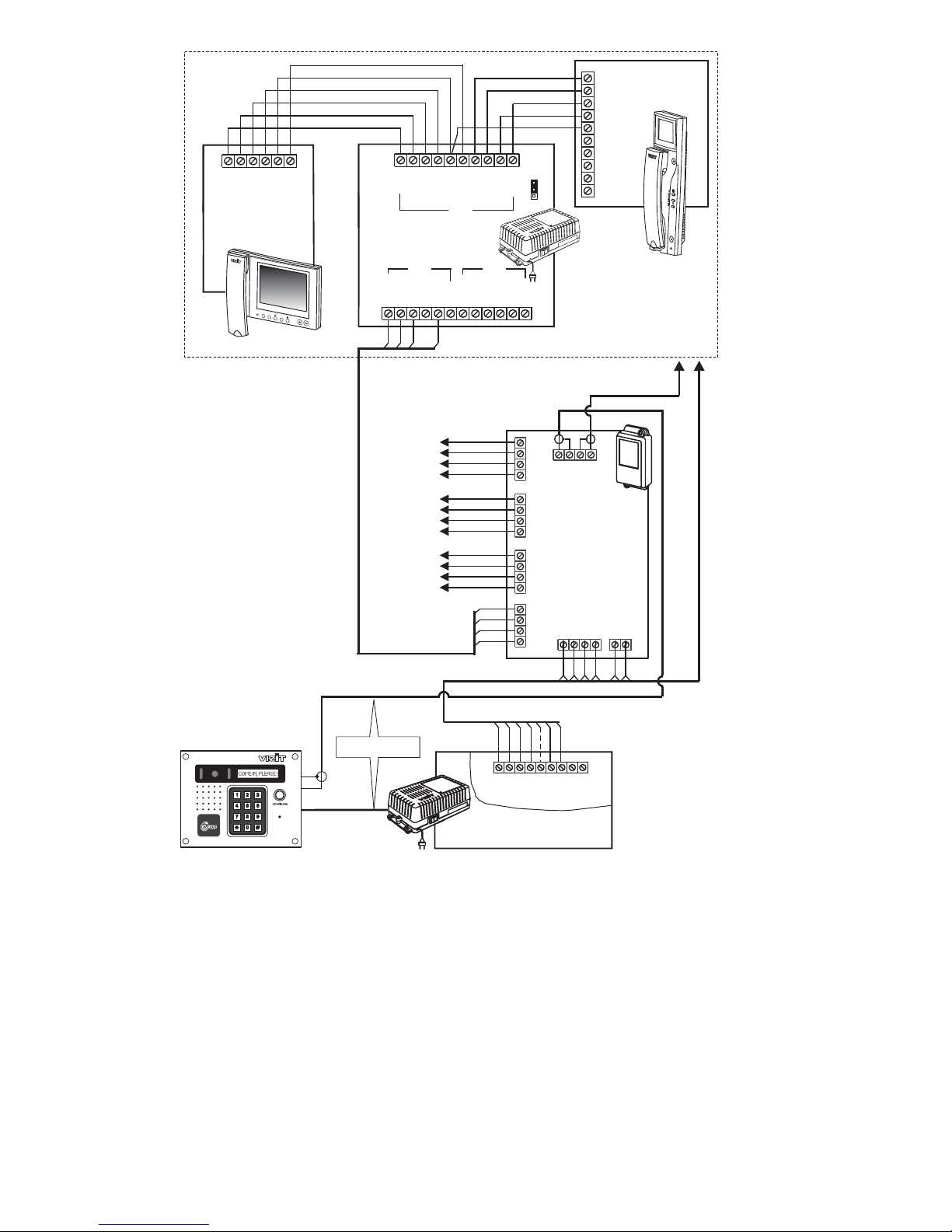
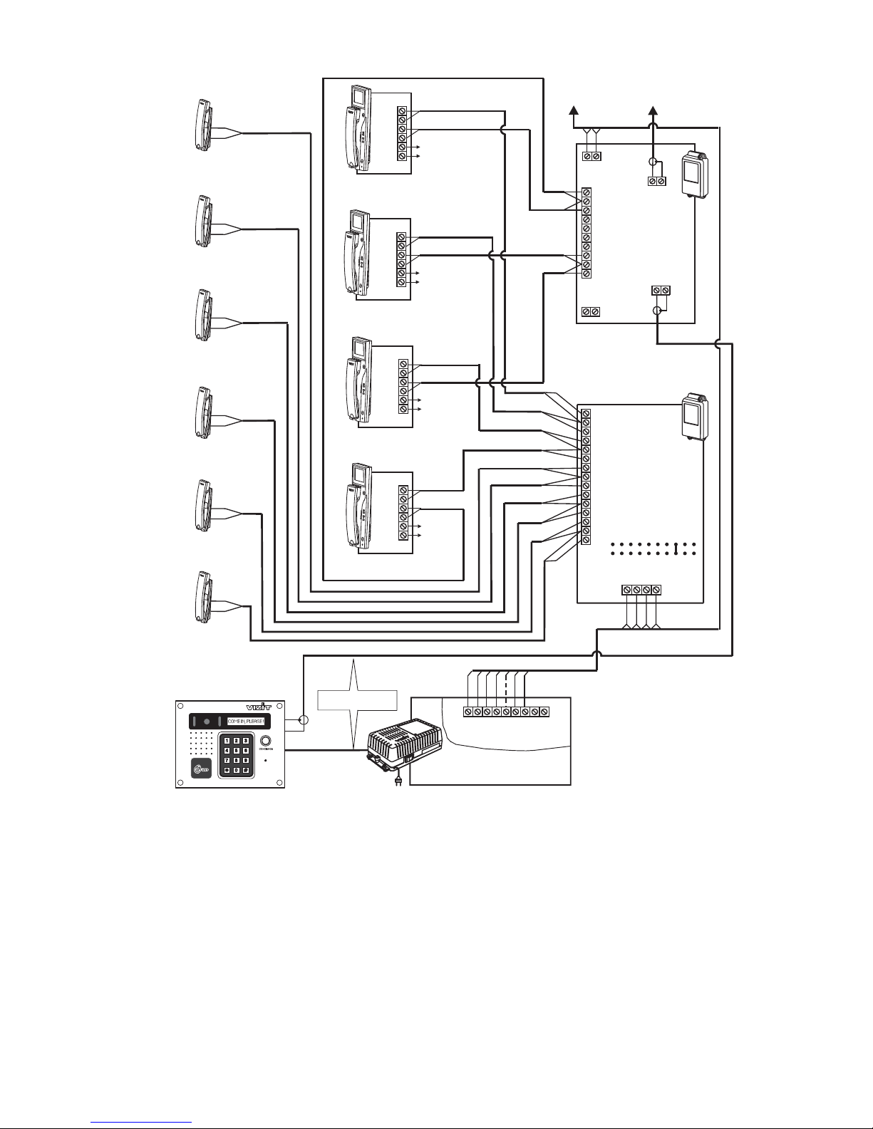
Figure Control Unit with two monitors per apartment
connected through commutator in a multi-apartment video doorphone
5- BUD
BKM
-420М
-440
-18V
+18V
V1
FA
LN
VG
V2
FB
LN
VG
V3
FC
LN
VG
GND
LINE
SEL
Ek
VI
VG
VG
V4
FD
LN
VG
VO
To monitors in apartments
DATA
Monitor
VIZIT-MT460CM
HS+
HS-
LN1-
GND
VI2
+E
LN1+
LN2-
VI1
LN2+
Ec1
Ec2
+E
GND
LN-
GND
LN+
+E
DATA
VO1
HS/MON
EQUIV
AB
C
VO2
GND
LN-
GND
LN+
VI1
+E
DATA
Ec1
Ec2
GND
VI2
Commutator
-440BKM
VIZIT-M430C
Monitor
LN-
GND
LN+
+E
VI
AWAY REC
MENU
To next commutator
BK MV-4
432
1
1
2
3
4
LINE
GND
SEL1
Ek
USE
Evk
GND
GND
SEL0
123467
5
123
46
7
Apartment
The terminal of commutators
connecting apartment handsets /
monitors from apartments with
hundred shall be wired up
to the circuit connected to the
terminal of
If there are total 100 apartment
handsets / monitors or less, the
and terminals of
shall be shorted.
SEL
odd
SEL1 BUD-420M.
SEL0 SEL1
BUD-420M
See Fig.1-3
Control Unit
BUD-420M
Doorstation
-431DXKCB
( -432RCB)
BVD
BVD
-4 V
Commutator
BK M
8
-4
Distribution
Amplifier
RVS
VG
+18
-18
VO
VG
V3
+18
VG
V1
V2
-18
-18
+18
V4
VG
VI
+18
-18
FA
LN
FB
FC
LN
FD
Commutator
-4BK M
LINE
GND
SEL
Ek
76
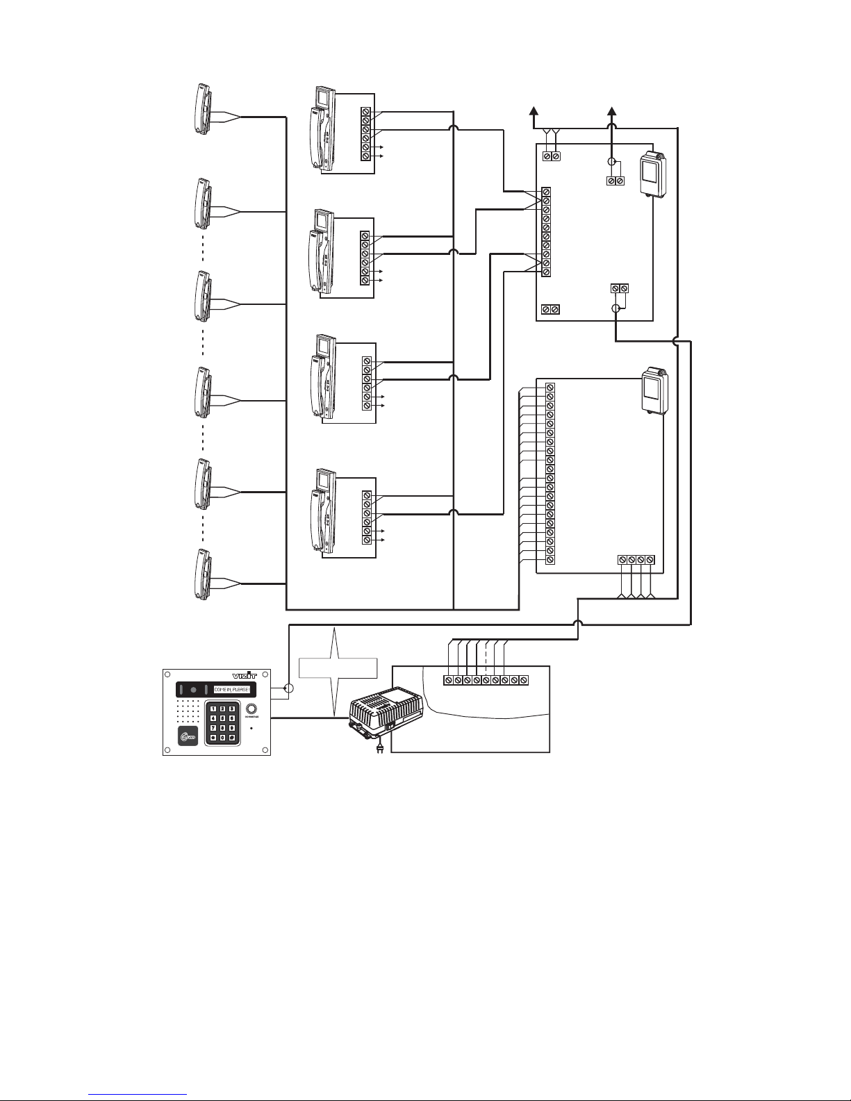
Figure Control Unit with commutators
and distribution amplifier in a multi-apartment video doorphone
6- BUD BK-4M
RVS-4
-420М
1
2
3
4
LN-
GND
LN+
VI1
+E
GND
VIZIT-M430C
Monitor
LINE
GND
SEL1
Ek
USE
Evk
GND
GND
SEL0
123467
5
LN-
GND
LN+
VI1
+E
GND
VIZIT-M430C
Monitor
To next commutators and
distribution amplifier RVS-4
Apartment
Handset
UKP-12(M)
+
-
-12(M)
Apartment
Handset
UKP
To power
supply unit
To power
supply unit
LN
FD
+
-
LN
FC
V4
VG
VG
V1
VG
V1
V4
VG
LN
FC
LN
FD
FA
FB
LN
FA
LN
FB
82
and terminals of the last
-Ohms resistor shall be connected between
in the circuit
VO
VG RVS-4
See Fig.1-3
Control Unit
BUD-420M
Doorstation
-431DXKCB
( -432RCB)
BVD
BVD
The terminal of commutators
connecting apartment handsets /
monitors from apartments with
hundred shall be wired up
to the circuit connected to the
terminal of
If there are total 100 apartment
handsets / monitors or less, the
and terminals of
shall be shorted.
SEL
odd
SEL1 BUD-420M.
SEL0 SEL1
BUD-420M
9
LN
7
LN
6
2
0
LN-
GND
LN+
VI1
+E
GND
LN
LN
LN
LN
7
LN
LN
3
1
5
26
3
8
4
LN
LN
8
VG
V2
LN-
GND
LN+
VI1
+E
GND
4
LN-
GND
LN+
VI1
+E
GND
VIZIT-M430C
1
5
LN
LN
VIZIT-M430C
VIZIT-M430C
VIZIT-M430C
LINE
GND
SEL1
Ek
USE
Evk
GND
GND
SEL0
123467
5
9
0
LN-
GND
LN+
VI1
+E
GND
LN
9
To power
supply unit
To power
supply unit
To power
supply unit
To power
supply
unit
LN
LN
VG
V3
VG
V4
VG
V1
Figure Control Unit with commutator and
distribution amplifier in a multi-apartment video doorphone
7- BUD BK-10
RVS-4
-420М
-
+
-
+
-
+
-
+
-
+
-
+
Apt No.05
Apt No.07
Apt No.06
Apt No.02
Apt No.00
Apt No.01 Apt No.03
Apt No.09
Apt No.04
Apt No.08
82
and terminals of the last
-Ohms resistor shall be connected between
in the circuit
VO
VG RVS-4
See Fig.1-3
Control Unit
BUD-420M
Doorstation
-431DXKCB
( -432RCB)
BVD
BVD
-12(M)UKP
-12(M)UKP
-12(M)UKP
-12(M)UKP
-12(M)UKP
-12(M)UKP 4321
GND
LINE
SEL
Ek
8493762015
VG
V1
+18
V2
-18
+18
-18
V3
+18
V4
VG
-18
Commutator
-10BK
VG
VI
+18
-18
VO
VG
76
To next commutators and
distribution amplifier RVS-4
8
LN
4
9
LN
3
7
LN
LN
LN
6
2
0
1
5
(To apartments
with
hundred
even
)
-4
Distribution
Amplifier
RVS
The terminal of commutators
connecting apartment handsets /
monitors from apartments with
hundred shall be wired up
to the circuit connected to the
terminal of
If there are total 100 apartment
handsets / monitors or less, the
and terminals of
shall be shorted.
SEL
odd
SEL1 BUD-420M.
SEL0 SEL1
BUD-420M
10

LN-
GND
LN+
VI1
+E
GND
VG
V1
LN-
GND
LN+
VI1
+E
GND
LN-
GND
LN+
VI1
+E
GND
LINE
GND
SEL1
Ek
USE
Evk
GND
GND
SEL0
123467
5
LN-
GND
LN+
VI1
+E
GND
To power
supply unit
VG
V2
VG
V3
VG
V4
Figure Control Unit with commutator and
distribution amplifier in a multi-apartment video doorphone
8- BUD BK-30M
RVS-4
-420М
82
and terminals of the last
-Ohms resistor shall be connected between
in the circuit
VO
VG RVS-4
-
+
-
+
-
+
-
+
-
+
DB
E0
DA
E5
DB
E6
DC
E7
DC
E8
DC
E9
DA
E4
DA
E3
DA
E2
DA
E1
Apt. No05
Apt. No29
Apt. No28
Apt. No27
Apt. No16
Apt. No10
Apt. No01
Apt. No02
Apt. No03
Apt. No04
VG
V1
+18
V2
-18
+18
-18
V3
+18
V4
VG
-18
VG
VI
+18
-18
VO
VG
76
4321
E8
E4
E5
E1
E0
E2
E6
E7
E3
E9
GND
LINE
SEL
Ek
DA DA
DB
DC
DB
DC
9
4
8
3
7
6
1
2
0
5
E8
E4
E5
E1
E0
E2
E6
E7
E3
E9
DB
DA
Commutator
-30BK M
V1
VG
V2
V3
VG
V4
DC
See Fig.1-3
Control Unit
BUD-420M
Doorstation
-431DXKCB
( -432RCB)
BVD
BVD
-4
Distribution
Amplifier
RVS
VIZIT-M430C
VIZIT-M430C
VIZIT-M430C
VIZIT-M430C
-12(M)UKP
-12(M)UKP
-12(M)UKP
-12(M)UKP
-12(M)UKP
-12(M)UKP
The terminal of commutators
connecting apartment handsets /
monitors from apartments with
hundred shall be wired up
to the circuit connected to the
terminal of
If there are total 100 apartment
handsets / monitors or less, the
and terminals of
shall be shorted.
SEL
odd
SEL1 BUD-420M.
SEL0 SEL1
BUD-420M
(To apartments
with
hundred
even
)
To next commutators and
distribution amplifier RVS-4
To power
supply unit
To power
supply unit
To power
supply unit
11
LN-
GND
LN+
VI1
+E
GND
VG
V1
+18
V2
-18
+18
-18
V3
+18
V4
VG
-18
VG
V1
LN-
GND
LN+
VI1
+E
GND
LN-
GND
LN+
VI1
+E
GND
LINE
GND
SEL1
Ek
USE
Evk
GND
GND
SEL0
123467
5
LN-
GND
LN+
VI1
+E
GND
VG
VI
+18
-18
VO
VG
76
VG
V2
VG
V3
VG
V4
-
+
-
+
-
+
-
+
4321
E7
D7
E8
D8
E9
D9
E0 D3
E4
D2
E3
D1
E2
D0
E1
Apt. No90
Apt. No89
Apt. No78
Apt. No67
D6
-
+
-
+
D5
E6
D4
E5
Apt. No45
Apt. No56 Apt. No01
Apt. No12
Apt. No23
Apt. No34
V1
VG
V2
V3
VG
V4
E8
E4
E5
E1
E0
E2
E6
E7
E3
E9
GND
LINE
SEL
Ek
E8
E4
E5
E1
E0
E2
E6
E7
E3
E9
D8
D4
D5
D1
D0
D2
D6
D7
D3
D9
D4
D1
D0
D2
D3
Commutator
-100BK M
D6
D7
D9
D8
See Fig.1-3
Control Unit
BUD-420M
Doorstation
-431DXKCB
( -432RCB)
BVD
BVD
-4
Distribution
Amplifier
RVS
VIZIT-M430C
-12(M)UKP
VIZIT-M430C
VIZIT-M430C
VIZIT-M430C
-12(M)UKP
-12(M)UKP
-12(M)UKP
-12(M)UKP
-12(M)UKP
(To apartments
with
hundred
even
)
The terminal of commutators
connecting apartment handsets /
monitors from apartments with
hundred shall be wired up
to the circuit connected to the
terminal of
If there are total 100 apartment
handsets / monitors or less, the
and terminals of
shall be shorted.
SEL
odd
SEL1 BUD-420M.
SEL0 SEL1
BUD-420M
To next commutators and
distribution amplifier RVS-4
82
and terminals of the last
-Ohms resistor shall be connected between
in the circuit
VO
VG RVS-4
To power
supply unit
To power
supply unit
To power
supply unit
To power
supply unit
Figure Control Unit with commutator and
distribution amplifier in a multi-apartment video doorphone
9- BUD BK-100M
RVS-4
-420М
12
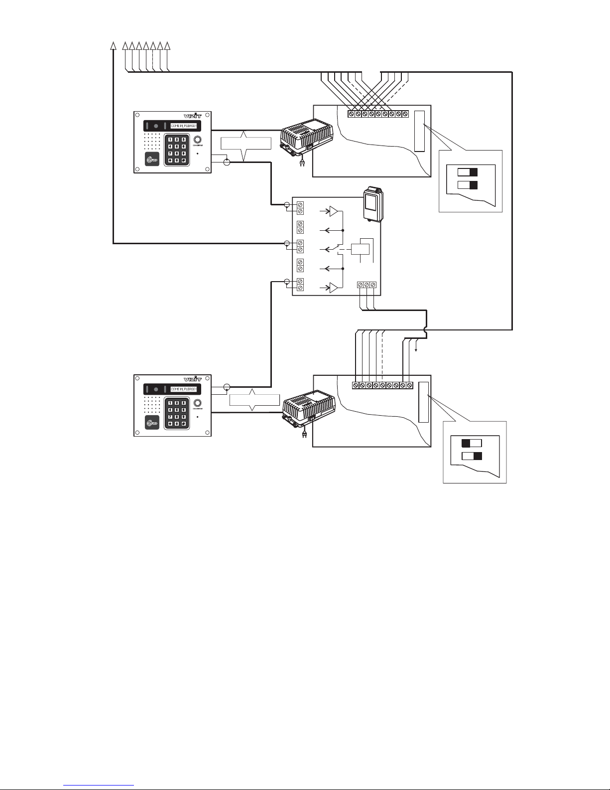
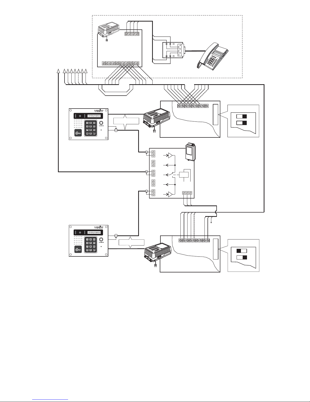
Figure Two Control Units
in a multi-apartment doorphone
10 - BUD-420М
Entrance 1
LINE
GND
SEL1
Ek
USE
Evk
GND
GND
SEL0
1234
2
5
LINE
GND
SEL1
Ek
USE
Evk
GND
GND
SEL0
VG2
VG
VG
VG
VG1
VI2
VO2
VO
VO1
VI1
USE
Evk
GND
Entrance 2
1
3
21
123467
5
To commutators
Commutator
BK-2V
To the terminal
of Control Unit No
“”
2
+E
3
12345
123456 7
SWITCHES
Priority B
1
2
ON
SWITCHES
Priority A
1
2
ON
Control Unit No2
BUD-420M
Doorstation
-431DXKCB
( 432RCB)
BVD
BVD-
Doorstation
-431DXKCB
( -432RCB)
BVD
BVD
Control Unit No1
BUD-420M
See Fig.1-3
See Fig.1-3
13
Entrance 1
LINE
GND
SEL1
Ek
USE
Evk
GND
GND
SEL0
1234
2
5
LINE
GND
SEL1
Ek
USE
Evk
GND
GND
SEL0
VG2
VG
VG
VG
VG1
VI2
VO2
VO
VO1
VI1
USE
Evk
GND
Entrance 2 1
3
21
123467
5
3
Figure Two Control Units and Concierge Console
in a multi-apartment video doorphone
11 - BUD-420М VIZIT- 200PK
Connecting Box
KC-101
Concierge Terminal
VIZIT-TK401D,(DM)
12345
123456 7
INT
+15V
GND
DATA
LN IN
Ek
LN OUT
OP
SEL1
SEL0
GND
LN
+E
Ec
GND
1234
12
3
4
52
3
4
5
1
67
6
7
Concierge
Control Unit
VIZIT-TU412M1
1
4
3
2
Concierge Console
VIZIT- 200PK
SWITCHES
Priority B
1
2
ON
SWITCHES
Priority A
1
2
ON
Doorstation
-431DXKCB
( -432RCB)
BVD
BVD
Doorstation
-431DXKCB
( -432RCB)
BVD
BVD
See Fig.1-3
See Fig.1-3
Control Unit No1
BUD-420M
Commutator
BK-2V
Control Unit No
BUD
2
-420M
To the terminal
of Control Unit No
“”
2
+E
14

PROGRAMMING
system setup service settings
System Setup
12 switches LOCK
Switches
ON
Switches
1 2 PRIORITY
‘A’ ‘D’
3 PASSWORD Service Settings. Service Settings
4 HOTEL No 1534 15 34
Service Settings
5 APARTM. LIST
6 GENERAL CODE
7 INDIVIDUAL CODE
8 KEY RECORD
9 1s LOCK 7s 1 7
10 APARTM. BEEP
11 LANGUAGE -
12 BEEP LEVEL
Service Settings
Note. 8 9 4 (Hotel) System Setup
There are two programming modes: and .
System setup is performed with and the jumper on the Control Unit’s PCB. To access the PCB,
remove the lid from the Control Unit. Set every switch according to the instructions given in the section .
The switch is turned on when set to the position.
and ( ) - set priority for the Control Unit, when there are up to 4 Control Units connected team-working. A
different priority letter assigned to every Control Unit in a team provides a collision-free operation. The table of priority is
drawn on the Control Unit’s PCB, where stands for the highest priority, and for the lowest one.
( ) - enables or disables a password for Apassword is programmed in .
( ) - enables or disables hotel numbering of apartments (e.g.,Apt. - floor , apartment ).
If the switch is ON, a table of correspondence between dialed numbers and their address codes shall be programmed in
.
( ) - enables key memorizing by an apartment list (clusters of up to 6 keys per apartment). If the switch is
off, key memorizing will be performed by a continuous register.
( ) - enables or disables the general access code.
( ) - enables or disables individual access codes.
( ) - enables or disables key memorizing by subscribers.
( ) - sets unlocked state duration (OFF - second, ON - seconds).
( ) - enables or disables a beep in the apartment handset / monitor, when its key / individual access code
is used.
( ) - sets language of displayed MENU and messages (OFF English, ON - Russian).
( ) - sets a volume level for beeps in the doorstation (OFF - low, ON - high).
There are 10 Service Settings programmed through the doorstation keypad. Programming is accompanied with beeps
and messages on the doorstation display. The list of settings and corresponding messages is given in Table 4.
Settings and shall be performed only when Switch is ON (see the section).
Тable 4.
The jumper determines the lock control logic and should comply with the lock type used:
Set the jumper to position in case of an electromagnetic lock. The lock will release, when voltage across its terminals
is off.
Set the jumper to position in case of an electromechanical lock. The lock will release, when voltage across its
terminals is on.
LOCK
ML
EL
Mode
0
1
2
3
4
5
6
7
8
9
Settings Messages
Disabling calls to apartment
New general access code programming
New individual access code programming
Key memorizing
Key erazing
Programming concierge CALL number
Enabling / disabling ТМ-keys DS-1991
Programming new password for service settings
Programming the table of correspondence
between dialed numbers and their addresses
Deleting apartment number from the table of
correspondence
APART. DISABLE
GENERAL CODE
INDIVID. CODE
TM RECORD
TM ERASING
CONCIERGE
ON DS-1991
NEW PASSWORD
TABLE
TABLE EDITING
0
1
2
3
4
5
6
7
8
9
15

Entering Into Service Settings Mode.
3
(PASSWORD)
CHOOSE MODE 0-9 (0-7)
3 PASSWORD
3
, PASSWORD
CHOOSE MODE 0-9 (0-7)
INVALID PASSWORD
, FLAT No
, DONE FLAT No
Note.
!
New General Access Code Programming
, GENERAL CODE
DONE CHOOSE MODE 0-9 0-7
New Individual Access Code Programming
, FLAT No
, INDIVID. CODE
Note.
DONE FLAT No
If there is no programmed password yet (first time programming), or in case of loss of a password, set Switch
to OFF (see ).
Enter into the Service Settings mode.
To re-enable calls to the apartment with disabled calls, just re-program an individual access code for this
apartment.
With disabled calls to the apartment, the individual access code function remains available.
Enter into the Service Settings mode
Enter into the Service Settings mode
System Setup
Disabling Calls To Apartment
Important
·
·
·
·
·
Dial . Two beeps are sounding ( ). You are now in the Service Settings mode. The doorstation is
displaying a message: . If no item is selected within several seconds, the MENU tips are
displayed one by one according to Table 4.
Go through password programming and other settings.
When finished, set Switch ( ) to ON.
If a password is already programmed (Switch is ON):
Dial ( ). The LCD is showing a message: ;
Enter a 4-digit password.
If the password is correct, a beep is sounding ( ). You are now in the Service Settings mode. The doorstation is
displaying a message: . If no item is selected within several seconds, the MENU tips are
displayed one by one according to Table 4.
If the dialed password is invalid, a two-tone beep is sounding, and the LCD is showing: .
Press and redial the password.
1.
2. Press ( ). The LCD is showing: .
3. Dial the apartment number to disable calls. The LCD is showing the dialed number.
4. Press ( ). The LCD is showing: , then .
Repeat actions 3 and 4 to disable calls to more apartments
If the apartment number has 4 digits, do not press .
5. Press to return to Stand-by.
1. .
2. Press ( ). The LCD is showing: .
3. Enter a new 4-digit general access code. The LCD is showing the dialed code,( ).
The LCD is showing: , then ( ).
4. Select the next setting, or press to return to Stand-by.
1. .
2. Press ( ). The LCD is showing: .
3. Dial an apartment number. The LCD is showing the dialed number.
4. Press ( ). The LCD is showing: .
If the apartment number has 4 digits, do not press .
5. Dial digits of a new individual access code for this apartment. The LCD is showing the dialed code, ( ).
5. Dial digits of a new individual access code for this apartment. The LCD is showing the dialed code, ( ).
The LCD is showing: , then .
Repeat actions 3 to 5 to program individual access codes for more apartments.
6. Press to return to Stand-By.
X?
three
three
#999
#999
¬
0
#
#
¬
1
¬
2
#
#
¬
16
Key Memorizing
1200
6
5 APARM. LIST System Setup
Key Memorizing by a continuous register 5
, APPLY TM 0001
DONE APPLY TM 0002.
ALREADY EXISTS.
Key memorizing by the apartment list 5
, FLAT No
, APPLY TM
DONE APPLY TM
MEMORY FULL FLAT No
Note.
FLAT No
Key Erasing
5 APARTM. LIST
, TM OR ITS No
Note 1. NO SUCH TM
Note 2.
The Control Unit BUD-420M allows two key memorizing modes:
- by a continuous register (up to keys), or
- by the apartment list (clusters of up to keys per apartment).
To select a mode, set Switch ( ) to a corresponding position (see the section).
(Switch is OFF)
1. Enter into the Service Settings mode.
2. Press ( ). The LCD is showing: (the displayed numbering corresponds to an ordinal number
of the recorded key).
3. Apply a blank key to the doorstation key reader,
( - pause - ). The LCD is showing: , then:
If the key already exists in the memory, ( - pause - ).
The LCD is showing:
4. Press to return to Stand-By.
(Switch is ON)
1. Enter into the Service Settings mode.
2. Press ( ). The LCD is showing: .
3. Dial the apartment number to which the key will be alloted.
The LCD is showing the dialed number.
4. Press ( ). The LCD is showing: .
5. Apply a blank key to the doorstation key reader,
( - pause - ). The LCD is showing: , then:
At recording the 6th key ( - pause - ),
is showing , then: .
Repeat actions 3 to 5 to record keys for more apartments.
6. Press to return to Stand-By.
If you want to record less than 6 keys per one apartment, then, after you have recorded a desired number of keys,
dial the next apartment number.
The LCD is showing: . Do actions 4 and 5.
Key erasing mode depends on the position of Switch ( ).
1. Enter into the Service Settings mode.
2. Press ( ). The LCD is showing: .
4. Press to return to Stand-By.
If the key does not exist in the memory, the LCD is showing: .
the LCD :
If the key’s ordinal number consists of 4 digits, do not press after dialling.
Switch is OFF.5
3
¬
3
#
¬
3. Dial the key’s ordinal number. The LCD
the dialed number. Press
( ). The LCD : ,
then: .
,
ERASED
TM OR ITS No
is showing
is showing
3.
( - pause - ).
The LCD : ,
then: .
Apply the key you want to delete from
the memory to the doorstation key reader,
ERASED
TM OR ITS No
is showing
4
¬
#
#
17

Switch is ON.
4 digits,
5
1. Enter into the Service Settings mode.
2. Press ( ). The LCD is showing: .
4. Press to return to Stand-By.
If the key does not exist in the memory, the LCD is showing: .
If your doorstation has a CONCIERGE button, it needs to be programmed to its own call number, i.e. any apartment
number which does not exist in the building. The same call number shall be programmed in the Concierge Console.
The default setting is # ).
1. Enter into the Service Settings mode.
2. Press ( ). The LCD is showing: .
3. Dial an apartment number to program for the concierge.
The LCD is showing the dialed number.
4. Press ( ). The LCD is showing: ( ).
5. Select the next setting, or press to return to Stand-By
1. Enter into the Service Settings mode.
2. Press ( ). The LCD is showing: .
3. Dial a new 4-digit password. The LCD is showing the dialed number, ( ).
Then the LCD is showing: , then: ( ).
4. Select the next setting, or press to return to Stand-By.
This setting is available if the hotel numbering of apartments is on: switch ( ) shall be set to ON (see the
section).
The hotel numbering also enables connection of up to 200 apartments (see the
section, Fig ). An apartment number dialed from the doorstation may consist of up to where commutators
selected with the SEL0 or SEL1 terminal can recognize only 2-digit address codes. Thus, according to the Table of
Correspondence programmed in the memory, the Control Unit converts apartment numbers to Sequences. A sequence
number depends on a commutator’s output terminals to which an apartment handset / monitor is connected, and the
position of jumpers.
A fill-out form of table of correspondence for 200 numbers is given in Annex A. An example of filling up the form is given
below in Table 5.
Table 5
, TM OR FLAT No
Note 1. NO SUCH TM
Note 2.
Programming Concierge CALL number
00 0
, FLAT No
, CHOOSE MODE 0-9 0-7
Programming New Password For Service Settings
, NEW PASSWORD
DONE CHOOSE MODE 0-9 0-7
Programming The Table Of Correspondence Between Dialed Numbers And Their Addresses (as recognized in
commutators).
4 HOTEL System
Setup
EXAMPLES OF WIRING DIAGRAMS
1-8
If the key’s ordinal number consists of 4 digits, do not press after dialling.
or #
3. Dial the number of apartment. The LCD
the dialed number. Press
( ). The LCD : ,
then:
All keys of this apartment have
been erased.
,
ERASED
Note.
TM OR FLAT No.
is showing
is showing
3.
( - pause - ).
The LCD : ,
then: .
Apply the key you want to delete from
the memory to the doorstation key
reader,
ERASED
TM OR ITS No
is showing
4
#
¬
#
¬
¬
#
5
7
Sequence No
(recognized in commutators)
Apartment No
(dialed from doorstation)
1
2
...
10
11
...
...
20
101
...
110
101
102
...
110
201
...
...
210
1001
...
1010
18

An a number
Pick up the handset. The LCD : . Check intercom between the handset and doorstation. Adjust
intercom volume for the handset and doorstation, if necessary, with resistors and on the Control Unit’s
PCB.
If acoustic feedback results in whistling, adjust the trimmer resistor on the Control Unit’s PCB. If whistling still
persists, decrease intercom volume with the and resistors.
Press the button on the handset, the lock releases for the period of time set in the System Setup ( or ). While
the button remains pressed, the doorstation is beeping, signalling that the door is unlocked, and the LCD
. After the button is released, the beeps stop and the LCD : . Intercom is
available within seconds.
With pressing and holding the button for more than s, the doorphone goes to Stand-by, the LCD :
Hang up the handset. The doorphone goes to Stand-by.
Press the buttons on the doorstation keypad, and dial the programmed general access code (Switch
shall be ON). The lock releases, beeps are sounding, the LCD : .
partment handset / monitor from the apartment featured in the right column shall be connected to
commutator terminals programmed to a corresponding sequence number featured in the left column.
In Table , a call to Apartment No will be addressed to the apartment handset / monitor with Sequence No , where
a call toApartment No - to the apartment handset / monitor with Sequence No
Fill out the Table of correspondence and program it into the Control Unit’s memory:
1. Enter into the Service Settings mode.
2. Press , ( ). The LCD is showing: .
3. Dial a sequence number (the LCD is showing the dialed number).
4. Press ( ). The LCD is showing: .
5. Dial a corresponding apartment number (the LCD is showing the dialed number).
6. Press ( ). The LCD is showing: .
7. For further programming repeat actions 3 to 6, or press to return to Stand-By.
If a number consists of 4 digits, do not press after dialling.
1. Enter into the Service Settings mode.
2. Press ( ). The LCD is showing: .
3. Dial the apartment number (the LCD is showing the dialed number).
4. Press ( ). The LCD is showing:
5. Repeat actions 3 to 4, or press to return to Stand-By.
If a number consists of 4 digits, do not press after dialling.
After the installation and electric wiring have been complete, disconnect temporarily any of apartment handsets /
monitors from its commutator outputs. Connect a test handset instead of the disconnected one observing polarity. Note that
the test handset shall be hung up.
Turn the Control Unit’s power on. In several seconds the doorstation’s LCD is showing: . Press
the button on the doorstation. The doorstation is beeping at pressing any button.
Dial the apartment number where the test handset is set. The LCD is showing the dialed number. A call sound is ringing
both in the test handset and doorstation, a message appears: .
is showing
is showing:
is showing
is showing
.
,
is showing
If the access code is invalid, or dialed apartment number does not exist, or the key applied to the key reader is not found
in the memory, or Switch is OFF, the doorstation is giving an error beep, the LCD is showing: .
The doorphone goes to Stand-By in seconds. To force the Stand-by mode immediately, press .
Turn the Control Unit’s power off, and disconnect the test handset. Restore the apartment handset / monitor, and turn the
power on.
Press the CONCIERGE button on the doorstation (the concierge number shall be programmed beforehand, see the
section). The LCD is showing: Pick up the Concierge console’s handset and check for
intercom.
Press on the doorstation. The doorphone goes to Stand-by.
5 110 10
1010 110.
SEQUENCE No
, FLAT No
, SEQUENCE No
Note.
, TABLE EDITING
, TABLE EDITING.
Note.
FUNCTIONAL CHECK AND ADJUSTMENT
DIAL THE NUMBER:_
WAIT FOR ANSWER
DIAL
THE NUMBER:_
GENERAL
CODE
6 ERROR. PRESS
5
Service Settings CONCIERGE.
¬
SPEAK
HANDSET DOORST.
BALANCE
HANDSET DOORST.
1s 7s
COME IN, PLEASE SPEAK
80
8
6
COME IN, PLEASE
Deleting Apartment Number From The Table Of Correspondence
9
8
#
#
#
¬
¬
#
#
¬
¬
¬
¬
#
19

One by one, check all connected apartment handsets / monitors for intercom, video (in case of monitors), and remote
door unlocking function.
Program the general access code and individual access codes, if needed.
Check the general access code and individual access codes for door unlocking function.
To make a call to a subscriber, dial the apartment number. The stand-by message “ ” disappears,
and the LCD is showing: .
A call sound is ringing both in the apartment handset / monitor and doorstation. The subscriber picks up the handset to
start intercom, the LCD is showing: . Talk to the subscriber.
To release the doorlock, the subscriber presses the button on the apartment handset / monitor. The door unlocks,
the doorstation is beeping, the LCD is showing: .
Open the door and enter. To return the doorphone to Stand-by, the subscriber hangs up the handset.
. Open the door and enter.
In case of misdial, or Switch is OFF, the doorstation is producing an error beep, the LCD is showing:
. The doorphone goes to Stand-By in seconds. Press and redial the code.
,
. Open the door and enter.
In case of misdial, or Switch is OFF, the doorstation is producing an error beep, the LCD is showing:
. The doorphone goes to Stand-By in seconds. Press and redial the code.
To unlock the entrance door with your key, apply it to the reader - one short beep means that the key is read. If
(search time is 3 s), the door unlocks.
Door unlocking signals and key usage signals are mute during intercom, because the line is busy.
and
shall be ON).
()
OPERATION
DIAL THE NUMBER:_
WAIT FOR ANSWER
SPEAK
COME IN, PLEASE
COME IN,
PLEASE
6 ERROR. PRESS
5
COME
IN, PLEASE
6 ERROR. PRESS
5
Note.
7 INDIVIDUAL CODE 5 APARTM. LIST 8 KEY
RECORD
7 INDIVIDUAL CODE
To unlock the entrance door with the general access code press , then , then dial the code (Switch
shall be ON). If the code is valid, the door unlocks, the doorstation is beeping and the LCD is showing:
To unlock the entrance door with the individual access code, dial the siquence of your apartment number, and your
individual access code . The apartment handset / monitor in your apartment is giving a short beep (if Switch
is ON). If the code is valid, the door unlocks, the doorstation is beeping and the LCD is showing:
The apartment handset / monitor in your apartment is giving a
short beep (if Switch and Switch are ON). If the key code is ,
an error beep is sounding.
To unlock the door from inside of the building, press the button for exit.
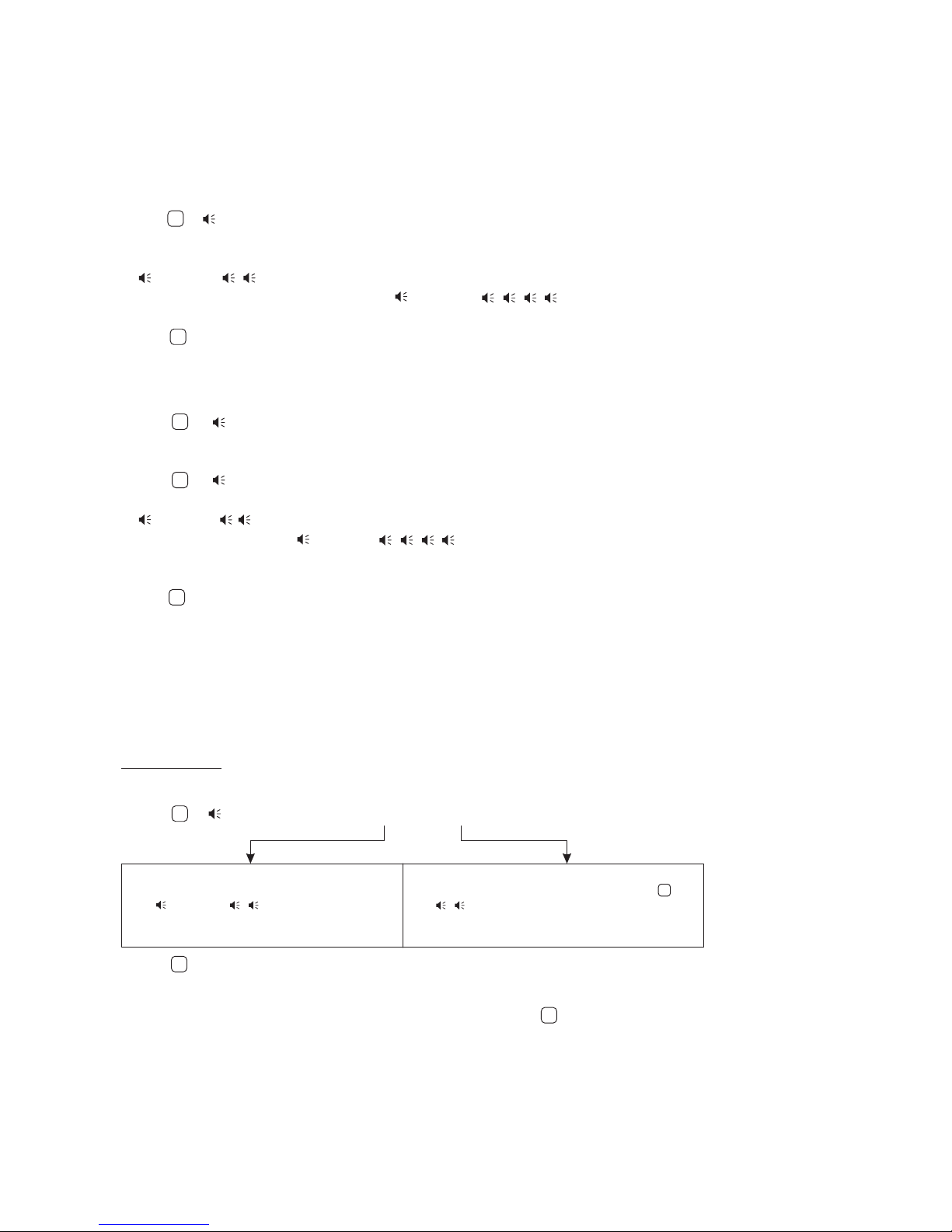
Subscribers may do programming without entering into the service settings mode. They can change an individual
access code (Switch shall be ON), program and delete keys (Switches
The procedure is carried out by two persons. One person shall by near the doorstation (a ‘Visitor’), another one - near an
apartment handset / monitor in the apartment (a ‘Subscriber’).
Subscribers may change individual access codes, if Switch is ON. The procedure is carried out
by two persons, a ‘Visitor’ and ‘Subscriber’.
Dial the apartment number from the doorstation.
When the apartment handset / monitor starts ringing, the ‘Subscriber’ picks up the handset and presses the button 6
times*:
*for apartment handsets - press 6 times without pauses;
for monitors - press and hold each time until a beep.
The doorstation is producing a beep.
Dial 3 digits of a new individual access code, . Inform the ‘Subscriber’ that the new code has been dialed (intercom is
still available).
The ‘Subscriber’ presses the button.
To finish, press on the doorstation, or the ‘Subscriber’ shall hang up the handset.
6 GENERAL
CODE
10 APARTM. BEEP
10 APARTM. BEEP 5 APARTM. LIST
Programming New Individual Access Codes By Subscribers
¬
¬
without pauses
not found in the memory
its code is
found in the memory
·
·
·
·
·
¬
¬
#
#
¬
¬
20
Table of contents
Other ViziT Control Unit manuals


Popular Control Unit manuals by other brands


Controls
Controls MVP-A3238 product manual

Siemens
Siemens RUGGEDCOM RS900 installation guide

Watts
Watts AMES 933GD manual

HMS
HMS Anybus EtherNet/IP How to configure

Singer Valve
Singer Valve 106-RPS-D Installation, operating and maintenance instructions

Honeywell
Honeywell Resideo ADEMCO 4101SN V-Plex Installation and setup guide