Vmac VR70 User manual

VR70 UNDERHOOD
AIR COMPRESSOR
INSTALLATION MANUAL
System V900127
2012 - 2015 GM 2500-3500 Pickup
6.0L Vortec Gas


VMAC – Vehicle Mounted Air Compressors
Toll Free: 1-888-241-2289
Fax: 1-250-740-3201
1
Installation Manual for VMAC
System V900127
2012 - 2015 GM 2500-3500 Pickup, Crew Cab
6.0L Vortec Gas
General Information..................................................................... 4
Before You Start....................................................................... 4
Part 1: Warranty and System ID................................................. 5
Part 2: Preparing for Installation................................................ 7
2.1 Preparing for Installation .................................................... 7
Part 3: Installing the Control Components ............................... 11
3.1 Installing the Components.................................................. 12
3.2 Connecting the In-Cab Wiring............................................ 12
3.3 Connecting the Under-Hood Wiring ................................... 13
Part 4: Installing the Tank and Hoses........................................ 16
4.1 Installing the Tank and Brackets........................................ 16
4.2 Installing the Tank Assembly.............................................. 18
Part 5: Installing the Cooler, Bracket and Compressor........... 21
5.1 Installing the Crank Pulley.................................................. 21
5.2 Modifying the Radiator Hoses............................................ 23
5.3 Installing the Cooler............................................................ 24
5.4 Installing the Hoses............................................................ 25
5.5 Installing the Main Bracket and Compressor ..................... 26
5.6 Connecting the Hoses........................................................ 29
5.7 Completing the Installation................................................. 30
Part 6: Adding Oil to the System............................................... 31
Part 7: Finishing the Installation................................................ 32
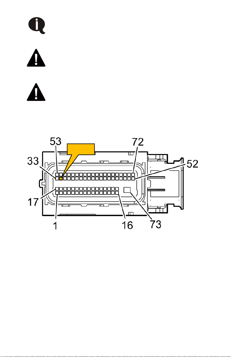
7.1 Connecting to Switched Power 2012 - 2013...................... 32
7.2 Connecting Switched Power 2014 - 2015.......................... 33
7.3 Securing the Wiring............................................................ 39
Part 8 Completing and Testing the Installation........................ 40
Safety Test ............................................................................... 40
Part 9: Finishing the Installation................................................ 41
9.1 Before Starting the Engine Checklist.................................. 41
9.2 After Starting the Engine Checklist .................................... 41
9.3 Final Testing....................................................................... 42
Part 10: Setup, Performance Testing and Adjustments......... 43
Part 11: Optional Accessory Installation ................................. 44
Part 12: Auxiliary Air Receiver ................................................... 45
Part 13: Accessory Products...................................................... 46

VMAC – Truck Mounted Air Compressors
Toll Free: 1-888-241-2289
Fax: 1-250-740-3201
2
Document 1930191
Installation Manual for VMAC System V900127
2012-2015 GM 2500-3500 Vortec 6.0 Gas
Changes and Revisions
Version
Revision Details
Revised by/date
Approved by/date
Implemented
E
ECN 13-106
MC 06 Nov 2013
MP/RD 19 Dec 2013
19 Dec 2013
F
ECN 14-030
AJH 15 May 2014
MP/DB 26 May 2014
26 May 2014
G
ECN 14-084
JR 08 Dec 2014
MH/RD 23 Dec 2014
23 Dec 2014
H
ECN 15-063
RF 17 Jun 2015
SC/RD 18 Jun 2015
18 Jun 2015
J
ECN 15-090
RF 21 Jun 2015
CH/JC 30 July 2015
30 July 2015
Important Information
This symbol is used to call your attention to instructions
concerning your personal safety. Watch for this symbol; it
points out important safety precautions, it means “attention,
become alert! Your personal safety is involved. Read the
message that follows and be alert to the possibility of
personal injury or death. Be alert; your safety is involved.
While it is impossible to warn about every conceivable
hazard, let good common sense be your guide.
This symbol is used to call your attention to additional
instructions or special emphasis on a specific procedure.
The information in this manual is intended for certified VMAC installers
who have been trained in installation procedures and for people with
mechanical trade certification who have the tools and equipment to
properly and safely perform the installation. Do not attempt this
installation if you do not have the appropriate mechanical training,
knowledge and experience.
Follow all safety precautions for under hood mechanical work. Any
grinding, bending or restructuring operations for correct fit in modified
trucks must follow standard shop practices.
All hoses, tubes, and wires that are rerouted or shifted
during installation must be secure so that they do not
contact excessively hot areas or sharp edges. Where
possible, use rubber coated P-clips. Follow the routing
suggestions in this manual and cover all hoses with plastic
loom or equivalent hose protection.

VMAC – Vehicle Mounted Air Compressors
Toll Free: 1-888-241-2289
Fax: 1-250-740-3201
3
These instructions are a general guide for installing this system on
standard production trucks and do not contain information for installation
on non-standard trucks. This system may not fit special order models or
those which have had other changes without additional modifications. If
you have difficulty with the installation, contact VMAC.
The VMAC warranty form is included in the documentation package.
This warranty form must be completed and mailed or faxed to VMAC at
the time of installation for any subsequent warranty claim to be
considered valid. Alternatively, the warranty form can also be found at:
http://vmacair.com/support/warranty
To order parts, contact your VMAC dealer. Your dealer will ask for the
VMAC serial number, part number, description and quantity. To locate
your nearest dealer, call 1-888-241-2289 or visit:
http://vmacair.com/dealer-locator/
Copyright 2015
All trademarks used in this manual are the property of the respective copyright holder.
The contents of this manual may not be reproduced in any form without the express written
permission of VMAC, 1333 Kipp Road, Nanaimo, BC V9X 1R3.
Printed in Canada

VMAC – Truck Mounted Air Compressors
Toll Free: 1-888-241-2289
Fax: 1-250-740-3201
4
General Information
Before You Start
Read this manual before attempting installation so that you can
familiarize yourself with the components and how they fit on the truck.
Identify variations for different model years and different situations that
are listed in the manual. Open the package, unpack the components
and identify them.
All fasteners must be torqued to specifications. Use manufacturers
torque values for OEM fasteners. Apply Loctite 242 or equivalent on
all engine-mounted fasteners. Torque values are with Loctite applied
unless otherwise specified.
STANDARD GRADE 8 NATIONAL COARSE THREAD
Size
1/4
5/16
3/8
7/16
1/2
9/16
5/8
¾
Foot-pounds (ft-lb)
9
18
35
55
80
110
170
280
Newton meter
(N•m)
12 24 47 74 108 149 230 379
STANDARD GRADE 8 NATIONAL FINE THREAD
Size
3/8
7/16
1/2
5/8
¾
Foot-pounds (ft-lb)
40
60
90
180
320
Newton meter (N•m)
54
81
122
244
434
METRIC CLASS 10.9
Size
M8
M10
M12
M14
M16
Foot-pounds (ft-lb)
19
41
69
104
174
Newton meter (N•m)
25
55
93
141
236
Special Tools Required
•OEM flywheel locking tool part number J42386.
•Pneumatic fan wrench removal set (such as Lisle 43300) or a
manual fan pulley holder (such as KD3900)
•Loctite 242
Hose Information
Depending on other installed equipment, it might be necessary to
move the air/oil separation tank from its intended location. The hoses
used in VMAC compressor systems have a specific inner liner that is
compatible with our compressor oil. Use of hoses other than those
supplied or recommended by VMAC may cause compressor damage
and may void your warranty. Please contact VMAC for replacement
hoses and further information.

VMAC – Vehicle Mounted Air Compressors
Toll Free: 1-888-241-2289
Fax: 1-250-740-3201
5
Part 1: Warranty and System ID
□Complete the warranty form.The VMAC warranty form is
located at the back of this manual. This warranty form must be
completed and mailed or faxed to VMAC at the time of installation
for any subsequent warranty claim to be considered valid. This
form can also be found online at:
http://vmacair.com/support/warranty/
System Identification and Operating Instructions
The System Identification Number Plate must be attached to the
vehicle at the time of installation. This plate provides information that
allows VMAC to assist in customer inquiries and ordering of parts.
□Mark and drill two 7/64-inch holes in the top of the cross member
in front of the OEM air filter box. Secure the plate with supplied
self- tapping screws. (Figure 1.1)
Passenger Side
Headlight
System Identification
Number Plate
Passenger Side
Fender
Figure 1.1 – System Identification Plate
□Clean cross member beside the number plate and stick the VMAC
belt routing diagram to the cross member.
□As part of the installation process, ensure that the safety and
operational instruction decal is affixed in an obvious location so
that it can be seen by vehicle operators. A good spot for this is
usually on the inside of the door or on the panel underneath the
steering wheel. (Figure 1.2)

VMAC – Truck Mounted Air Compressors
Toll Free: 1-888-241-2289
Fax: 1-250-740-3201
6
Figure 1.2 – Operating Instructions
□To alert any technicians that may service the vehicle, affix the
servicing caution/contact label in the engine compartment near
the hood latch in a visible location. Thoroughly clean the selected
area before affixing the label (Figure 1.3)
Figure 1.3 – Service label
To order parts, contact your VMAC dealer. Your dealer will ask for the
VMAC serial number, part number, description and quantity. To locate
your nearest dealer, call 1-888-241-2289 or visit www.vmacair.com

VMAC – Vehicle Mounted Air Compressors
Toll Free: 1-888-241-2289
Fax: 1-250-740-3201
7
Part 2: Preparing for Installation
2.1 Preparing for Installation
Preparation for installation is very important. Missing an item can
cause problems in the installation or even damage to components.
Check off each item as it is completed so that you do not miss any
preparation steps.
□Locate the Engine Control Module (ECM) on the inside of the
driver side fender, at the front near the fuse panel. (Figure 2.1)
Figure 2.1 – ECM Location
□Remove electrical tape and peel back plastic loom for connectors
X1 (smallest connector at the top of ECM) and X2 (larger
connector beside X1)
Do not use a test light to probe for power on vehicle
circuits, the increased current draw of the test light may
damage components
ECM
Fuse
Pane

VMAC – Truck Mounted Air Compressors
Toll Free: 1-888-241-2289
Fax: 1-250-740-3201
8
2012 - 2014 trucks have different colour wires than 2015
trucks, pay attention to model year and wire colours.
ECM connector X1 has multiple wires with the same
color. Follow the tests below to determine the correct
wire.
2015: There are two white wires with grey stripe
2014: There are two orange wires with black stripe
Do not use a test light to probe for power on vehicle
circuits, the increased current draw of the test light may
damage components
□Locate the wire going to pin 34 in ECM connector X1 (Figure 2.2)
•2015 white wire with grey stripe
•2012 - 2014 orange wire with black stripe
Figure 2.2 - ECM Connector X1 Front View
□With the engine off, using a voltmeter, probe each wire
•2015 white wire with grey stripe
•2012 - 2014 orange wire with black stripe
and turn the ignition switch to RUN.
□The correct wire will show 0 Volts in PARK or NEUTRAL and 12
Volts in all other gear selector positions.
□Turn the ignition switch off. Mark the correct wire for electrical
connections later in the installation process.
Pin 34

VMAC – Vehicle Mounted Air Compressors
Toll Free: 1-888-241-2289
Fax: 1-250-740-3201
9
□Cut the tape, open and locate the two light green wires in bundle
of the connector ECM-X2 (larger connector beside X1)
(Figure 2.3)
Figure 2.3 - ECM Connector X2 Front View
There are two light green wires in the bundle for ECM-
X2. Follow the tests below to determine the correct
wire.
Do not use a test light to probe for power on vehicle
circuits, the increased current draw of the test light may
damage components
□Using a voltmeter, probe each light green wire and start the
engine.
□The correct wire will show a stable voltage reading of 2.3-2.8 Volts
while the engine is idling.
□Turn the ignition switch off. Mark the correct wire for electrical
connections later in the installation process.
□Disconnect the battery terminals.
□Remove the air filter box, air intake tube and resonator box.
□Remove the engine fan (right hand thread).
Pin 56

VMAC – Truck Mounted Air Compressors
Toll Free: 1-888-241-2289
Fax: 1-250-740-3201
10
□Drain the coolant. Save the coolant, as it will be reused later.
□Remove lower radiator hose.
□Remove the OEM belt.
□Remove the power steering pump from the OEM bracket and
move out of the way, but do not disconnect any of the power
steering lines.
Bolts for power steering pump can be accessed
through pulley. Do not remove pulley from pump.
□Disconnect the wiring and remove the alternator.
□Remove OEM idler pulley from alternator bracket. Save for later
use.
□Remove the OEM aluminum alternator and power steering pump
mounting bracket. Remove the two alternator mount spacers and
save for use in new bracket. Save mounting bolts for use later.
□Clean the inside of the OEM crankshaft pulley and remove the
OEM crankshaft pulley center bolt.
□Remove the air intake box-mounting tray (passenger side). Keep
these bolts, as they will be used later.
□Remove the 2 OEM bolts holding the air intake tray support to the
front radiator support. Keep these bolts, as they will be used later.
□If equipped, remove the fuel line from the plastic clips so that it
can be moved out of the way when mounting the tank.
□If equipped, remove the OEM wire harness securing bracket from
the top of the frame so that it can be moved out of the way when
mounting the tank.

VMAC – Vehicle Mounted Air Compressors
Toll Free: 1-888-241-2289
Fax: 1-250-740-3201
11
Part 3: Installing the Control
Components
Figure 3.1 – Electrical Schematic

VMAC – Truck Mounted Air Compressors
Toll Free: 1-888-241-2289
Fax: 1-250-740-3201
12
3.1 Installing the Components
The control box is not weather proof, ensure it is
sufficiently protected from the elements and physical
damage.
□Install the control box in a convenient location in the cab,
positioned so the wire harness will reach the compressor located
at the front driver side of the engine.
□Mount the throttle control box under the dash using plastic ties.
Select a location that will allow access to the adjusting screws.
3.2 Connecting the In-Cab Wiring
□Connect the interface wire harness connector to the matching
connector from the VMAC control box.
□Disconnect the multi-pin connector from the accelerator pedal and
plug it into to the matching connector at the throttle control box
then plug the connector from the throttle control box into the
accelerator pedal.
□Connect the wires with the ring connector from the throttle control
box and from the interface connector to a good metal ground.
□Connect the red wire from the control box to the red wire from the
throttle control.
□Route the following wires through a suitable firewall plug under
the dash. If necessary, cut a slit in one of the rubber plugs and
pull the wires through into the engine compartment.
•cable with the black 3 pin connector
•cable with the green 4 pin connector
•white wire with the bullet connector
•white wire from the throttle control box
•blue wire from the throttle control box
•red wire from interface cable with inline fuse
□Unplug the connector from the park brake switch and connect the
black wire with the piggyback connector from the interface cable
to the connector on the park brake switch: then connect the OEM
park brake connector to the piggyback connector.

VMAC – Vehicle Mounted Air Compressors
Toll Free: 1-888-241-2289
Fax: 1-250-740-3201
13
3.3 Connecting the Under-Hood Wiring
□Locate the wire marked earlier in the install at ECM X1:
•2015 white wire with grey stripe
•2012 - 2014 orange wire with black stripe
□2015: Solder and seal the long blue wire from the VMAC throttle
to the white wire with the grey stripe (Figure 3.2)
Figure 3.2
□2012 - 2014 Solder and seal the long blue wire from the VMAC
throttle to the orange wire with the black stripe (Figure 3.3)
Figure 3.3
□Slide the heat shrink over the soldered joint and shrink with a heat
gun. Do not overheat and be sure to protect the other nearby wire
bundles with cardboard or sheet metal. (Figure 3.4)
Figure 3.4

VMAC – Truck Mounted Air Compressors
Toll Free: 1-888-241-2289
Fax: 1-250-740-3201
14
□Put the wires back into the OEM loom and wrap with electrical
tape. Use ¼” wire loom to cover wire. Secure with zip-tie
(Figure 3.5)
Figure 3.5
□Locate the light green wire at connector ECM-X2 (wire marked
earlier during the install).
□Solder and seal the white wire from the throttle control to the light
green wire at connector ECM-X2 as shown (Figure 3.6)
Figure 3.6
□Slide the heat shrink over the soldered joint and shrink with a heat
gun. Do not overheat and be sure to protect the other nearby wire
bundles with cardboard or sheet metal. (Figure 3.7)
Figure 3.7

VMAC – Vehicle Mounted Air Compressors
Toll Free: 1-888-241-2289
Fax: 1-250-740-3201
15
□Put the wires back into the OEM loom and wrap with electrical
tape. Use ¼” wire loom to cover wire. Secure with zip-tie
(Figure 3.8)
Figure 3.8
□Remove the cover from the fuse panel and route the red wire with
the fuse tap/holder to the panel. Refer to Part 7.1 for connection
details.

VMAC – Truck Mounted Air Compressors
Toll Free: 1-888-241-2289
Fax: 1-250-740-3201
16
Part 4: Installing the Tank and
Hoses
4.1 Installing the Tank and Brackets
The tank will mount to the passenger side frame rail
between the two body mounts (Figure 4.1)
Figure 4.1
□Place the tank on a work bench with the front (oil filter end) of the
tank to your left. Remove the oil filter from the front of the tank.
□Remove the two ¼” clamp bolts from the C-clamps. Expand the
clamps slightly and slide them over the front of the tank.
□Position the C-clamps about 6 inches from each end of the tank.
□Place the two L-shaped tank strap mounts under the C-clamps
with the right-angle ends facing you and hanging over the edge of
the work bench.
□Align the holes, apply Loctite and thread 5/16 x 1/2 inch bolts with
flat washers into the bottom hole on each bracket, but do not
tighten.

VMAC – Vehicle Mounted Air Compressors
Toll Free: 1-888-241-2289
Fax: 1-250-740-3201
17
□Reinstall the two ¼” clamp bolts in the C-clamps so that the heads
of the bolts face toward you and install the nuts loosely.
□Rotate the tank so that the directional arrow on the end of the tank
is parallel to the work bench and faces toward you (Figure 4.2)
□Check the distance of each C-clamp from the ends of the tank and
tighten the clamp bolts so that the clamps grip the tank securely.
Figure 4.2
□Apply Loctite and insert 5/16 x 1/2 inch bolts through the clips and
the C-clamp and thread them into the mount brackets.
□Center the bolts in the C-clamp slots and tighten them.
□Thread the 1/2 inch and 3/4 inch swivel elbows onto the matching
fittings on the front of the tank, but do not tighten them
□Apply Loctite pipe thread sealant and install a suitable ¾” fitting in
the outlet on the tank. A 90° fitting is required (but not supplied).
Tighten it to about the Four o’clock position for testing, then
reposition as required for final connections (Figure 4.3)

VMAC – Truck Mounted Air Compressors
Toll Free: 1-888-241-2289
Fax: 1-250-740-3201
18
Figure 4.3
4.2 Installing the Tank Assembly
□Insert the threaded end of the cable strap through the single hole
end of the bar straps.
□Place the bar straps in position on the inside of the frame, one in
front of the transmission cross-member and one behind, with the
cable straps over the top of the frame (Figure 4.4)
An additional 17.5” cable strap (2200169) and bar strap
2200111) is provided to accommodate any frame size
variation.
Other manuals for VR70
24
Table of contents
Other Vmac Air Compressor manuals

Vmac
Vmac G300003 User manual

Vmac
Vmac PredatAir Series Specifications

Vmac
Vmac V400010 User manual

Vmac
Vmac UNDERHOOD 40 Series User manual

Vmac
Vmac UNDERHOOD 40 Series User manual

Vmac
Vmac VR70 User manual

Vmac
Vmac UNDERHOOD 40 Series User manual

Vmac
Vmac RAPTAIR60 Installation instructions

Vmac
Vmac UNDERHOOD 40 Series User manual

Vmac
Vmac H400011 User manual

Vmac
Vmac UNDERHOOD 40 Series User manual

Vmac
Vmac V300004 User manual

Vmac
Vmac H400005 Installation instructions

Vmac
Vmac V900104 User manual

Vmac
Vmac UNDERHOOD 40 Series User manual

Vmac
Vmac VR150 User manual

Vmac
Vmac UNDERHOOD 40 Series User manual

Vmac
Vmac V900170 User manual

Vmac
Vmac PREDATAIR User manual

Vmac
Vmac VR70 Manual