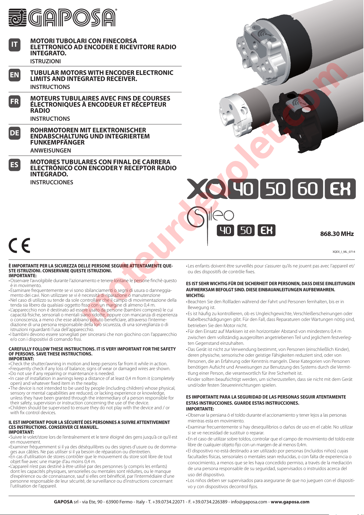
GAPOSA XQ40EX User manual

È IMPORTANTE PER LA SICUREZZA DELLE PERSONE SEGUIRE ATTENTAMENTE QUE-
STE ISTRUZIONI. CONSERVARE QUESTE ISTRUZIONI.
IMPORTANTE:
•Osservarel’avvolgibiledurantel’azionamentoetenerelontanelepersonenchèquesto
èinmovimento.
•Esaminarefrequentementesevisonosbilanciamentiosegnidiusuraodanneggia-
mentodeicavi.Nonutilizzareseviènecessitàdiriparazioneomanutenzione
•Nelcasodiutilizzosutendedasolecontrollarecheilcampodimovimentazionedella
tendasialiberodaqualsiasioggettossoconunmarginedialmeno0,4m.
•L’apparecchiononèdestinatoadessereusatodapersone(bambinicompresi)lecui
capacitàsiche,sensorialiomentalisianoridotte,oppureconmancanzadiesperienza
oconoscenza,amenocheesseabbianopotutobeneciare,attraversol’interme-
diazionediunapersonaresponsabiledellalorosicurezza,diunasorveglianzaodi
istruzioniriguardantil’usadell’apparecchio.
•Ibambinidevonoesseresorvegliatipersincerarsichenongiochinoconl’apparecchio
e/oconidispositividicomandossi.
CAREFULLY FOLLOW THESE INSTRUCTIONS. IT IS VERY IMPORTANT FOR THE SAFETY
OF PERSONS. SAVE THESE INSTRUCTIONS.
IMPORTANT:
•Checktheshutter/awninginmotionandkeeppersonsfarfromitwhileinaction.
•Frequentlycheckifanylossofbalance,signsofwearordamagedwiresareshown.
•Donotuseifanyrepairingormaintenanceisneeded.
•Incaseofinstallationinawningskeepadistanceofatleast0,4mfromit(completely
open)andwhateverxediteminthenearby.
•Thedeviceisnotintendedtobeusedbypeople(includingchildren)whosephysical,
sensoryormentalcapabilitiesarereduced,orlackingexperienceorknowledge,
unlesstheyhavebeengrantedthroughtheintermediaryofapersonresponsiblefor
theirsafety,supervisionorinstructionconcerningtheuseofthedevice.
•Childrenshouldbesupervisedtoensuretheydonotplaywiththedeviceand/or
withxcontroldevices.
IL EST IMPORTANT POUR LA SÉCURITÉ DES PERSONNES A SUIVRE ATTENTIVEMENT
CES INSTRUCTIONS. CONSERVER CE MANUEL.
IMPORTANT:
•Suivrelevolet/storelorsdel’entraînementetleteniréloignédesgensjusqu’àcequ’ilest
enmouvement.
•Examinerfréquemmentsiilyadesdéséquilibresoudessignesd’usureoudedomma-
gesauxcâbles.Nepasutilisersiilyabesoinderéparationoud’entretien.
•Encasd’utilisationdestorescontrôlerquelemouvementdustoresoitlibredetout
objetxeavecunemarged’aumoins0,4m.
•L’appareiln’estpasdestinéàêtreutilisépardespersonnes(ycomprislesenfants)
dontlescapacitésphysiques,sensoriellesoumentalessontréduites,oulemanque
d’expérienceoudeconnaissance,saufsiellesontbénécié,parl’intermédiaired’une
personneresponsabledeleursécurité,desurveillanceoud’instructionsconcernant
l’utilisationdel’appareil.
•Lesenfantsdoiventêtresurveilléspours’assurerqu’ilsnejouentpasavecl’appareilet/
oudesdispositifsdecontrôlexes.
ES IST SEHR WICHTIG FÜR DIE SICHERHEIT DER PERSONEN, DASS DIESE EINLEITUNGEN
AUFMERKSAM BEFOLGT SIND. DIESE EINBAUANLEITUNGEN AUFBEWAHREN.
WICHTIG:
•BeachtenSiedenRollladenwährendderFahrtundPersonenfernhalten,biserin
Bewegungist.
•Esisthäugzukontrollieren,obesUngleichgewichte,Verschleißerscheinungenoder
Kabelbeschädigungengibt.FürdenFall,dassReparaturenoderWartungennötigsind,
betriebenSiedenMotornicht.
•FürdenEinsatzaufMarkisenisteinhorizontalerAbstandvonmindestens0,4m
zwischendemvollständigausgerolltenangetriebenenTeilundjeglichemfestverleg-
tenGegenstandeinzuhalten.
•DasGerätistnichtzurVerwendungbestimmt,vonPersonen(einschließlichKinder),
derenphysische,sensorischeodergeistigeFähigkeitenreduziertsind,odervon
Personen,dieanErfahrungoderKenntnismangeln.DieseKategorienvonPersonen
benötigenAufsichtundAnweisungenzurBenutzungdesSystemsdurchdieVermit-
tlungeinerPerson,dieverantwortlichfürihreSicherheitist.
•Kindersolltenbeaufsichtigtwerden,umsicherzustellen,dasssienichtmitdemGerät
und/oderfestenSteuereinrichtungenspielen.
ES IMPORTANTE PARA LA SEGURIDAD DE LAS PERSONAS SEGUIR ATENTAMENTE
ESTAS INSTRUCCIONES. GUARDE ESTAS INSTRUCCIONES.
IMPORTANTE:
•Observarlapersianaóeltoldoduranteelaccionamientoytenerlejosalaspersonas
mientrasestaenmovimiento.
•Examinarfrecuentementesihaydesequilibriosodañosdeusoenelcable.Noutilizar
sisevenecesidaddesustituiroreparar.
•Enelcasodeutilizarsobretoldos,controlarqueelcampodemovimientodeltoldoeste
libredecualquierobjetojoconunmargendealmenos0,4m.
•Eldispositivonoestádestinadoaserutilizadoporpersonas(incluidosniños)cuyas
facultadesfísicas,sensorialesomentalesseanreducidas,oconfaltadeexperienciao
conocimiento,amenosqueseleshayaconcedidopermiso,atravésdelamediación
deunapersonaresponsabledesuseguridad,supervisadosoinstruidosacercadel
usodeldispositivo.
•Losniñosdebensersupervisadosparaasegurarsedequenojueguenconeldispositi-
voycondispositivosdecontroljos.
XQEX_I_ML_0714
GAPOSA srl - via Ete, 90 - 63900 Fermo - Italy - T. +39.0734.22071 - F. +39.0734.226389 - inf[email protected]om - www.gaposa.com
868.30 MHz
MOTORI TUBOLARI CON FINECORSA
ELETTRONICO AD ENCODER E RICEVITORE RADIO
INTEGRATO.
ISTRUZIONI
TUBULAR MOTORS WITH ENCODER ELECTRONIC
LIMITS AND INTEGRATED RECEIVER.
INSTRUCTIONS
MOTEURS TUBULAIRES AVEC FINS DE COURSES
ÉLECTRONIQUES À ENCODEUR ET RÉCEPTEUR
RADIO
INSTRUCTIONS
ROHRMOTOREN MIT ELEKTRONISCHER
ENDABSCHALTUNG UND INTEGRIERTEM
FUNKEMPFÄNGER
ANWEISUNGEN
MOTORES TUBULARES CON FINAL DE CARRERA
ELECTRÓNICO CON ENCODER Y RECEPTOR RADIO
INTEGRADO.
INSTRUCCIONES
IT
EN
FR
ES
DE
moteurdevolet.com

3x0.75 mm2 /3x18 AWG
230 V~ / 50 Hz 120 V~ / 60 Hz
Fase-Phase-Leitung Marrone-Brown-Marron
Braun-Marrón Rosso-Red-Rouge-Rot-Rojo
Neutro-Neutral-Neutre Blu-Blue-Bleu-Blau-Azul Bianco-White-Blanc-Weiß-Blanco
Terra-Ground-Terre-Erde-Tierra Giallo/Verde-Yellow/Green-Jaune/Vert
Gelb/Grün-Amarillo/Verde Verde-Green-Vert-Grün
Fig. 2
Controllare che la tensione di rete disponibile sull’impianto sia quella indicata sull’etichetta.
Check that the power supply corresponds to the label data.
Verifiez que la tension d’alimentation disponible est celle indiquée sur l’etiquette.
Prüfen Sie, ob die auf dem Klebezettel angegebene Spannung der Netzversorgung entspricht.
Controlar che la tensión de alimentación sea la indicada en la etiqueta.
230 V~ / 50 Hz
120 V~ / 60 Hz
Alimentazione / Power supply
Alimentation / Versorgung
Alimentacción
Fig. 1
F
90°
min 1,8
m
C
Fig. 1.2 B
Fig. 1.1 A
Fig. 1.3 E
F
D
moteurdevolet.com

SALITA (1)
aprelatenda/tapparella;
STOP (2)
fermailmotoriduttore.
DISCESA (3)
chiudelatenda/tapparella.
Prog-TX (4)
programmailtrasmettitore;
Prog-FC (5)
programmainecorsa;
La programmazione e la rego-
lazionedeinecorsadelmoto-
riduttoreavvengono attraverso
i tasti. A seconda del tipo di
trasmettitore usato questi tasti
possono essere posizionati di-
versamente come ragurato
nellegurequiriportate.
IT
Limit-switchprogrammingand
adjustment are made through
the following buttons. Accor-
dingtothetypeoftransmitters
usedthesebuttonscanbedif-
ferentlyplacedasshowninthe
pictures.
UP (1)
themotorliftstherolling
shutter/awningup;
STOP (2)
therollingshutter/awning
stops;
DOWN (3)
therollingshutter/awninggoes
down.
Prog-TX (4)
recordthetransmitter;
Prog-FC (5)
setthelimitswitch;
EN
La programmation et le régla-
ge des ns de courses se font
à travers les boutons suivants.
Selonletyped’émetteurutilisé
cestouchespeuventêtreposi-
tionnés diéremment, comme
indiquédanslesimages.
MONTEE (1)
onactionnelaMontée;
STOP (2)
onactionnelaStop.
DESCENTE (3)
onactionnelaDescente.
Prog-TX (4)
onmémorisel’émetteur;
Prog-FC (5)
onprogrammelesFDC;
FR
Laprogramaciónyelajustede
losnalesdecarrerasecumple
atravésdelasteclas.
Seguneltipodetransmisoruti-
lizado estas teclas pueden ser
posicionadosdeformadiferen-
tecomosemuestraenlasgu-
rasdeestedocumento.
SUBIDA (1)
elmotoreductorlevantala
persiana/toldo.
STOP (2)
elmotoreductorsepara.
BAJADA (3)
elmotoreductorbajarála
persiana/toldo.
Prog-TX (4)
programaeltransmisor;
Prog-FC (5)
programalosnalesdecarrera.
ES
Endabschaltungen Program-
mierung und Einstellung sind
durch den folgenden Tasten
durchgeführt. Je nach Art des
verwendeten Senders können
diese Tasten unterschiedlich
positioniertwerden,wieinden
Figurengezeigt.
AUF (1)
DerMotorfährtauf
STOP (2)
DerMotorstoppt
AB (3)
DerMotorfährtrunter
Prog-TX (4)
EinlernendesSenders
Prog-FC (5)
Einstellungderelektronischen
DE
QCXTAB / QCXTAB4
QCTX1 / QCTX2 / QCTX5
1
3
5
2
4
5
4
1
3
2
Fig. 4
Fig. 3
moteurdevolet.com

►DESCRIZIONE
Motoriduttore tubolare con finecorsa elettronico e ricevitore radio
868,30 MHz. Nella memoria del ricevitore possono essere memorizzati
fino a 28 codici di altrettanti trasmettitori. La regolazione dei finecorsa
e della posizione intermedia così come il normale azionamento avviene
completamente via radio tramite i trasmettitori GAPOSA. La portata
utile dei trasmettitori è di 20mt in spazio chiuso e di 200mt in spazio
libero.
►INSTALLAZIONE (Fig. 1)
ATTENZIONE: il motoriduttore deve essere sempre installato nel tubo prima
di azionarlo perché il controllo elettronico della variazione di velocità non
permette al motore di girare se il trascinatore finecorsa non ruota insieme.
ATTENZIONE: In una installazione con più motori la distanza minima tra loro
(misurata fra le antenne) deve essere di almeno 1/2 metro.
Il motoriduttore deve essere completato con una coppia di adattatori
(corrispondenti con il rullo avvolgitore) e con una piastra di sostegno. Per gli
accessori vogliate riferirvi al ns. catalogo di vendita.
ATTENZIONE: l’installazione non corretta può causare gravi ferite. Seguire
tutte le istruzioni di installazione. Prima dell’installazione rimuovere tutti
i cavi superflui e disattivare qualunque apparecchiatura presente non
necessaria per il funzionamento.
- Applicare gli adattatori sul motoriduttore distinguendo la corona finecorsa
(Fig.1.1A) dalla puleggia motrice (Fig. 1.2 B).
- Lapiastradisostegnodelmotoriduttore(C)vafissataall’internodelcassonettoo
sull’armaturadellatendainmodocheilrulloavvolgitore(F)siaperfettamentein
orizzontale ed ad un’altezza non inferiore a 1,8m.
- Infilare il motoriduttore (E) nel rullo avvolgitore (F) fino a che l’estremità dello
stesso sia sulla battuta dell’anello di comando del finecorsa (Fig. 1.3).
- [Per XQ50] Appoggiare il perno quadro (D) del motoriduttore nella piastra di
sostegno (C) e la calotta all’estremità opposta del rullo sull’apposito supporto.
ATTENZIONE: Non battere mai sul perno quadro del motore per introdurlo nel
tubo.
- Per la serie XQ50 con coppia nominale fino a 15 Nm il diametro minimo del
rulloavvolgitoreè di50x1,5mm;percoppie superiori ildiametrominimo èdi
60x1,5mm.
- Per la serie XQ60 il diametro minimo del rullo avvolgitore è di 63x1,5mm.
- Levitidifissaggiodellasteccasul rullo,nondevonotoccarela partetubolare
del motoriduttore. Vogliate utilizzare delle viti adatte o le clips di fissaggio.
- Parti in movimento del motore montate al di sotto di una altezza di 2,5m dal
suolo devono essere protette.
- L’installazioneinadeguatadelmotoriduttorepuòprovocaredanniapersoneo
cose.
►COLLEGAMENTO ELETTRICO (Fig. 2)
Controllare che la tensione di rete disponibile sull’impianto sia quella
indicata sull’etichetta. Il collegamento alla rete del motoriduttore deve essere
eseguito, secondo lo schema a pagina seguente, da tecnici qualificati in grado
di operare nel rispetto delle norme. Il motoriduttore può essere collegato in
parallelo con altri motori elettronici radio.
ATTENZIONE:
- Nella rete di alimentazione deve essere presente un dispositivo di
sezionamento con distanza di apertura tra i contatti di almeno 3mm.
Per i modelli serie XQ50 con finecorsa senza manovra di soccorso, se il cavo
di alimentazione è danneggiato, esso deve essere sostituito da un cavo o un
assieme speciali disponibili presso il costruttore o il suo servizio assistenza
tecnica (Fig. 3).
►PROCEDIMENTO DI MEMORIZZAZIONE IN INSTALLAZIONI CON DIVERSI
MOTORIDUTTORI RADIO [solo per XQ50]
Se l’installazione prevede la presenza di più XQ EX, nella fase della prima
programmazione occorre alimentare un solo motoriduttore per evitare qualsiasi
interferenza con gli altri (perdita della programmazione o inversione del senso
di rotazione). Per evitare di disconnettere i motori non ancora memorizzati si
può procedere alla memorizzazione attraverso il pulsante bianco sulla testa
motore. Questo pulsante ha la stessa funzione di programmazione del PROG-
TX pertanto la procedura è la stessa indicata in precedenza. L’effetto però è
differente perché in tal caso si attiva il procedimento di memorizzazione del solo
motore interessato.
►MEMORIZZAZIONE/AGGIUNTA DI TRASMETTITORI
ATTENZIONE: Se l’installazione prevede la presenza di più motori con
ricevente, nella fase della prima programmazione occorre alimentare un solo
motore alla volta per evitare qualsiasi interferenza con gli altri.
1. Alimentate il motore da programmare.
2. Tenere premuto il tasto PROG-TX finchè il motore inizia a muoversi.
3. Controllate il senso di rotazione del motore, rilasciate PROG-TX (il motore si
ferma).
4. Premere entro 5 secondi il tasto corrispondente (SALITA se il motore ruota
in salita o DISCESA se viceversa).
In questo modo il trasmettitore è stato memorizzato e sincronizzato il senso di
rotazione del motore.
►CONTROLLO / CAMBIO DEL SENSO DI ROTAZIONE
1.Premere SALITA o DISCESA, il motore dove SALIRE o SCENDERE. In caso
contrario, per cambiare senso di rotazione.
2.Premere e tenere premuto PROG-TX finché il motore non inizia a muoversi.
3.Premere STOP: il motore fa un piccolo movimento nei due
sensi. In questo modo il senso di rotazione è stato invertito.
IMPORTANTE: il cambio di direzione va effettuato prima di regolare i finecorsa
altrimenti questi vengono cancellati.
►CANCELLAZIONE DI UN TRASMETTITORE O UN CANALE
Schiacciate simultaneamente PROG-TX e STOP del trasmettitore da cancellare
finchè il motore fa un piccolo movimento nei due sensi. Solo il trasmettitore
usato nella procedura sarà cancellato dalla memoria.
►RESET DELLA MEMORIA DEL TRASMETTITORE (CANCELLANDO TUTTI I
TRASMETTITORI/CANALI E SENSORI)
Opzione 1
Utilizzando un trasmettitore già programmato premere e tenere premuto
PROG-TX e STOP finchè il motore prima faccia un breve movimento e poco
dopo un secondo più lungo.
La memoria è così cancellata
Opzione 2
1. Senza un trasmettitore già programmato togliere l’alimentazione al motore
e poi ricollegarla.
2. Entro 8 secondi, utilizzando un trasmettitore GAPOSA a 868.30MHz, premere
e tenere premuto PROG-TX e STOP finchè il motore prima faccia un lungo
movimento.
La memoria è cancellata.
►SETTAGGIO FINECORSA
(Solo per motori con finecorsa elettronico)
ATTENZIONE: IL PRIMO FINECORSA DA REGOLARE È SEMPRE QUELLO DI
SALITA
1. Tenere premuto PROG-FC finchè il motore fa un piccolo movimento nei due
sensi.
Nota: durante la fase di programmazione le operazioni sono effettuate
a“uomo-presente”.
2. Premere e tenere premuto SALITA e far raggiungere la posizine di finecorsa
SALITA desiderata.
3. Premere STOP per confermare la posizione di finecorsa SALITA desiderata.
Il motore effettua un piccolo movimento.
4. Premere e tenere premuto DISCESA fino a raggiungere la posizione di
finecorsa DISCESA desiderata.
5. Premere STOP per confermare la posizione di finecorsa DISCESA desiderata.
Il motore effettua un piccolo movimento.
Nota: Un settaggio più accurato dei finecorsa in salita e in discesa può
essere effettuato premendo una seconda volta PROG-FC: il motore si
muoverà lentamente a scatti fino a raggiungere la posizione di finecorsa
desiderata. Premere STOP per confermare la posizione.
►SETTAGGIO AUTOMATICO DEI FINECORSA
For limits set with torque sensor ( mechanical stop of shutters or cassette
awnings/shades), premere e tenere premuto SALITA finché the bottom bar
hits the cassette or shutter box.
Un breve movimento indica che la posizione SALITA è stata memorizzata. La
stessa procedura va seguita per il finecorsa DISCESA ma solo per le serrande.
►SETTAGGIO POSIZIONE INTERMEDIA
Portare l’avvolgibile/tenda nella posizione intermedia
desiderata quindi premere contemporaneamente SALITA e DISCESA finchè
il motore fa un piccolo movimento nei due sensi. La posizione intermedia è
memorizzata
►RICHIAMARE LA POSIZIONE INTERMEDIA
Premere e tenere premuto STOP per almeno 3 secondi: l’avvolgibile/tenda si
muoverà fino a raggiungere la posizione intermedia
►CANCELLARE LA POSIZIONE INTERMEDIA
Premere contemporaneamente SALITA e DISCESA finchè il motore fa un
piccolo movimento nei due sensi di rotazione.
IT
moteurdevolet.com

►DESCRIPTION
Tubular motor designed for rolling shutters, blinds and awnings.
It features an integrated receiver (868,30 MHz) with remote limit
setting and remote user programmable intermediate stop. It works
with GAPOSA transmitters.
Motor’s memory capacity: maximum of 28 transmitters.
Transmitters’ range: 20 m indoor and 200 m outdoor.
►INSTALLATION (Fig. 1)
WARNING: Tubular motor must be always installed in the tube first before
putting it into action since the electronic control of the speed variation do not
enable the motor to turn if the limit switch drive do not turn with it.
WARNING: The mounting distance between two motor heads should not be
less than 1/2m;
To complete installation, the motor must be provided with a couple of adaptors
(corresponding with the tube) and a fixing bracket. For a list of the available
accessories, refer to the catalogue.
WARNING: incorrect installation can cause serious injuries. Follow the
installation instructions. Before you remove all unnecessary cables and turn
off any equipment not required for this operation.
- Fix the adaptors to the motor distinguishing the limits ring (Fig. 1.1 A) from the
drive pulley ( (Fig. 1.2 B).
- Turn and lock the clip after inserting it in the drive-shaft groove.
- Thefixingbracket(C)mustbefixedinsidetheboxorontheawningframesothat
the roller tube (F) is perfectly horizontal and at a height not less than 1,8m.
- Insert the motor (E) into the tube (F) until its end stops against the limits ring.
- [For XQ50] Place the motor square pin (D) on the bracket (C) and the cap at the
opposite end of the tube on the fixing plate.
WARNING: Never hit on the head of the motor (D) when you insert it into the
tube.
For the 50 range, with torque up to 15Nm, the minimum tube diameter is
50x1,5mm; for motors with higher torques, the minimum tube diameter is
60x1,5mm. For the 60 range, the minimum tube diameter is 63x1,5mm.
WARNING:
- The screws used to fix the last slat on the tube may be too long and reach the
tubular part of the motor. Use appropriate screws or fixing clips.
- Motor moving parts installed under 2,5m from the ground must be
protected.
- A wrong motor installation can damage persons or objects.
►WIRING (Fig. 2)
Checkthatthemainsvoltageavailableonthesystemisasshownonthelabel.
The motor mains connection should be executed according to the diagram on
the next page, by qualified technicians able to operate in compliance with the
rules.
ATTENTION:
- The power supply must contemplate a switching device with an opening
distance between contacts of at least 3mm.
For models range XQ50 with limit switches without manual override, in case the
supply cable is damaged, it must be replaced by another cable or a special set
available by the manufacturer or his technical assistance (Fig. 3).
►PROGRAMMING THE FIRST TRANSMITTER (Fig. 4)
The first transmitter to be programmed is called MASTER.
It is the only transmitter by means of which You can enter the programming
mode.
NOTE: If the MASTER must be replaced, you have to RESET the memory of the
receiver and then program a new transmitter as MASTER.
1. For initial programming provide power only to the motor being programmed;
2.Press and hold Prog-TX button of transmitter till the motor starts moving.
3.CheckthemotordirectionthenreleasetheProg-TXbuttonand within5seconds
press the UP button of the transmitter;
4.If, on the contrary, pressing the Prog-TX button the motor turns DOWNWARDS,
releasetheProg-TXbuttonandpresstheDOWNbuttonofthetransmitterwithin5
seconds. The MASTER transmitter is now programmed and the direction of the
motor synchronized with the buttons of the transmitter itself.
Now verify the motor directions (if UP on the transmitter corresponds to UP on
the end-product).
ATTENTION! As long as You press the Prog-TX, the motor turns in a direction.
Releasing Prog-TX the motor stops, then pressing it again, the motor turns
again in the opposite direction (sequential fashion).
►PROGRAMMING PROCEDURE IN INSTALLATION MADE UP OF SEVERAL XQ
EX [only for XQ50]
If the installation is made up of several XQ-EX, only one RI motor must be
powered during programming. All the other motors must be disconnected
in order to avoid interferences, unless You program the transmitter through
the white button on the head. The white-button on the motor-head avoids
power disconnection of every motor. This button has the same programming
function as the Prog-TX on the transmitter and for this reason, the programming
procedure is the same as described above. The result, on the contrary, is different
since through the white-button you only program the motor it belongs to.
►PROGRAMMING / ADDING TRANSMITTER
CAUTION: If more motors with receiver have to be installed,
it is important to power up only one motor at time during the first
programming session, in order to avoid any interferences with the others.
1. Power up the motor to be programmed.
2. Hold PROG-TX pressed until the motor starts moving.
3. Check the rotation of the motor, then release PROG-TX (the motor stops).
4.Within 5 seconds press the corresponding button (i.e. UP if the motor
rotates
upwards or DOWN if vice versa).
In this way the transmitter has been programmed and the rotation of the motor
has been syncronized.
►CHECKING / CHANGING DIRECTION
1.Press UP or DOWN the motor should go UP or DOWN, otherwise to change
direction:
2.Press and hold PROG-TX buttontill the motor starts moving.
3.Press STOP: The motor makes a brief jog.
Direction of the motor has been reversed.
►ERASING TRANSMITTERS
Push simultanously PROG-TX and STOP of the transmitter until the motor
makes a brief movement in both directions.
Only the transmitter used for this procedure has been deleted from motor
memory
►RESET TRANSMITTER MEMORY (DELETING ALL THE TRANSMITTERS OR
CHANNELS OR SENSORS)
Option 1
Using an already programmed transmitter press and hold both PROG-TX and
STOP buttons till the motor makes first a brief jog and, after a while, a second
long jog. Memory is now empty.
Option 2
1. Without an already programmed transmitter switch the motor power supply
OFF. Then switch it ON.
2 Within 8 seconds, using any 868 Gaposa transmitter, press and hold both
PROG-TX and STOP buttons until the motor makes a long jog. Memory is
now empty.
►LIMIT SWITCH SETUP
(ATTENTION: Just for motors with electronic limit switch).
ALWAYS SET THE UP LIMIT SWITCH FIRST.
1. Push PROG-FC till the motor makes a brief movement in both direction
Note: during “programming mode”the operations are in“deadman
control”
2. Press and hold the UP button and run the motor to the desired UP limit
position.
3. Press STOP to set the UP limit position. The motor makes a brief jog.
4. Press and hold the DOWN button and run the motor to the desired DOWN
limit position.
5. Press STOP to set the DOWN limit position.
The motor makes a brief jog.
Note: Accurate limit setting can be performed when UPWARD or
DOWNWARD by pressing a second time PROG-FC: the motor then
moves slowly in steps towards to the desired limit. Always press STOP
button to set the limit position
►AUTOMATIC SETTING OF THE LIMITS
For limits set with torque sensor ( mechanical stop of shutters or cassette
awnings/shades), press and hold UP button until the bottom bar hits the
cassette or shutter box.
A short jog will indicate that the UP position has been memorized. The same
procedure can be followed for DOWN limit but only for roller shutters.
►INTERMEDIATE POSITION SETUP
Stop the shutter/awning in the desired intermediate position, then press
simultaneously the UP and DOWN buttons until the motor makes a brief
movement in both directions.
The intermediate position has been setup.
►RECALLING THE INTERMEDIATE POSITION
Keep the STOP button pressed at least for 3 seconds: the shutter/awning will
move till it reaches the intermediate position.
►ERASING THE INTERMEDIATE POSITION
Press simultaneously the UP and DOWN buttons until the motor makes a brief
movement in both directions.
EN
moteurdevolet.com

►DESCRIPTION
Motoréducteur avec un récepteur radio intégré qui fonctionne à une
fréquence de 868,30 MHz. Le récepteur accepte 28 codes diérents et
donc28émetteurs.Leréglagedesfdcetlefonctionnementnormalsont
activés par lesémetteursGAPOSA. Sa portée utile est de 20 m dans un
espaceferméetde200menespacelibre.
►INSTALLATION (Fig. 1)
ATTENTION:lemoteurdoitêtretoujoursinstallédansletubed’abordavantde
le mettre en action puisque le contrôle électronique de la variation de vitesse
ne permettent pas le moteur tourner si le lecteur de commutateur de limite
n’éteignezpasavecelle.
ATTENTION:Dans une installation avec plus d’un moteur, la distance mini
entre les moteurs (mesurée des antennes) doit être d’au moins 1/2 mètre);
Pour l’installation, le motoréducteur doit être pourvu d’un jeu d’adaptateurs
(correspondantsavecletube)etd’unsupport.Pourlesaccessoiresveuillezconsulter
notrecataloguedevente.
ATTENTION: une installation non correcte peut causer de graves accidents.
Suivez toutes les instructions d’installation. Avant l’installation il faut éliminer
tous les câbles inutiles et désactiver tout appareillage présent et qui n’est pas
nécessaire pour le fonctionnement.
- Insérezlesadaptateurssurlemotoréducteurendistinguantlabaguedelandecourse
(Fig.1.1A)delacouronned’entraînement(Fig.1.2B).
- Lesupportdumotoréducteur(C)doitêtrexéàl’intérieurducaissonousurl’armaturedu
storedemanièrequeletube(F)soitenpositionparfaitementhorizontaleetàune
hauteurnoninférieureà1,8m.
- Insérezlemotoréducteur(E)dansletube(F)jusqu’àcequel’extrémitédecelasoitsurla
butéedelabaguedundecourse(A)(Fig.1.3).
- [PourXQ50]Insérezlecarrédesoutien(D)dumotoréducteurdanslesupport(C)et
l’emboutdansl’extrémitéopposéedutube,danssonsupport.
ATTENTION: ne frappez jamais le carré du moteur pour l’introduire dans le tube.
Pour la série XQ50, avec couple jusqu’à 15Nm, le diamètre min. du tube est de
50x1,5mm; pour couples plus élevés, le diamètre min. est de 60x1,5mm. Pour
la série XQ60, le diamètre min. du tube est de 63x1,5mm.
ATTENTION:
- Lesvisdefixationdelalameautubenedoiventenaucuncastoucherlecorpsdu
moteur. Utiliser des vis courtes ou des agrafes de fixation.
- Ilfautprotégertouteslespartiesenmouvementdumoteurquisetrouventau-
dessousde2,5mdeterre.Uneinstallationinadéquatedumotoréducteurpeut
causer des dommages aux personnes et aux éléments extérieurs.
►BRANCHEMENT ÉLECTRIQUE (Fig. 2)
Contrôler que la tension d’alimentation disponible est celle indiquée
sur l’étiquette. Lebranchementélectriquedumoteurdoitêtreeectuépardes
techniciensqualiésdefaçonàtravaillerconformementauxnormes.
ATTENTION:
- L´installation, pour être conforme à la loi, doit prévoir en amont du circuit,
l’insertion d’un disjoncteur différentiel (distance mini d’ouverture des
contacts 3 mm).
Pour lesmodèles sérieXQ50avec ns de courses sansmanoeuvredesecours, si
le câble d’alimentation est endommagé, il doit être remplacé par un autre câble
ouunkitspécialdisponiblechezleconstructeurouchezsonserviced’assistance
technique(Fig.3).
►PROCEDURE DE PROGRAMMATION EN CAS DE PLUS D’UN XQ EX
[uniquement pour XQ50]
Sil’installationprévoitlaprésencedeplusieursXQEX,ilestnécessaired’alimenter
un seul opérateur pendant la phase de programmation an d’éviter toutes
interférencesaveclesautresmoteurslorsdelapremièreprogrammation(pertede
laprogrammationouinversiondusensderotation)àmoinsquelaprogrammation
nesoitréaliséàtraversleboutonblancheplacésurlatêtedumoteur.And’éviter
dedéconnecterlesmotoréducteurspasencoremémorisés,l’onpeutprocéderàla
mémorisationàtraversleboutonblancheplacésurlatêtedumotoréducteur.
CeboutonalesmêmesfonctionsdeprogrammationduPROG-TX,donclaprocédure
estlamêmequecelleindiquéeprécédemment.L’eet,aucontraire,estdiérent,car
danscecas,l’onactiveleprocédédemémorisationduseulmoteurintéressée.
MEMORISER/AJOUTER UN NOUVEAU EMETTEUR
ATTENTION:Danslecasd’uneinstallationavecplusieursmoteursavecrécepteur,
pendantlapremièreprogrammationilestnécessaired’alimenterunseulmoteuràla
foisand’évitertouteinterférenceaveclesautres.
1. Alimenterlemoteuràprogrammer
2. AppuyeretmaintenirappuyésurleboutonPROG-TXjusqu’àcequele
moteurcommenceàtourner
3. VérierlesensderotationdumoteuretrelâcherleboutonPROG-TX. Le
moteurs’arrêt.
4. Dansles5secondessuccessives,appuyersurleboutoncorrespondant
(MONTEEsilemoteurtournaitdanslesensdelamontéeouDESCENTEdans
lecascontraire)
Acepointvousavezmémorisél’émetteuretsynchronisélesensderotationdu
moteur.
CONTROLE / CHANGEMENT DE DIRECTION
1.AppuyersurleboutonMONTEEouDESCENTElemoteurdoitMONTERou
DESCENDRE.Danslecascontraire,pourchangerdedirectionilfaut:
2.AppuyeretmaintenirappuyésurleboutonPROG-TX jusqu’àcequele
moteurcommenceàtourner.
3.AppuyersurSTOP:lemoteurfaitunpetitmouvementdanslesdeuxsensde
rotation.Ladirectionaétéinversée.
IMPORTANT:lechangementdedirectiondoitêtreaccomplieavantleréglagedes
nsdecoursesautrementunnouveauréglageestnécessaire.
EFFACEMENT D’UN EMETTEUR OU D’UN CANAL
AppuyeretmaintenirappuyésurleboutonPROG-TXetSTOP del’émetteurà
eacerjusqu’àcequelemoteurfasseunpetitmouvementdanslesdeuxsensde
rotation.
Seulementl’émetteurutilisépourcetteprocédureaétéeacédelamémoiredu
moteur.
EFFACEMENT DE LA MEMOIRE DE L’EMETTEUR
(EN EFFACANT TOUS LES EMETTEURS OU CANAUX OU SENSEURS)
Option 1
Enutilisantunémetteurdéjàprogrammé,appuyeretmaintenirappuyésur
lesboutonsPROG-TXetSTOPjusqu’àcequelemoteurfassed’abordabref
mouvementdanslesdeuxsensderotationet,aprèsuninstant,undeuxième
mouvementpluslongdanslesdeuxsensderotation.
Lamémoireestmaintenantvide.
Option 2
1.Sansseservird’unémetteurdéjàprogrammé,couperl’alimentationdu
moteuretpuisréalimentez-le.
2.Dansles8secondesquisuivent,enutilisantunémetteurquelconqueGaposa
à868.30MHz,appuyeretmaintenirappuyésurlesboutonsProg-TXetSTOP
jusqu’àcequelemoteurfasseunlongmouvementdanslesdeuxsensde
rotation.
Lamémoireestmaintenantvide.
REGLAGE DES FINS DE COURSES (ATTENTION:seulementpourlesmoteurs
avecnsdecoursesélectroniques).
ATTENTION : IL FAUT TOUJOURS RÉGLER LA FIN DE COURSE MONTEE EN
PREMIER.
1. AppuyeretmaintenirappuyésuleboutonPROG-FCjusqu’àcequelemoteur
fasseunpetitmouvementdanslesdeuxsensderotation.
Note: pendant le“mode de programmation”les opérations sont
contrôlées en homme mort
2.AppuyeretmaintenirappuyésurleboutonMONTEEetattendrequelevolet/
storearriveàlapositiondendecoursesouhaitée.
3.AppuyersurSTOPpourréglerlapositiondendecourseMONTEE.Lemoteur
tournebrièvementdanslesdeuxsensesderotation.
4.AppuyeretmaintenirappuyésurleboutonDESCENTEetattendrequele
volet/storearriveàlapositiondendecourseDESCENTEsouhaitée.
5.AppuyersurSTOPpourréglerlapositiondendecourseDESCENTEdesirée.
Lemoteurtournebrièvementdansles deuxsensesderotation.
Note : Le réglage fin des fins de courses peut être accompli en MONTEE
ou en DESCENTE en appuyant une deuxième fois le bouton PROG-FC : le
moteur tournera lentement par petites saccades vers la position de fin de
course désirée. Appuyer toujours sur le bouton STOP pour mémoriser la
position.
RÉGLAGE AUTOMATIQUE DES FINS DE COURSES
Pourleréglagedesnsdecoursesavecsenseurducouple(voletsavecverrous
mécaniquesoustores/screencassettes)appuyeretmaintenirappuyésurle
boutonMONTEEjusqu’àcequelalamenaletouchelacassetteoulecaissondu
volet.
Unbrefmouvementdanslesdeuxsensderotationindiqueraquelaposition
MONTEEaétémémorisée.
Lamêmeprocédurepeutêtresuiviepourleréglagedundecoursede
DESCENTEmaisseulementpourvolets.
REGLAGE DE LA POSITION INTERMEDIAIRE
Porterlevolet/storeàlapositionintermédiairedésiréepuisappuyeraumême
tempslesboutonsMONTEEetDESCENTEjusqu’àcequelemoteurfaitunpetit
mouvementdanslesdeuxsensderotation.
Lapositionintermédiaireestmémorisée.
POUR ATTEINDRE LA POSITION INTERMEDIAIRE
AppuyeretmaintenirappuyésurleboutonSTOPpendantaumoins3secondes:
levolet/storetournerajusqu’àlapositionintermédiairemémorisée.
POUR EFFACER LA POSITION INTERMEDIAIRE
AppuyersimultanémentsurlesboutonsMONTEEetDESCENTEjusqu’àceque
lemoteurtournelégèrementdanslesdeuxsensderotation.
FR
moteurdevolet.com

►DESCRIPCIÓN
Motorconnalesdecarreraelectronicoyreceptorradio868,30MHz.
En la memoria del receptor se pueden memorizar hasta 28 otros
transmisores. La regulación de los nales de carrera y de la posición
intermediaasicomoelnormalaccionamiento,sehacecompletamentevia
radio a traves los transmisoresGAPOSA.Ladistanciaùtilesde20mten
espaciocerradoyde200mtenespacioabierto.
►INSTALACIÓN (Fig. 1)
ATENCIÓN:XQEXdebeserinstaladosiempreenelejedeenrollamientoantesde
activarloporquéelcontroleelectronicodelavariaciondevelocidadnonpermite
almotordegirarsilacoronadelnaldelcarreranongirajunto.
ATENCIÓN: En una instalacion con varios motores, la distancia minima entre
ellos (entre las antenas de ellos) debe ser de al menos medio metro.
Para instalar el motor son necesarios dos adaptadores (controlando que se
correspondanconeltubo)yunsoporte.Paraunlistadodelosaccesoriosreferirse
alcatalogo.
ATENCIÓN: incorrect installation can cause serious injuries.
Una instalación incorrecta puede ocasionar graves accidentes. Seguir todas
las instrucciones de la instalación.
Antes de la instalación apartar y desactivar todos los cables que no sean
necesarios para el funcionamiento.
- Aplicarlosadaptadoresalmotordistinguiendoelanillodelnaldecarrera(Fig.1.1A)
delapoleamotriz(Fig.1.2B).
- Elsoportedelmotor(C)vajadoalinteriordelcajónosobrelaarmaduradel
toldodemaneraqueeltubo(F)seaperfectamentehorizontalyaunaalturano
inferiora1,8m.
- Insertarelmotor(E)eneltubo(F)hastaquelaextremidaddelmismollegueal
topedelanillodelnaldecarrera(Fig.1.3).
- [Para XQ50] Apoyarelpernocuadradodelmotor(D)enelsoporte(C)ylatapa
alaextremidadopuestadeltuboenelsoporteadecuado.
ATENCIÓN: No golpear nunca el perno cuadrado del motor (D) para
introducirlo en el tubo.
Para la serie XQ50 con par nominal hasta 15Nm el diámetro mínimo del rulo
es de 50x1,5mm; para un par superior el diámetro mínimo es de 60x1,5mm.
Para la serie XQ60 el diámetro mínimo del rulo es de 63x1,5mm.
ATENCIÓN:
- La sujeción al tubo de los tirantes de la persiana debe realizarse mediante
tirantes de clips ó con tornillos específicos con un largo que no dañe la
carcasa del motor.
- Las partes de movimiento del motor montadas por debajo de una altura
de 2,5m del suelo debe ser protegidas.
- La instalación inadecuada del motor puede provocar daños a personas o
cosas.
►CONEXION ELECTRICA (Fig. 2)
Controlar que la tensión de alimentación disponible en la instalación
sea la indicada en la etiqueta.Laconexióndelmotoralalíneaeléctricase
deberealizar,segúnloqueindicaelesquemasiguiente,portécnicoscualicados
capacesderespetarlasnormas.
ATENCIÓN: En la red de alimentación debe de ser presente un dispositivo de
corte con una distancia mínima entre contactos de almenos 3 mm.
Para losmodelos serie50connaldecarrera sinmaniobra deauxilio,sielcable
dealimentaciónestadañado,debesersustituidoporuncablesuministradoporel
serviciotécnicoautorizado(Fig.3).
►PROCEDIMIENTO DI MEMORIZACION en instalaciones con diferentes XQ EX
[sólo para XQ50]
EnelcasoqueenlainstalaciónsepreveenmásdeunXQEXenlafasedelaprimera
programmaciónseranecesarioalimentarsolamenteunmotorparaevitarposibles
interferenciasentrelosotros(pérdidadelaprogrammaciónoinversióndelsentido
demarcha)amenosquelaprogramacionseaa traves elpulsadoramarilloenel
cabezal del motor. Si se quiere evitar de desconectar los motores todavia no
memorizadossepuedeprocederalamemorizacionatraveselpulsadoramarilloen
elcabezaldelmotor.EstepulsadorhalamismafunciondeprogramaciondelPROG-
TXporlotantoelprocedimientoeselmismodeloindicadoantes.Elefectoperoes
diferenteporquéentalcasoseactivaelprocedimientodememorizaciondelsolo
motorinteresado.
PROGRAMACION / AGREGAR OTROS EMISORES
ATENCION:Enelcasoqueenlainstalaciónsepreveenmásdeunmotor,enlafase
delaprimeraprogramaciónserànecesarioalimentarsolamenteunmotorpara
evitarposiblesinterferenciasentrelosotros.
1.Alimentarelmotor
2.PresionarymantenerelbotónPROG-TXhastaqueelmotorempiecea
moverse
3.ControlarelsentidodelmotorydejarelbotónPROG-TX (elmotorsepara)
4.Durante5segundospulsarlateclacorrespondiente(SUBIDAsilarotacióndel
motoreradesubidaoBAJADAsiviceversa)
Deestamaneraseharealizadolamemorizacióndelemisorysehasincronizadoel
sentidoderotacióndelmotor.
COMPROBACIÓN / CAMBIO DE DIRECCIÓN
1.PulseSUBIDAoBAJADA,elmotordebesubirobajar,deotromodopara
cambiardedirección:
2.PulseymantengapresionadoelbotónPROG-TXhastaqueelmotorsepone
enmovimiento.
3.PulseSTOP:Elmotoremiteunbrevemovimientoenlosdossentidosde
rotación.Ladireccióndelmotorsehainvertido.
IMPORTANTE: el cambio de dirección se debe realizar antes de comenzar
el ajuste de los finales de carrera, de lo contrario los finales de carrera
deben restablecerse
CANCELACIÓN DE LA MEMORIA DEL EMISOR (BORRADO DE TODOS LOS
EMISORES O CANALES O SENSORES)
Opción 1
Conunemisoryaprogramadopresionarymantenerpresionadolosbotones
PROG-TXySTOPhastaqueelmotorprimerohaceunbrevemovimientoenlos
dossentidosydespuésdeunmomento,unsegundomovimientomáslargoen
ambossentidos.Lamemoriaestávacía.
Opción 2
1.Sinelusodeuntransmisoryaprogramado,desconectarla alimentacióndel
motoryvolveraalimentarlo.
2.Dentrode8segundos,usandocualquiertransmisorGaposaa868.30MHz,
pulsarymantenerpulsadolosbotonesPROG-TXySTOPhastaqueelmotor
haceunlargomovimientoenambossentidos.
Lamemoriaestávacía.
PROGRAMACION FINALES DE CARRERA (Solamenteparamotoresconnales
decarreraelectrónicos)
ATENCION:ELPRIMERFINALDECARRERAPARAPROGRAMARESSIEMPREELDE
SUBIDA.
1.PresionarymantenerelbotónPROG-FChastaqueelmotorsemueve
brevementeenambossentidos.
Nota: durante las operaciones de programación el control esta en hombre
muerto
2.MantengapulsadoelbotónSUBIDAyesperaraquelapersiana/toldoalcanza
laposicióndenaldecarreradeseada.
3.PresioneSTOPparaajustarlaposiciónSUBIDA.Elmotorgirabrevementeen
losdossentidosderotación.
4.MantengapulsadoelbotónBAJADAyesperaraquelapersiana/toldoalcanza
laposicióndelnaldecarreraBAJADAdeseada.
5.PulseSTOPparaajustarlaposiciónBAJADA.Elmotorgirabrevementeen
losdossentidosderotación.
Nota: El ajuste fino de los finales de carrera se puede lograr en SALIDA
o en BAJADA pulsando el botón PROG-FC una segunda ves: el motor se
muevara lentamente por pequeños movimientos fin la posición deseada.
Pulsar siempre el botón STOP para guardar la posición.
AJUSTE AUTOMÁTICO DE LOS FINALES DE CARRERA
Paralaregulacióndelosnalesdecarreraconsensordepar(persianascon
bloqueosmecánicosotoldos/pantallasconcasete)presionarymantener
presionadoelbotónBAJADAhastaquelahojanaltocaelcaseteolacajadela
persiana.
Unbrevemovimientoenambasdireccionesderotaciónindicaraquelaposición
SUBIDAhasidomemorizada.
Elmismoprocedimientopuedeseguirseparalaregulacióndelnaldecarrera
BAJADA,perosóloconpersianas.
PROGRAMACION POSICIÓN INTERMEDIA
Moverlapersiana/toldohastalaposiciónintermediadeseadayluegopresionar
simultaneamentelasteclasSUBIDAyBAJADAhastaqueelmotorsemueveen
ambossentidos.
ALCANZAR LA POSICIÓN INTERMEDIA
PresionarymantenerlateclaSTOPporalmenos3segundos:lapersiana/toldose
muevehastaquealcanzalaposiciónintermedia
BORRAR LA POSICIÓN INTERMEDIA
PresionarsimultáneamentelateclasSUBIDAyBAJADAhastaqueelmotorse
muevaenambossentidos.
ES
moteurdevolet.com

►BESCHREIBUNG
Der XQ EX ist ein Rohrmotor mit elektronischer Endabschaltung u.
integriertem Funkempfänger (868,30 MHz). Der Empfänger kann bis zu
28 verschiedene Sender speichern. Mit dem GAPOSA Sender kann man
perFunkdieEndabschaltungodereineZwischenpositioneinstellensowie
auchdenMotorbedienen.Sender-Tragweite:20Meterinnenundbiszu
200MeterinoenenRäumen.
►EINBAU (Fig. 1)
VORSICHT:BevormandenXQEXimBetriebsetzt,mußerinderWelleeingebaut
sein.DerMotorkannnurmitdemMitnehmerbetriebenwerden.
WICHTIG: Bei Montagen von mehreren XQ EX, muss man eine
Mindestentfernung zwischen den Motoren (den zwei Antennen) von
mindestens 0,5 Meter einhalten.
FürdieInstallationversehenSiedenMotormiteinemAdapter(1xMitnehmerund
1xWellenkupplung)undeinemMotorlager.EineListederZubehörteilendenSie
indemVerkaufskatalog.
VORSICHT: Eine falsche Installation kann schwere Unfälle verursachen.
Befolgen Sie alle nachfolgende Anweisungen.
Vor der Installation muss man alle unnötige Kabel entfernen und jede
unnötige anwesende Einrichtung ausschalten.
- AdapteramMotorbefestigen:derEndschalterring(Fig.1.1A)istvonder
Wellenkupplung(Fig.1.2B)zuunterscheiden.
- DieBefestigungsklippinderAchseeinführenundumdrehenbissiesich
ineinandergenaufügen.
- DerGetriebemotor(E)indasRohr(F)einführen,bisseinEndeamAnschlagdes
Endschalterringsanliegt(Fig.1.3).
- [Für XQ50] DerMotorvierkantstift(D)indasBefestigungslager(C)unddie
KappeindasvorgesehenenLageramentgegensetztendesRohresstecken.
VORSICHT: nie auf den Vierkantstift (D) schlagen, um ihn in das Rohr
einzuführen.
Serie XQ50 (Drehmoment bis 15Nm): Rohrmindestdurchmesser =
50x1,5mm; Serie XQ50 (Drehmoment > 15Nm): Rohrmindestdurchmesser =
60x1,5mm;
Serie XQ60: Rohrmindestdurchmesser = 63x1,5mm.
VORSICHT:
- Die Schrauben zur Befestigung des Stabs auf der Welle dürfen das Rohr
des Motors nicht berühren. Benutzen Sie bitte geeigneten Schrauben
oder Befestigungsklipps.
- Bewegende Motorteile, die unter einer Höhe von 2,5 m vom Boden
montiert sind, müssen geschützt sein.
- Eine falsche Installation kann Personen- und Sacheschaden verursachen.
►ELEKTRISCHER ANSCHLUSS (Fig. 2)
Nachprüfen, daß die auf dem Klebezettel angegebene Spannung der
Netzspannung entspricht.
DerelektrischeAnschlußdesXQEXMotorsmußvonqualiziertenTechnikernund
gemäßalleneuropäischenNormenausgeführtwerden.
DerXQEXkannparallelmitanderenXQEXgeschaltetwerden.IndiesemFallsollte
manjedenMotormiteinemzweipoligenSchalterversehen,esseidennderMotor
wirdmittelsdesweißenKnopfesamMotorkopfeingestellt.
VORSICHT: Das Netz muss mit einer Trennvorrichtung mit einer
Kontaktöffnungsweite von mindestens 3 mm versehen sein.
FürdieModellederSerieXQ50ohneNot-Handkurbel,wenndasVersorgungskabel
beschädigt ist, muss es durch ein anderen Kabel oder einen besonderen Satz,
beimHerstelleroderseinemtechnischenDiensterhältlich,ersetztwerden(Fig.3).
►VON MEHREREN XQ EX [nur für XQ50]
FallsSieverschiedeneXQEXeinbauensollen,speisenSienurdenerstenMotorzum
Einstellen mit Strom um Störungen zu vermeiden. Ansonsten, um Störungen zu
vermeiden,verwendenSiedenweißenKnopfamMotorkopf.
UmzuverhinderndasSiedieanderenMotorendafürtrennenmüssen,könnenSie
dasEinlernenmitHilfedesgelbenKnopfsamKopfdesMotorsweiterführen.
DieserKnopfhatdieselbenProgrammfunktionenwiederProg-TX,wasbedeutet
dasSie,wieinderAnleitungbeschriebenverfahrenkönnen.JedochaktivierenSie
durchdasdrückenderTastenurdenjeweiligenMotor,wasdasEinlernenhinsichtlich
Störungenerleichtert.
►EINLERNEN DES ERSTEN SENDERS
VORSICHT:FallsSieverschiedeneXQRIMotoreneinbauensollen,versorgenSie
anfangsnureinenMotornachdemanderen,umStörungenzuvermeiden.
1.DenMotormitStromversorgen
2.DrückenSiePROG-TXLerntasteamFunksenderundgedrückthaltenbis
denMotoranläuft.
3.DieDrehrichtungdesMotorsüberprüfen.LassenSiediePROG-TXTasteund
derMotorstoppt.
4.DrückenSieinnerhalbvon5Sek.dieAUFoderAB-Tastejenach
DrehrichtungdesMotors.Siehaben,so,denSenderalsMASTEReingelernt
unddieDrehrichtungdesMotorssynchronisiert.
WICHTIG:SolangSiediePROG-TX-Tastegedrückthalten,läuftderMotoran.
WennSiePROG-TXloslassenunddanacherneutdrücken,ändertderMotorseine
Drehrichtung(SequenziellerLauf ).
►DREHRICHTUNG PRÜFEN UND ÄNDERN
1.WennbeimdrückenAUF-oderAB-TastederMotornichtindierichtige
Drehrichtungfährt:
2.drückenundhaltenSiediePROG-TXTastegedrücktbisderMotoranläuft
3.STOP-Tastedrücken:derMotorfährtkurzinbeideDrehrichtungen.Die
DrehrichtungdesMotorsistgeändert.
WICHTIG: Dreherichtung ändern bevor Enlageneinstellung sonst die
eingestellte Endlageposition ist verloren.
►EINLERNEN WEITERER SENDER
1.DrückenSiePROG-TXLerntastedesSendersbisdenMotorineineRichtung
läuft.Dasbedeutet,dassderEmpfängersichimLernmodusbendet;
2.DieDrehrichtungdesMotorsüberprüfenundlassenSiePROG-TXTastedes
Senders.
3.DrückenSieinnerhalbvon5Sek,jenachDrehrichtungdesMotors,dieAUF
oderAB-TastedesneuenGAPOSASenders.Siehabenso,denneuenSender
indenEmpfängereingelernt.
DreherichtungändernbevorEnlageneinstellungsonstdieeingestellte
Endlagepositionistverloren.
LÖSCHUNG DES SENDERS
DrückenSiegleichzeitigdiePROG-TXundSTOPTastedesSendersbisderMotor
einekurzeBewegunginbeideRichtungenmacht.
NurderfürdiesesVerfahrenverwendeteSenderwurdevomMotorsspeicher
gelöscht.
►LÖSCHEN DES SENDERSPEICHER
(LÖSCHUNG ALLER SENDER ODER KANÄLE ODER SENSOREN)
Option 1:
MiteinembereitsprogrammiertenSender,drückenundhaltenSiedieProg-TX
undSTOP-TastegedrücktbisderMotorzuerstinbeideDrehrichtungenkurzfährt
undkurzdanach,eineSekundelängereBewegunginbeidenDrehrichtungen
macht.
DerSpeicheristnunleer.
Option 2:
1.OhneeinenbereitsprogrammiertenSender,stellenSiedieVersorgungein
unddannversorgenSiedenMotorwieder.
2.Innerhalbvon8SekundendrückenundhaltenSiediePROG-TXundSTOP-
TastegedrücktirgendeinesGaposaSender(868.30MHz),bisderMotoreine
langeBewegunginbeideDrehrichtungenmacht.DerSpeicheristnunleer.
►ENDLAGE EINSTELLEN
(Nur für Motoren mit elektronischer Endlage)
VORSICHT! OBERE ENDLAGE IMMER ALS ERSTER EINZUSTELLEN
1.DrückenSiePROG-FCLerntastebisdenMotorinbeide
Drehrichtungenkurzfährt.
Hinweis: Während der“Programmiermodus” die Operationen sind in
“Totmann-Steuerung”
2.DrückenundhaltenSiedieAUF-TastegedrücktbisderMotordie
gewünschteAUF-Endlageerreicht.
3.DrückenSiedieSTOP-Taste,umdieAUF-Endlageeinzustellen.DerMotor
machteinekurzeBewegunginbeidenDrehrichtungen.
4.DrückenundhaltenSiedieAB-TastegedrücktbisderMotordiegewünschte
AB-Endlageerreicht.
5.DrückenSiedieSTOP-Taste,umdieAB-Endlageeinzustellen.DerMotor
machteinekurzeBewegunginbeidenDrehrichtungen.
Hinweis: Die Feineinstellung der Endschalter kann in beide Drehrichtun-
gen geführt werden. Drücken Sie nochmals die PROG-FC Taste: der Motor
setzt seinen Lauf langsam Impulsweise fort. Drücken Sie die STOP-Taste
wenn Sie die gewünschte Position erreicht haben, um sie zu speichern.
►AUTOMATISCHE ENDLAGEEINSTELLEN
FürdieEndlageeinstellungmitDrehmomentsensors(Rolllädenmitmechanischen
AnschlägeoderKassettenmarkisen-Rollos)drückenundhaltenSiedieAUF-Taste
gedrückt,bisdieEndlamelledieKassetteoderdenRollladenkastenerreicht.
EinekurzeBewegunginbeideDrehrichtungenzeigt,dassderAUF-Position
gespeichertist.
DasgleicheVerfahrenistfürdieEinstellungderAB-Endschaltergültigsondern
nurfürRollläden.
►DIE ZWISCHENPOSITION EINSTELLEN
1.DerRollladen/dieMarkiseindiegewünschteZwischenpositionsetzen.Dann
drückenSiegleichzeitigbeideAUF-undAB–TastenbisdenMotorfährtkurzin
beidenDrehrichtungen.DieZwischenpositionisteingestellt.
►DIE ZWISCHENPOSITION ERREICHEN
DrückenSiedieSTOP-TasteundhaltenSiefürmindestens3Sek.gedrückt:der
Rollladen/dieMarkisefährtzureingestelltenZwischenposition.
►DIE ZWISCHENPOSITION LÖSCHEN
DrückenSiegleichzeitigbeideAUF-undAB-TastenbisdenMotorkurzinbeiden
Drehrichtungenfährt.
DE
moteurdevolet.com
This manual suits for next models
3
Other GAPOSA Engine manuals

GAPOSA
GAPOSA XQ40ER User manual

GAPOSA
GAPOSA XQ5E User manual

GAPOSA
GAPOSA QC400 User manual

GAPOSA
GAPOSA QCF4 User manual

GAPOSA
GAPOSA XQ40 User manual

GAPOSA
GAPOSA SPLIT SQ 140S User manual

GAPOSA
GAPOSA XQ50 User manual

GAPOSA
GAPOSA XQ80 User manual

GAPOSA
GAPOSA XQ Auto User manual

GAPOSA
GAPOSA XQ40 User manual
Popular Engine manuals by other brands

Ametek
Ametek dunkermotoren BG 65 dMove Series Translation of the original function and connection guide

Radient RC
Radient RC Reaktor owner's manual

Newland
Newland EM3396 Integration guide

Grundfos
Grundfos MGE Service Kit Instructions

Komatsu Utility
Komatsu Utility 3D82AE Series Shop Manual

Superrollo
Superrollo RM10MSF Installation and operating instructions