Table of contents
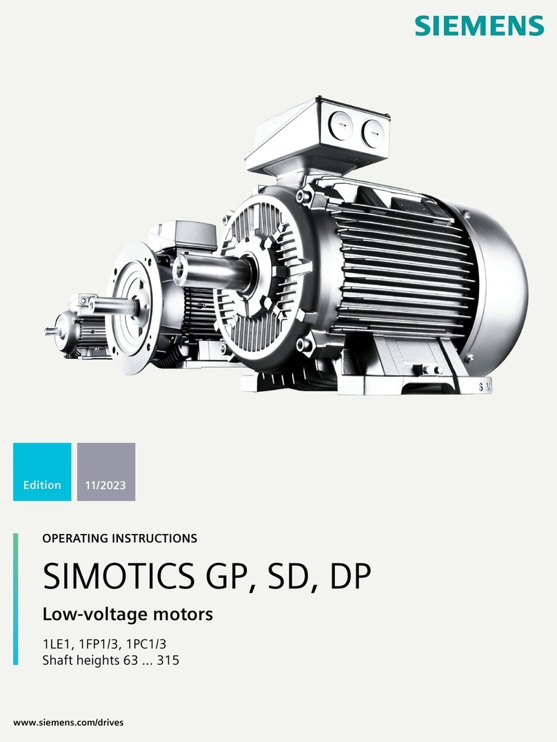
1MB1.33 Eagle Line shaft heights 71 ... 315
Operating Instructions, 08/2023, A5E52990459A 5
4.14.6 Speed limits for converter operation .................................................................................. 63
5 Assembly.............................................................................................................................................. 65
5.1 Safety instructions for installation ...................................................................................... 65
5.2 Preparing for installation.................................................................................................... 66
5.2.1 Requirements for installation ............................................................................................. 66
5.2.2 Insulation resistance .......................................................................................................... 67
5.2.2.1 Insulation resistance and polarization index ....................................................................... 67
5.2.2.2 Checking the insulation resistance and polarization index of the winding ........................... 68
5.3 Mounting and installed the machine .................................................................................. 71
5.3.1 Preparing the assembly area .............................................................................................. 71
5.3.2 Lift the machine to where it will be mounted and position it............................................... 71
5.3.3 Machines with type of construction IM B15, IM B9, IM V8 and IM V9................................... 72
5.3.4 Foot mounting................................................................................................................... 72
5.4 Alignment and fastening.................................................................................................... 73
5.4.1 Repainting/touching up the paint finish of explosion-protected machines ........................... 73
5.4.2 Measures for alignment and mounting............................................................................... 74
5.4.3 Flatness of the supporting surfaces for conventional motors............................................... 74
5.4.4 Machine frame mounting feet (special design)................................................................... 75
5.5 Installing the machine ....................................................................................................... 75
5.5.1 Preconditions for smooth, vibration-free operation............................................................. 75
5.5.2 Aligning the machine to the driven machine and mounting................................................ 75
5.5.2.1 Type of construction without flange................................................................................... 75
5.5.2.2 Horizontal types of construction with mounting feet .......................................................... 75
5.5.2.3 Horizontal types of construction with flange ...................................................................... 76
5.5.2.4 Vertical types of construction with flange........................................................................... 77
5.5.3 Removing the rotor shipping brace..................................................................................... 77
5.5.4 Recommended alignment accuracy .................................................................................... 78
5.5.5 Mounting the drive output elements.................................................................................. 78
6 Electrical connection ........................................................................................................................... 83
6.1 Connecting the machine .................................................................................................... 84
6.1.1 Safe connection................................................................................................................. 84
6.1.2 Selecting cables................................................................................................................. 85
6.1.3 Thermal protection ............................................................................................................ 85
6.1.4 Terminal box ..................................................................................................................... 86
6.1.4.1 Circuit diagram inside the terminal box cover..................................................................... 86
6.1.4.2 Direction of rotation .......................................................................................................... 86
6.1.4.3 Terminal marking .............................................................................................................. 87
6.1.4.4 Additional bores in the terminal box
................................................................................... 87
6.1.4.5 Cable entry........................................................................................................................ 87
6.1.4.6 Protruding connection cables............................................................................................. 88
6.1.4.7 Connecting protruding cables ............................................................................................ 89
6.1.4.8 Thread sizes in the terminal box......................................................................................... 89
6.1.4.9 Internal equipotential bonding........................................................................................... 89
6.1.5 Cable glands...................................................................................................................... 90
6.1.5.1 Mounting position of sheet metal nuts in screw-type connections ...................................... 90
6.2 Tightening torques ............................................................................................................ 91
6.3 Connecting the grounding conductor................................................................................. 91
