Vmetro VBT-325 Series User manual

Artisan Technology Group is your source for quality
new and certied-used/pre-owned equipment
• FAST SHIPPING AND
DELIVERY
• TENS OF THOUSANDS OF
IN-STOCK ITEMS
• EQUIPMENT DEMOS
• HUNDREDS OF
MANUFACTURERS
SUPPORTED
• LEASING/MONTHLY
RENTALS
• ITAR CERTIFIED
SECURE ASSET SOLUTIONS
SERVICE CENTER REPAIRS
Experienced engineers and technicians on staff
at our full-service, in-house repair center
WE BUY USED EQUIPMENT
Sell your excess, underutilized, and idle used equipment
We also offer credit for buy-backs and trade-ins
www.artisantg.com/WeBuyEquipment
REMOTE INSPECTION
Remotely inspect equipment before purchasing with
our interactive website at www.instraview.com
LOOKING FOR MORE INFORMATION?
Visit us on the web at www.artisantg.com for more
information on price quotations, drivers, technical
specications, manuals, and documentation
Contact us: (888) 88-SOURCE | sales@artisantg.com | www.artisantg.com
SM
View
Instra

User's Manual
VBT-325
Including VBAT-PB
Rev. 1.4 - Valid for Firmware Version 4.99.120
VBT-325B VMEbus Analyzer
VBT-325C VMEbus & VSB/SCSI/P2 Analyzer
VBAT-PB VMEbus Anomaly Trigger Piggyback module
Related documents:
S/TIM200-PB 200MHz Timing Analyzer and Stimuli / Pattern
Generator Piggyback module

Warranty
VMETRO products are warranted against defective materials and workmanship
within the warranty period of 1 (one) year from date of invoice. Within the warranty
period, VMETRO will, free of charge, repair or replace any defective unit covered by this
warranty, shipping prepaid. A Return Authorization Code should be obtained from
VMETRO prior to return of any defective product. With any returned product, a written
description of the nature of malfunction should be enclosed.
This warranty assumes normal use. Products subjected to unreasonably rough
handling, negligence, abnormal voltages, abrasion, unauthorized parts replacements and
repairs, or theft are not covered by this warranty and will be repaired for time and
material charges in effect at the time of repair.
VMETRO's warranty is limited to the repair or replacement policy described above
and neither VMETRO nor its agent shall be responsible for consequential or special
damages related to the use of their products.
USA:
Europe, Asia:
VMETRO, Inc.
16010 Barker's Point Ln, #575.
Houston, TX 77079, U.S.A.
Tel.: (713) 584-0728
Fax: (713) 584-9034
VMETRO NS
Nedre Rommen 5E
N-0988 OSLO, Norway
Tel.: +47 22 10 60 90
Fax: +47 22 10 62 02
ii

Preface
Notes - Firmware version 4.99.120
This version of the User's Manual is written for the firmware version 4.99.120.
VMETRO is continuously updating the firmware for the VBT-325 and
piggybacks, implementing new features and improvements.
The main features to be provided in upcoming firmware releases are:
•Timing markers in waveform diagrams.
•Ability to show trace windows from VME and/or P2 and/or TIM200 at
the same time.
Note:
•Ability to dump/load "Setups" to/from files on a PC/Host.
•User-defined P2 support, allowing customized definition of signal
names, allocation and groups etc. for the P2 bus.
Apreliminary version of User-defined P2 is available upon request.
Please contact VMETRO for more information.
These features and more will come in subsequent firmware releases which will
be sent to all VBT-325 customers un-requested and free of charge.
iii

The Bus Analyzer concept
ABus Analyzer is a pre-configured logic analyzer designed as a plug-in card for a
specific bus, conforming to the electrical and mechanical specification of the target bus.
The primary use of a Bus Analyzer is to monitor the activity on a backplane bus and
provide a trace of bus cycles between modules on the bus, presenting this as alphanumeric
trace lists or as waveforms on a standard ASCII terminal. This is done without the need for
connecting and configuring large numbers of probes to the backplane, a time-consuming
and error-prone process necessary with general-purpose logic analyzers. Statistics analysis
in bus systems is also an important application of bus analyzers.
Abasic idea behind bus analyzers is that the analyzer is "hard-wired" to capture the
protocol of the target bus, thereby reducing the need for the user to understand all the
details of the bus protocol in order to perform meaningful analysis of activity in the target
system. This offers the user maximum productivity and convenience during development,
debugging, testing and verification of bus based computer systems.
VMETRO is a company totally committed to building the finest Bus Analyzers, and
is recognized in development labs around the world as providing superior tools for
developers and manufacturers of bus based computer equipment. With the VBT-325,
VMETRO offers the fourth generation, state-of-the art product based on 10 years of
experience in building bus analyzers.
UM ETRO
The Bus Analyzer Specialist
iv
TABLE OF CONTENTS
TABLE OF CONTENTS
1VBT-325 PRODUCT OVERVIEW1
Main blocks 1
Model B and C2
Applications4
Specification Highlights4
Piggyback modules5
Piggyback Carrier (VPC-MkII)6
Piggyback User's Manuals6
VBAT-PB6
S/TIM200-PB6
VDRIVE-PB6
Accessories7
2INSTALLATION9
Static electricity - Precautions9
Preparations10
Inspection10
Jumper settings10
P2 rows A/C connections11
TTL/CMOS Input only (0-5V)11
Isolation of P2 rows a/c11
Slot Selection12
VMEbus12
VSB12
Daisy-Chains12
Slot 112
User-defined P213
Power supply14
Air Cooling14
5V readout14
+/-12V15
External Power15
Terminal Connection17
Transparent mode .19
Terminal-Host RS232 handshake19
Power-On20
Automatic Baud Rate detection20
Start-up menu21
Select Terminal type (T)21
PC as terminal22
<CR> = Continue22
Clear Non-volatile memory22
3FUNCTIONAL DESCRIPTION23
Main blocks23
Sampling stage24
State (Synchronous) sampling25
Timing (Asynchronous) sampling25
Word Recognition / Triggering stage25
Sequencer27
Sample Storage stage27
Trace Buffer27
Trigger position27
Statistics Counters28
Sampling methods29
VMEbus state sampling29
Bus Request latching29
Bus Grant latching - BgL29
Data cycle sampling30
IRQ -> IACK30
RMW, Block30
VME6431
SSB LT31
VSB state sampling31
SCSI state sampling32
SCSI Pinout33
SCSI-2 FAST33
VXI sampling33
User-defined P2 state sampling33
External inputs34
In3:0 in VME part34
In3:0 to P2 part using cross trigger34
Shared In3:0 and Time Tag bits34
Shared Inl and Temperature Probe34
4OPERATION35
User-interface structure35
Targ ets 35
Screen categories36
Setup screen37
Trace Display screen37
Statistics screen37
vi
Screen and Command elements37
Pull down menus37
Sub-command selection38
Accelerator keys38
Dialog Boxes39
Function keys40
Numeric keypad41
Keyboard template41
Multiple windows41
Message line42
Block Cursor recommended42
Refresh Screen42
Event Patterns42
Control signals43
Signal groups with mnemonics43
NOT operator43
Individual signals44
Signal polarity44
Edit event patterns45
Delete fields/event patterns45
Insert signal fields45
Insert event patterns46
Horizontal scrolling46
BR* and IRQ* format47
Address/Data attributes47
Binary details47
Not47
64-bit47
Range48
Sequencer48
General structure of one state49
Single event and Sequencer modes50
Single Event mode50
Sequencer mode50
Event Expression50
Sequencer Notation51
UPPER/lower case51
Use of brackets51
State and Line numbers51
Indents51
Input indicators51
Change event52
Modify the sequencer program53
Operators53
Sampling53
Store54
If/Elsif/Else54
vii

Goto55
Count55
Delay55
Trigger56
Halt56
Implicit actions and transitions56
Loose and Tight sequence57
Sequencer examples58
Count, Delay and Switch sampling mode58
VSB sequencer examples59
Cross-triggering62
Trace Display63
Alphanumeric trace list63
Signal selection64
Horizontal scrolling64
Waveforms64
Hex/Binary value65
Signal selection65
Zooming (Time/Div)65
Add window66
Trace Dump to PC/Host66
Simulator used for trace review66
Statistics 66
Statistics screen67
Display features68
Time History Diagram69
Counters Operation70
Update rate71
Accumulate/Reset mode71
Idle interval72
Event Counting / Bus Level Histogram72
Bus Utilization Histogram73
VMEbus Utilization measurements74
VSB Utilization measurements75
Bus Transfer Rate Histogram76
5EXAMPLE OF USE77
Setting trigger78
Event Patterns78
Edit a signal field78
Single Event Mode79
The Sequencer79
Edit the Sequencer79
Start Sampling79
To take a VMEbus trace79
To trace another bus80
viii

Trace Multiple busses80
Trace Display Screen80
Time Tags80
Jump81
Search81
Add a trace window81
Timing sampling81
Statistics 81
Piggybacks82
6COMMANDS REFERENCE83
Main menu - Setup screen83
Trace83
-Run VME83
-Run Multiple83
-Sampling Status83
- Halt VME84
-Show85
Edit85
-Event Patterns85
-Sequencer85
-Trigger position86
-Sampling mode86
-Options / State Sampling options86
Target87
-VME87
-P2 bus88
-TIM200 bus88
- STIM200 bus88
-Reconfigure88
Statistics88
Setups88
-Initialize89
-Store89
-Delete89
Utilities89
-Transparent Mode89
-Transparent Mode Options89
- Trigger Output Options90
-LED Display90
[X] Voltage readout90
[X] Temperature readout91
-Serial Ports92
-Selftest92
-Reset Analyzer92
-Specials92
ix

Help92
Trace Display menu93
Trace93
-Dump to PC93
-Load from PC93
- Print93
Search94
- Find94
- Extract Mode95
-Close Search Window95
Jump95
- First Line95
- Last Line95
-Trigger Line95
- Line number95
Count96
Format96
-Time/Div96
-Absolute/Relative Time tags96
-Decoding and Formatting96
-ASCII Decoding96
-Trace signals96
-Global options97
Window97
- New97
-Close97
Quit97
Help97
Statistics menu98
Session98
-Run98
-Continue98
-Halt98
Function98
-Event Counting98
-Bus Utilization (VME and VSB)99
-Bus Transfer Rate (VMEbus only)99
Options99
-Standard Histograms vs. Time History Curves99
- Bar Markers99
-Graph Display Options100
-Maximum Scale100
-Count Options100
-Select Events101
Target102
-VME102
-P2 bus102
x

Utilities102
Quit102
Help102
7SIGNAL REFERENCE103
VMEbus Signal Groups103
VMEbus Signals104
Other signals - Target VME104
VSB Signal Groups105
VSB Signals105
Other signals - Target VSB106
8TRACE EXAMPLES107
VMEbus107
VSB108
SCSI109
9VBAT-PB VME BUS ANOMALY TRIGGER111
VBAT-PB Product Overview111
Finds incompatibilities111
Example of violation found112
Mask violations112
Complements the VBT-325113
Related documents113
VBAT-PB Features114
VBAT-PB Specifications115
Violations screened for115
Non violations indicated116
Trigger characteristics116
Power requirements117
Possibilities and limitations117
What the VBAT can do117
What the VBAT cannot do117
Arbiter location118
Onboard Arbiter118
VBAT-PB Installation119
VBAT-PB Operation120
VBAT-to-VBT trigger signal120
VBAT command screen121
The Violations command121
Enable121
xi

Disable122
Clear122
The Mask command122
Select122
Select All122
Select None122
The Modes command122
Manual and Automatic clear122
Lock on first123
Accumulate123
Black Cockpit123
High intensity and Inverse video124
Explain violation124
Violation descriptions125
VBAT-PB Switch settings 130
Arbiter Enable/Disable130
Trigger Output Signals130
Front panel Trig output130
ERROR output on VBAT130
Individual trigger outputs130
10 VBT-325 FIRMWARE UPGRADE PROCEDURE132
Diskette for PCs132
Boot PROM132
RS232 connection132
Load firmware from PC133
Specify PCB and ECO Level133
Setups lost134
Procedure if Boot PROM is missing or wrong version134
Run from Boot PROM136
11 JUMPER SETTINGS137
VME & VSB (Twin mode)139
VSB Bus Grant Daisy chain jumper139
VME & SCSI (Twin mode)141
VME & User-defined P2 (Twin mode)143
Futurebus+ (Wide mode)143
12 SCSI CONNECTION ON P2145
VBT-325 SCSI P2 adapter146
SCSI Connection on P2147
xii
13 CUSTOMIZED ISOLATION OF P2A/C149
14 VMETRO VT100 EMULATOR - VT100.EXE151
Usable "terminal types"152
Built-in script language152
Script control commands153
Function keys in script files154
15 DUMP/LOAD OF TRACE TO/FROM PC155
Dump to PC/Host Command155
Comments156
From line156
To line156
Packing156
Load From PC/Host Command157
Insert from line157
Initialize non-loaded trace lines 157
Dump/Load Trace using the WINDOWS Terminal Emulator158
Dump Trace using VMETRO VT100 Emulator158
Load Trace using VMETRO VT100 Emulator158
Dump/Load with PROCOMM-PLUS159
Trace File Format160
16 SIMULATOR FOR PC163
Demonstration / training163
Reviewing trace files163
Creating patterns164
Simulate bus activity164
Trace Files164
INDEX167

xiv
1
1
I
1
1
I
I
i
i
I
I
1
I
I
1
I
1
I
I

1VBT-325 PRODUCT OVERVIEW
The VBT-325 "VME+ Analyzer" is a bus analyzer for VME and VSB, SCSI or
other P2 busses, e.g. the TTL level signals on P2a/c on VXI (when used with
an VXE-35C adapter). The board contains two separate independent analyzers,
one 128-bit wide analyzer pre-configured for the VMEbus, and one 64-bit wide
analyzer that can be configured either for VSB, SCSI or other busses on the P2
connector of VME boards. Both analyzers on the board have individual
sampling logic, word recognizers, trace memories and triggering circuitry. An
onboard 68ECO20 microprocessor with 512KByte of Flash EPROMs controls
the hardware and runs the user-interface, which is operated from an ASCII
terminal, PC or workstation through a RS232 port.
Main blocks
Each analyzer part of the VBT-325 consists of three main stages, through
which samples are passing during the acquisition process:
•Sampling stage
•Word Recognition / Triggering stage
•Sample Storage / Statistics Counting stage
Ext. 4
inputs
Trigger
Output
Terminal<_÷
Host /
Printer 1E--->
VMEbus
Time
Tag
Sampling 51
registers
4x Word
Recognizers
(Trace Butter
(128x32K)
Clock
generation
Trigger
Sequencer
Statistics
counters
Cross
Trigger
P2 rows a/c
lime
Tag
VSB SCSI Us(
Clock sel.
jumpers I
4x Word
Recognizers
(Trace Buffer
(64x3
Figure 1. VBT-325 Block Diagram (shown in "Twin mode")
Clock
generation
Trigger
Sequencer
Statistics
counters
VMETRO VBT-325 User's Manual 1

1VBT-325 Product overview
As can be seen from the block diagram in figure 1, the VBT-325 contains
substantial amount of hardware functionality. This is achieved through six
advanced ASICs designed and developed by VMETRO called the Bus Tracer
Chip (BTC). These devices implement all the sample acquisition, recognition
and storage capabilities of the board, as well as numerous counters for statistics
and time measurements. This gives the VBT-325 remarkable performance and
functionality, like sampling rate up to 50MHz in state or timing mode,
advanced triggers with Not and Range capabilities, as well as store filters and
occurrence and delay counters.
The chapter FUNCTIONAL DESCRIPTION later in this manual gives more
details of the functions of the different blocks in the product.
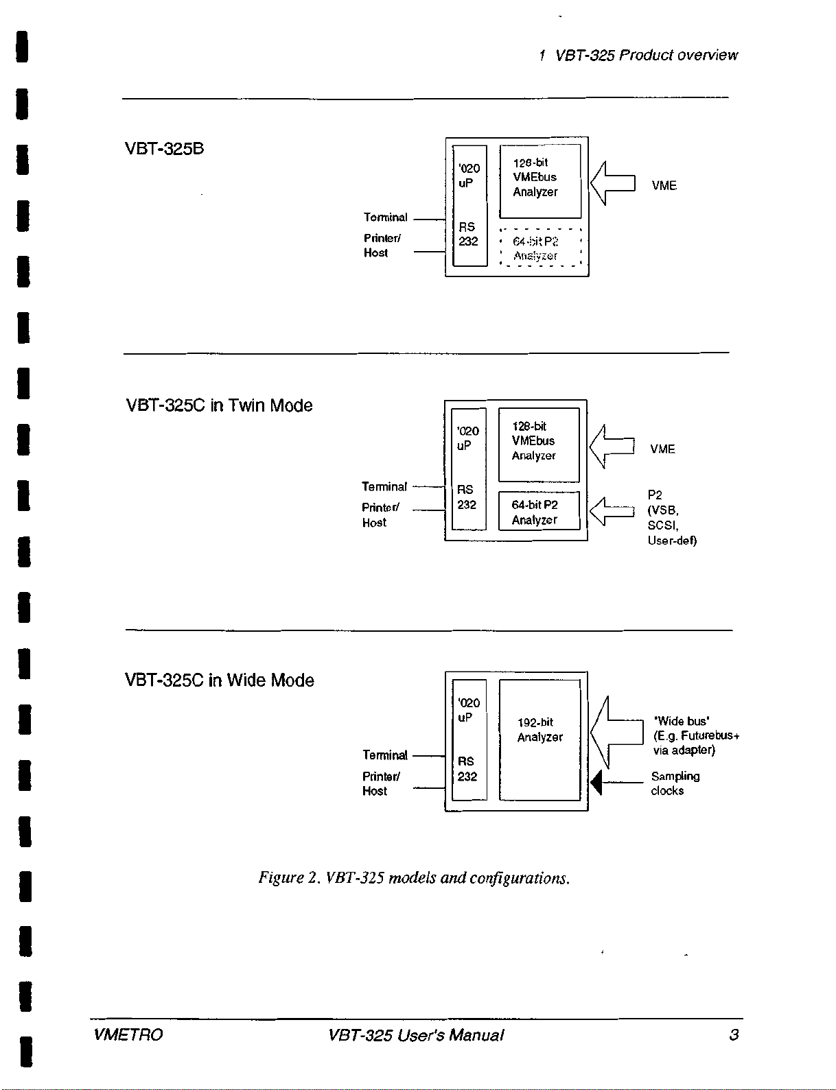
Model B and C
The VBT-325 is available in two models, VBT-325B and VBT-325C. Model
VBT-325C is the full-featured version that supports both VMEbus and VSB/
SCSI/P2, with upgradeability to other busses like VXI and Futurebus+. The
VBT-325B is a lower-cost version, where only the VMEbus is supported, but
otherwise with the same performance as the VBT-325C. The VBT-325B can
easily be upgraded, in the field, to a VBT-325C by means of a firmware/PLD
upgrade.
2VBT-325 User's Manual VMETRO
1VBT-325 Product overview
VBT-325B
'020
uP
128-bit
VMEbus
Analyzer VME
Terminal RS
Printer/ 232 64 •Nt P2
Arla;yzc:r
Host
VBT-325C in Twin Mode
Terminal
VME
'020
uP
128-bit
VMEbus
Analyzer
RS P2
Printer/ 232 64-bit P2
Analyzer (VSB,
SCSI,
Host
Use r-def)
'020
uP 192-bit
Analyzer
RS
232
VBT-325C in Wide Mode
Terminal
Printer/
Host
Figure 2. VBT-325 models and configurations.
'Wide bus'
(E.g. Futurebus+
via adapter)
Sampling
clocks
VMETRO VBT-325 User's Manual 3

1VBT-325 Product overview
Applications
Applications of the VBT-325 include hardware and software debugging and
testing, system tuning, and performance analysis. Other applications are repair
and field service of a number of different bus architectures, primarily VMEbus,
with or without subsystem busses like VSB, SCSI, user defined P2 bus and
VXI or Futurebus+ with the use of specially designed adapters.
Working with the product involves utilizing one of three basic analyzing
capabilities:
•State analysis (capturing bus cycles synchronously one by one).
•Timing analysis (capturing bus cycles at a fixed sampling rate
asynchronously to the bus traffic).
•Statistical analysis (providing histograms of various bus activity).
Specification Highlights
VBT-325C:
•32K Trace memory, separate for VME and P2.
•101 ch. VMEbus Analysis, plus 4 ext. inputs on mini-coax
•64 ch. VSB/SCSI/P2 Analysis with separate trigger sequencer.
•Simultaneous VME and VSB/SCSI/P2 analysis with cross-
triggering and integrated user-interface.
•50MHz Timing Analysis on VME and VSB/SCSI/P2.
•State Analysis up to 25MHz on VME and VSB/SCSI/P2,
up to 50MHz on Futurebus+ with full-speed trigger.
•VMEbus rev.D compatible, incl. VME64 and SSBLT sampling.
•Voltage, Temperature monitoring and Time-of-Day clock.
VBT-325B:
•As VBT-325C, but without P2 support. Field upgradeable to VBT-
325C by firmware/PLD replacement.
4VBT-325 User's Manual VMETRO

1VBT-325 Product overview
Piggyback modules
TIM200-PB
STIM200-PB
VDRIVE-PB
VBAT-PB
The VBT-325B/C is equipped with
connectors that allow it to carry piggyback
modules for added functionality or
performance. Below is a short presentation of
the piggyback modules currently available for
the VBT-325.
The TIM200-PB is a 200MHz Timing
Analyzer piggyback module for the VBT-325
for high-speed analysis of the VMEbus or P2
bus. The TIM200-PB has a 32K trace buffer
and samples up to 107 signals with 5ns
resolution, and offers full-speed trigger on
any bit or bit combination, including cross-
trigger from the VBT-325. The trigger
pattern can be qualified with a "duration filter", to specify valid pattern as
greater than or less than in the range 5-635ns. Signals sampled are presented as
graphical waveforms with zoom, cursors and timing markers. The TIM200-PB
can be upgraded to a STIM200-PB, see below.
The STIM200-PB is a 200MHz stimuli/pattem generator piggyback module for
the VBT-325. It is essentially a TIM200-PB with firmware that permits its trace
memory to be put in reverse. The STIM200-PB can generate bus cycles on
VME or VSB and has user-defined timing with 5ns edge-to-edge resolution, as
well as, true bus grant and slave handshake. By means of a screen-oriented
pattern editor the user may create any type of cycles and signal sequences.
Cycle templates are also provided that include all VMEbus cycles, including
VME64 and SSBLT 64-bit block cycles.
The VDRIVE-PB is a piggyback module that implements a true VMEbus
Master/Slave and System Controller by means of the industry standard VIC068
chip. From the same user-interface as that of the VBT-325, the user can then
generate any cycle type, perform memory tests, and generate interrupts, IACKs
etc. The slave memory can also be set at user-defined limits, and there is a
programmable DTACK* generator that can give DTACK* at any address with
auser-defined delay.
The VBAT-PB is a piggyback module that automatically monitors all VMEbus
traffic, screening the bus for violations of the VME specification. The board's
rule-based parallel trigger elements continuously, and simultaneously, detect
bus timing violations like address not stable while AS* asserted, bus granted to
two masters, etc. Violations are directed to the trigger circuitry and trace
memory of the VBT-325, and the rule violations are explained in plain English.
VMETRO VBT-325 User's Manual 5
This manual suits for next models
3
Table of contents
Other Vmetro Measuring Instrument manuals


