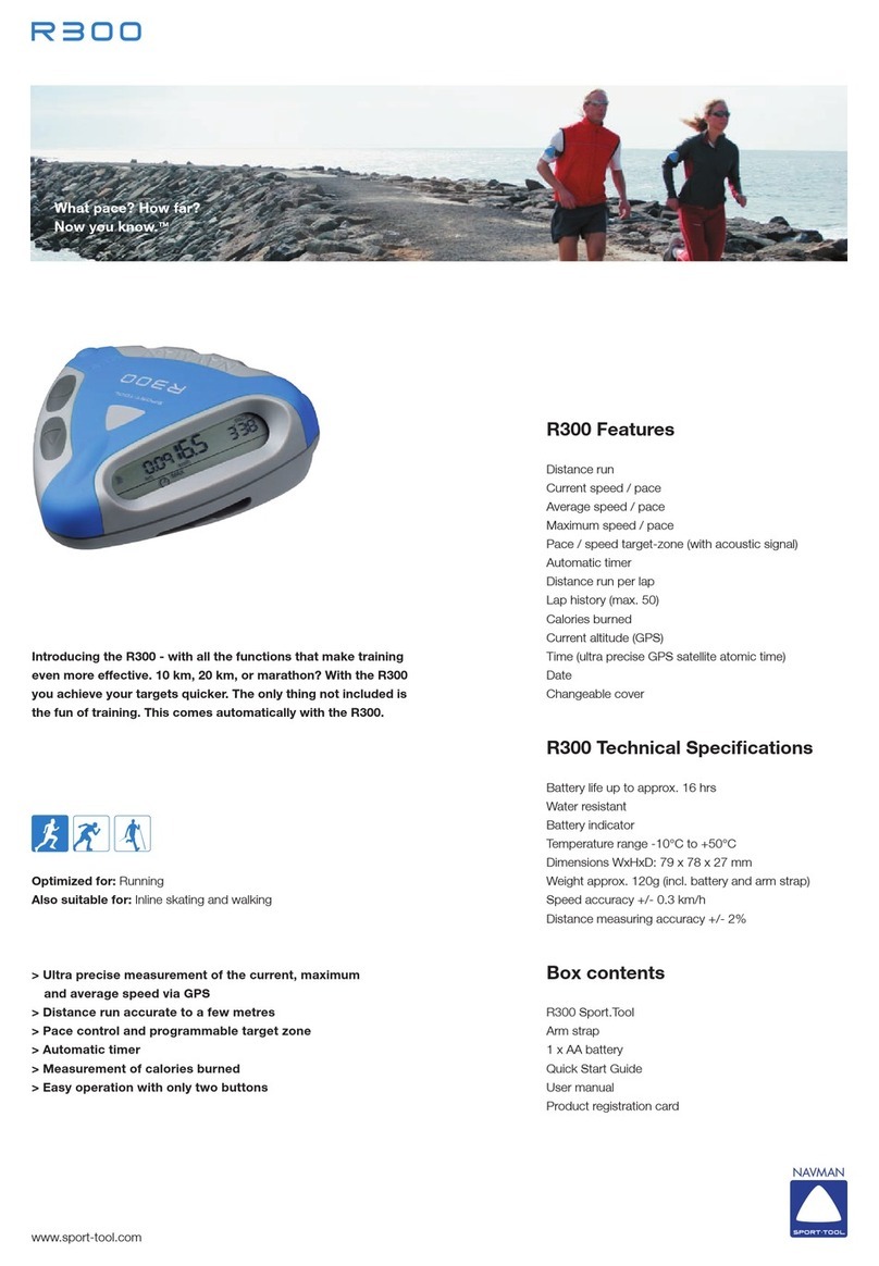
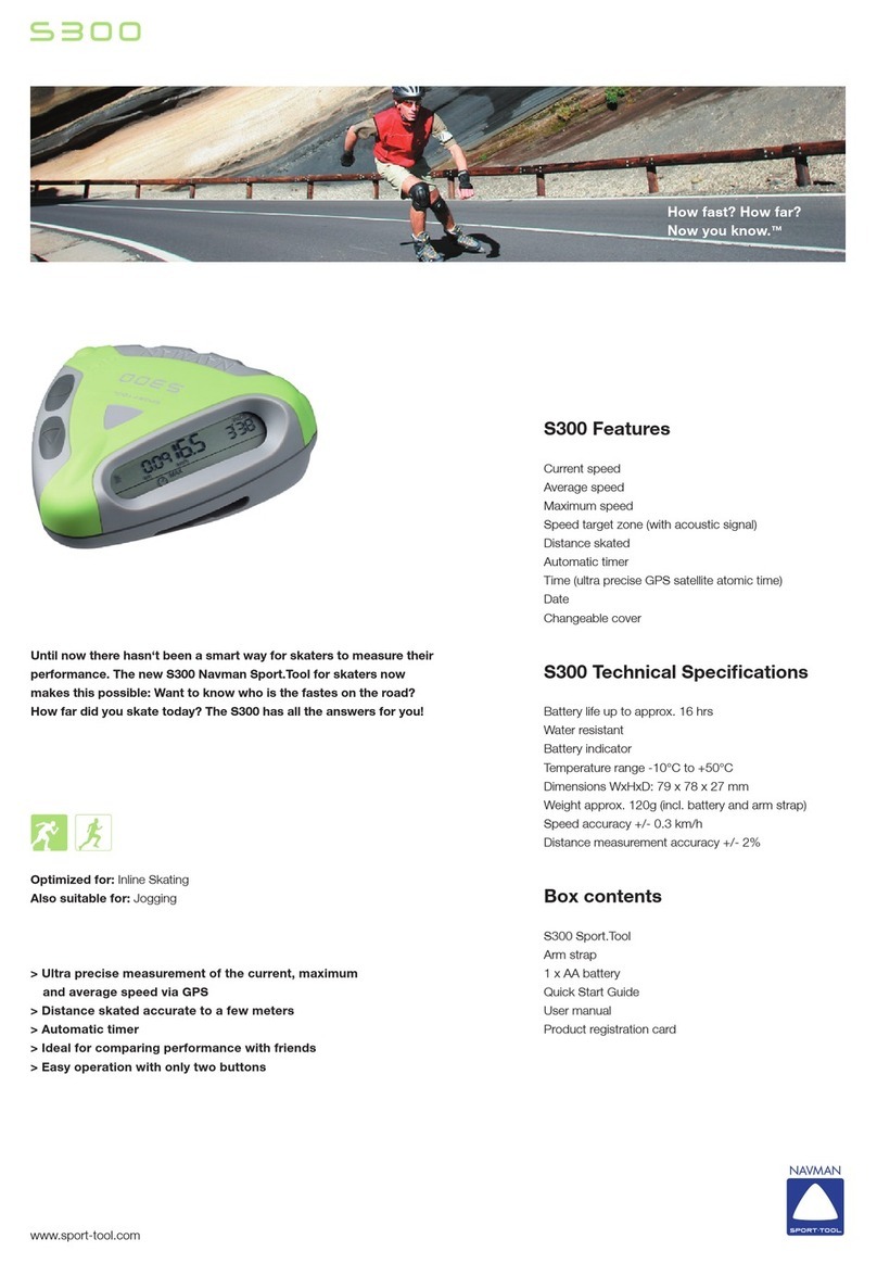
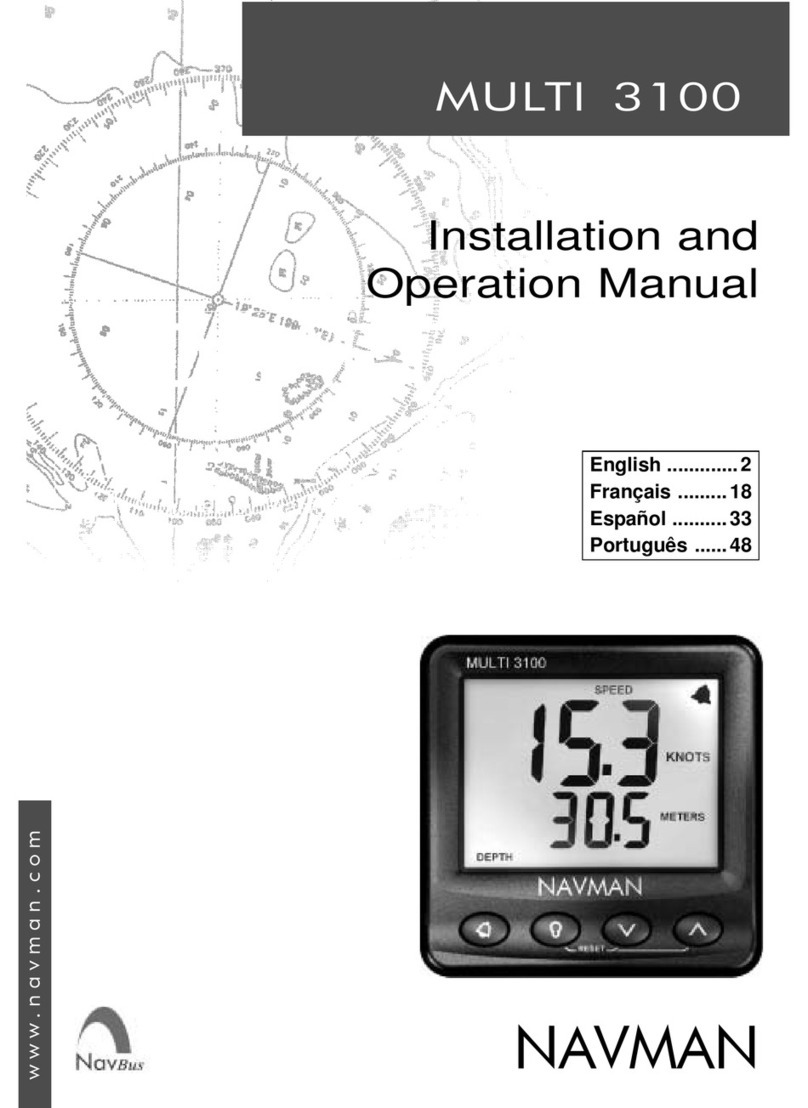
Navman MULTI 100 User manual

MULTI
RESET
NAVMAN
NAVMAN

5NAVMAN M100UserManual
Contents
Specification . . . . . . . . . . . . . . . . . . . . . . . . . . . . . . . . . . . . . . . . . . . . . . . . . . . . . . . . . 6
Installation . . . . . . . . . . . . . . . . . . . . . . . . . . . . . . . . . . . . . . . . . . . . . . . . . . . . . . . . . . . 7
Location . . . . . . . . . . . . . . . . . . . . . . . . . . . . . . . . . . . . . . . . . . . . . . . . . . . . . . . . . . 7
Mounting . . . . . . . . . . . . . . . . . . . . . . . . . . . . . . . . . . . . . . . . . . . . . . . . . . . . . . . . . . 7
Wiring Connection . . . . . . . . . . . . . . . . . . . . . . . . . . . . . . . . . . . . . . . . . . . . . . . . . . 8
Multiple Instruments . . . . . . . . . . . . . . . . . . . . . . . . . . . . . . . . . . . . . . . . . . . . . . . . . 8
Operation . . . . . . . . . . . . . . . . . . . . . . . . . . . . . . . . . . . . . . . . . . . . . . . . . . . . . . . . . . . . 9
Changing Functions . . . . . . . . . . . . . . . . . . . . . . . . . . . . . . . . . . . . . . . . . . . . . . . . . 9
The Depth Alarms . . . . . . . . . . . . . . . . . . . . . . . . . . . . . . . . . . . . . . . . . . . . . . . . . . 10
Setting Alarms. . . . . . . . . . . . . . . . . . . . . . . . . . . . . . . . . . . . . . . . . . . . . . . . . . . . . 10
Set Shallow Alarm . . . . . . . . . . . . . . . . . . . . . . . . . . . . . . . . . . . . . . . . . . . . . . . . . 10
Set Deep Alarm. . . . . . . . . . . . . . . . . . . . . . . . . . . . . . . . . . . . . . . . . . . . . . . . . . . . 10
Select Temperature Units . . . . . . . . . . . . . . . . . . . . . . . . . . . . . . . . . . . . . . . . . . . . 10
Select Depth Units . . . . . . . . . . . . . . . . . . . . . . . . . . . . . . . . . . . . . . . . . . . . . . . . . 10
Timer Functions . . . . . . . . . . . . . . . . . . . . . . . . . . . . . . . . . . . . . . . . . . . . . . . . . . . 11
Elapsed Timer . . . . . . . . . . . . . . . . . . . . . . . . . . . . . . . . . . . . . . . . . . . . . . . . . . . . . 11
Count Down Timer . . . . . . . . . . . . . . . . . . . . . . . . . . . . . . . . . . . . . . . . . . . . . . . . . 11
Select Speed/Log Units . . . . . . . . . . . . . . . . . . . . . . . . . . . . . . . . . . . . . . . . . . . . . 12
Reset Log (Trip Distance) . . . . . . . . . . . . . . . . . . . . . . . . . . . . . . . . . . . . . . . . . . . . 12
Reset Total Log (Total Distance). . . . . . . . . . . . . . . . . . . . . . . . . . . . . . . . . . . . . . . 12
Reset Average Speed . . . . . . . . . . . . . . . . . . . . . . . . . . . . . . . . . . . . . . . . . . . . . . 12
Reset Max Speed . . . . . . . . . . . . . . . . . . . . . . . . . . . . . . . . . . . . . . . . . . . . . . . . . . 12
Backlighting On / Off . . . . . . . . . . . . . . . . . . . . . . . . . . . . . . . . . . . . . . . . . . . . . . . . 12
Simulation Mode . . . . . . . . . . . . . . . . . . . . . . . . . . . . . . . . . . . . . . . . . . . . . . . . . . . 12
Secondary Functions . . . . . . . . . . . . . . . . . . . . . . . . . . . . . . . . . . . . . . . . . . . . . . . . . 13
Calibration Procedures . . . . . . . . . . . . . . . . . . . . . . . . . . . . . . . . . . . . . . . . . . . . . . . 14
Keel Offset. . . . . . . . . . . . . . . . . . . . . . . . . . . . . . . . . . . . . . . . . . . . . . . . . . . . . . . . 14
Transducer Setting . . . . . . . . . . . . . . . . . . . . . . . . . . . . . . . . . . . . . . . . . . . . . . . . . 14
Calibrate Temperature Display . . . . . . . . . . . . . . . . . . . . . . . . . . . . . . . . . . . . . . . . 14
Speed Calibration . . . . . . . . . . . . . . . . . . . . . . . . . . . . . . . . . . . . . . . . . . . . . . . . . . . . 15
Speed Comparison Method . . . . . . . . . . . . . . . . . . . . . . . . . . . . . . . . . . . . . . . . . . 15
Log Calibration Method . . . . . . . . . . . . . . . . . . . . . . . . . . . . . . . . . . . . . . . . . . . . . 15
Troubleshooting Chart . . . . . . . . . . . . . . . . . . . . . . . . . . . . . . . . . . . . . . . . . . . . . . . . 16
M100/ENG/1D

6NAVMAN M100User Manual
Specification
• Power Supply
10.7 to 16.6 VDC, 90 mA nominal, 100 mA
with backlights on full.
• Operating temperature
0°C to 45°C.
• Size of display
112 x 112 x 24mm (4.4 x 4.4 x 1”), overall
depth 35mm (1.4”) behind panel.
• Display type.
Twisted Nematic (TN) grey background.
• Illumination
Red LED switchable from key pad.
• RF interference
Neglible interference on any VHF marine radio
channel with 3dB gain antenna at 1 metre
from the instrument display head.
• Depth
1 to 130 metres or 3 to 400ft or 0.5 to 70
fathoms.
• Alarms
Depth shallow and deep. Audio and LCD flag.
• Depth unit selection
Feet, metres or fathoms, key pad selectable.
• Transducer
200 kHz, 600 ohm, 1500pF parallel
capacitance.
• Boat speed
0 to 50 knots or 0 to 90kph or 0 to 60Mph,
may be different for transducers other than
that supplied with instrument. User selectable
to display in 0.1 or 0.01 increments.
• Speed units and resolution
0.00 to 19.90 and then 20 to 50 in knots, Mph
or kph.
RESET
MULTI
LOG
TOTAL
DEPTH
SPEED
AVG
SPEED
DEPTH
Display is backlit for
Night Operation
Multi-function
display
Depth/speed
trend indicators
Sea temperature
Depth/speed
trend indicators
Alarm
indicator
• Maximum speed
Records max. speed to 50 knots. Reset to zero
via key pad or at power down.
• Log (Trip distance)
0 to 99999 units key pad selectable in Kts,
Mph or kph. Shows two decimal places when
value is below 1000. Shows one decimal place
if value is between 1000 and 10000.
• Total log
0 to 99999 units key pad selectable in Kts,
Mph or kph. Shows two decimal places when
value is below 1000.
• Keel Offset
±9.9 ft, ±1.6 fathoms or ±3.0 metres, user
settable. Allows for display of depth below keel
or waterline.
• Trend Indication
Arrows indicate increasing or decreasing depth
and speed trends.
• Time functions
Trip timer to 99 hrs and 59 minutes. Count
down timers in seconds, start selectable from 1
to 10 minutes.
• Water temperature
0.0°C to 37.7°C (32.0°F to 99.9°F). Tenths of a
degree are displayed.
• Temperature Sensor
Thermistor, 10k ohm at 25°C.
• Output data
NMEA 0183 format. VHW, VLW, MTW, DBT,
DPT.
• Transducer input cables
Phono connector for depth, 4 pin Fuji for
speed/temp transducer. 3 conductor cable for
NMEA and power.
7NAVMAN M100User Manual
Installation
Location
The NAVMAN M100 is designed for above or
below deck installation. Select a position that is:
• At least 300mm from a compass
• At least 500mm from any radio
• Easy to read by the helmsman and crew
• Protected from physical damage
• Accessible to electrical cable connections
• Protected from water spray reaching rear
of instrument.
Mounting
The mounting surface must be flat. Use the
template to set the centre of the fixing hole.
• Drill a 32mm (1.25”) diameter mounting hole
through the bulkhead.
• Remove the fixing nut. Peel the protective
paper off the foam gasket and attach the
gasket to the rear of the instrument.
• Insert the instrument through the bulkhead.
Hand tighten the nut and then finally tighten
with a spanner. Do not over tighten so that
the water sealing ability of the gasket is
damaged.
112mm
(4.4”)
4.5mm
(1.75”)
30mm
(1.2”)
112mm
(4.4”)
24mm
(1”)
56mm
(2.2”)
35mm
(1.4”)

8NAVMAN M100User Manual
• Connect the 4 pin Fuji connector to the
Speed and Temperature transducer.
• Connect the RCA phono connector to the
depth transducer cable connector. Do not
cut or shorten the depth transducer cable.
Extension cables are available if the
transducer cable is too short.
• If you are not using a repeater or you do not
intend to provide NMEA data to another
instrument then insulate the bare wire end
of the blue cable.
Wiring Connection
• Keep electrical and transducer cables away
from alternator or other noise generating
electrical cables. Avoid connecting the
instrument to power circuits that share
loads with ignition, alternators, inverters and
radio transmitters. Electrical power supply
connections should always be as short as
possible.
• Connect the red wire to the positive supply
via a 1 amp fuse or a 1 amp circuit breaker.
Connect the black wire to the electrical
ground (negative terminal of battery).
A 1 amp fuse will provide protection for up
to five 100 series instruments.
Multiple Instruments
TheNAVMAN M100 may be usedasanindividual
instrument or connected with a number of other
100 series instruments to the 100 series
repeater or to other instruments accepting
NMEA 0183 data.
Blue
Black
Red 1A Fuse +12 VDC
Ground
NMEA output to repeater
Fuji
Plug &
Socket
Transducers
Speed Depth
Phono
Plug &
Socket

9NAVMAN M100User Manual
Operation
Changing Functions
The upper and lower display sections can be
configured to display depth or speed readings.
The remaining functions are available on either
the upper or lower display only.
The key selects functions available on the
upper display. The selection remains in memory
after power down.
LOG
SPEED
LOG
LOG
AVG
SPEED
SPEED
LOG
DEPTH
LOG
TEMPERATURE
DEPTH
MAXIMUM
SPEED
AVERAGE
SPEED
SPEED
TRIP
DISTANCE
TRIP
DISTANCE
TRIP
DISTANCE
TRIP
DISTANCE
TRIP
DISTANCE
The key selects functions available on the
lower display. The selection remains in memory
after power down.
SPEED
LOG
LOG
TOTAL
DEPTH
TEMPERATURE
TEMPERATURE
TEMPERATURE
TEMPERATURE
DEPTH
TOTAL
DISTANCE
TRIP
DISTANCE
SPEED

10 NAVMAN M100User Manual
Set Deep Alarm
Press the and keys to enter deep alarm
mode.
Use the and keys to set alarm value.
Press the key to exit.
Note:
When units are changed, the alarm
values are automatically recalculated.
Select Temperature Units
When the top section of the display is indicating
temperature, press and hold the key for
three seconds to change the units of measure
between °C and °F.
Select Depth Units
When the top section of the display is indicating
depth, press and hold the key for three
seconds. The new unit of measure will be
displayed for three seconds.
Alternatively, when the bottom section of the
display is indicating depth, press and hold the
key for three seconds. The new unit of
measure will be displayed for three seconds.
Depthunitscan be selected inthefollowing order;
metres, feet and fathoms.
The Depth Alarms
The shallow water alarm sounds when the depth
falls below the selected value. The deep water
alarm sounds when the depth exceeds the
selected value. When an alarm is activated the
beeper will sound continuously and the bell
alarm symbol will flash.
Setting Alarms
Press the key to switch the alarm on or off.
SPEED
DEPTH
SPEED
DEPTH
Set Shallow Alarm
Press the and keys to enter shallow
alarm mode.
Use the and keys to set alarm value.
Press the key to exit.
SPEED
DEPTH

11NAVMAN M100User Manual
Timer Functions
All timer functions are displayed on the lower
section of the display.
Elapsed Timer
The elapsed timer will record time from power
up. Time is displayed in hours and minutes up
to 99 hours and 59 minutes.
Press the key to show elapsed time.
DEPTH
ELAPSED
TIME
Press and hold the and keys for three
seconds while the elapsed timer displayed to
reset the elapsed time to zero.
DEPTH
3 SEC
Count Down Timer
Press the key twice to show the count down
timer. This timer counts down in seconds from a
starting value that can be set in whole minutes
from 1 to 10.
When countdown timer mode is entered the last
startingvalue used isdisplayed. Tostart counting
downfrom this value,press the key.Toselect
a new value to count from, press the key to
scroll through from 1 to 10. When the desired
value is displayed press the key to start it
countingdown. The countdowntimer gives audio
beeps while counting down, giving 4 beeps at 4
minutes, 3 at 3 minutes, 2 at 2 minutes,1 at 1
minute, and finishing with 10 beeps.The beep at
0 seconds is a long beep.
DEPTH
DEPTH
To reset the count down timer, press and hold
the and keys for three seconds while the
countdown timer is displayed. The display will
return to the start value selection.
INCREASEVALUE
START

12 NAVMAN M100User Manual
Backlighting On / Off
Simultaneously press the and keys to
turn the backlight on or off.
LOG
TOTAL
DEPTH
SPEED
AVG
SPEED
DEPTH
LOG
TOTAL
DEPTH
SPEED
AVG
SPEED
DEPTH
Simulation Mode
The NAVMAN M100 has a simulation mode.
To enter this mode, hold down the key and
then switch on the power. The instrument will
remain in this mode even when power is
switched off.
Repeat this procedure to exit simulation mode.
Note:
Settings that are made while in
simulation mode will remain in effect
after returning to normal mode.
Select Speed/Log Units
Speed and distance units can be selected in the
following order; Knots (nautical miles), kph
(kilometres) and Mph (statute miles).
When the top section of the display is indicating
speed, press and hold the key for three
seconds. The new unit of measure will be
displayed for three seconds.
Alternatively, when the bottom section of the
display is indicating speed, press and hold the
key for three seconds. The new unit of
measure will be displayed for three seconds.
Note:
When changing speed/distance units, the
log and the totals are re-calculated to show
the same distance in the new units.
Reset Log (Trip Distance)
With the log displayed, press and hold the
and keys for 3 seconds.
Reset Total Log (Total Distance)
With the total log displayed, press and hold the
and keys for 15 seconds.
Note:
When the total log is reset the trip log
log and average speed are reset also.
Reset Average Speed
With average speed displayed, press and hold
the and keys for 3 seconds.
Reset Max Speed
With max speed displayed, press and hold the
and keys for 3 seconds.
It is possible to display average speed or max
speed and a log value at the same time. In this
situation the LAST function to be selected will be
reset when the and keys are held down.

13NAVMAN M100User Manual
Secondary Functions
The secondary modes provide access to keel offset, transducer setting, calibration of boat speed,
calibration of water temperature and speed display options of 1/10th or 1/100th units.
If no key is pressed for 10 seconds, the instrument will exit secondary mode
and return the display to normal. Changes made to the secondary function
being displayed at this time will not be saved.
TRANSDUCER SETTING
KEEL OFFSET
PRESS KEYS TO
CHANGE VALUE
10 (1/10ths)
100 (1/100ths)
PRESS BOTH KEYSTO
STEP TO NEXT FUNCTION
SPEED CALIBRATION
EXIT TO EXIT ANYTIME
TEMPERATURE
CALIBRATION
SPEED RESOLUTION
PRESS & HOLD FOR
3 SECONDS TO ENTER
SECONDARY MODE

14 NAVMAN M100User Manual
Calibration Procedures
Note:
If the speed and depth readings flash, this
indicates that the calibration values have
been lost. To correct this, check the depth
units, alarm values, keel offset, speed units
and the speed calibration.
Keel Offset
The NAVMAN M100 will normally display the
depth of water below the face of the transducer.
You may introduce a negative keel offset equal
to the distance from the transducer to the bottom
of the keel to display the depth of the water
below the keel. A positive offset equal to the
distance from the waterline to the transducer
can be used to display the total depth from the
water surface to the bottom. This is often called
a waterline offset.
Follow the Secondary Functions chart to reach
Keel Offset mode.
Use the or key to set the required value.
When the required value is displayed press the
key. The value will be stored in memory.
Note:
When the depth units are changed the
keel offset value will automatically be
recalculated and displayed in the new units.
Transducer Setting
Three values of transducer setting can be
selected (1 to 3). A setting of 3 provides the
maximumimmunity to turbulence, surface clutter
and transducer ringing at the expense of shallow
water performance under 4 feet. A setting of 1
enables the M100 to work in water as shallow
as 1.8 feet at an increased susceptibility to
turbulence.Atasettingof2,theM100 will properly
display depths down to 2.9 feet. The default
setting is 2.
To enter the transducer setting into memory and
exit, press the key.
Calibrate Temperature Display
To adjust the temperature displayed.
Follow the Secondary Functions chart to reach
Temperature Calibration mode.
To increase reading press the
112mm
(4.4”)
4.5mm
(1.75”)
30mm
(1.2”)
112mm
(4.4”)
24mm
(1”)
56mm
(2.2”)
35mm
(1.4”)
key.
To decrease reading press the key.
To enter the calibration setting into memory and
exit, press the key.

15NAVMAN M100User Manual
Speed Calibration
Speed Comparison Method
Use the following sequence to adjust the speed
displayed to match that of another craft or the
speed displayed on a GPS receiver.
Follow the Secondary Functions chart to reach
Speed Calibration mode.
To increase reading press the key.
To decrease reading press the key.
To enter the calibration setting into memory and
exit press the key.
Note:
When the speed calibration is adjusted the
trip log and the average speed will be reset.
Log Calibration Method
Set the log to zero and travel a known distance
between two points.
If there is any tidal current,
you should travel the course in both directions
and use twice the known distance. Try to avoid
the situation where the current is flowwing at
right angles to the course, or if this cannot be
avoided, make sure that the boat speed is at
least ten times the speed of the current.
You may calculate a correction factor as follows:
Known distance
correction factor = distance from log
For example, if you have travelled over a known
distance of 1 mile but your log reading is 0.80,
the correction factor is 1.25. Therefore, your
correct boat speed will be the indicated speed
multiplied by 1.25.
Enter the simulation mode by holding down the
key at power up, When speed is selected in
the simulator mode the display will indicate a
fixed calibration speed. With the factory default
calibration this speed will be 10.0 knots.
Follow the Secondary Functions chart to reach
Speed Calibration mode.
Use the to set the displayed speed to the
new value. For our example, assuming we
started with the factory default calibration, this
new speed would be 10.0 x 1.25 which is 12.5
knots.
To enter the calibration setting into memory and
exit press the key.
To exit simulation mode, remove the power and
then hold the key at power up

16 NAVMAN M100User Manual
Troubleshooting Chart
No display: Check DC power connections and DC polarity with voltmeter. Voltage must be
between 10.7 and 16.6 volts.
No speed reading:
1. Remove speed impellor from skin fitting, spin paddlewheel manually and check
for reading.
2. Check for fouling on paddle and skin fitting.
3. Check for break in cable.
Low or high speed reading:
1. Check calibration.
2. Inspect for damage to paddlewheel or fouling of fitting or paddle.
Erratic speed reading:
1. Is there clear water flow over paddlewheel ?
2. Is paddlewheel aligned fore and aft correctly ?
No, or inaccurate temperature reading:
1. Check calibration
2. Check for break in cable.
No depth reading (--) at all depths:
1. Check transducer for growth or multiple coats of paint.
2. Check the transducer cable for cuts and sharp bends.
3. Substitute the transducer with a known good transducer hold it over the side of
the boat into the water and see if instrument functions. This isolates cause of
problem (transducer or instrument).
Erratic depth readings (while moored):
Check transducer for growth or multiple coats of paint.
Erratic depth readings (while underway):
Cavitation (air) under the face of the transducer. Review installation and reinstall
if necessary.
When power is applied display digit counts up or down:
See the section on Simulation Mode.
Erratic readings when engine is running:
1. Reroute power and transducer cables away from ignition wires and battery
cables.
2. Add feed-through filter capacitor on the positive terminal of the ignition coil.
3. Add alternator whine filter to alternator.
4. Replace spark plug wire with resistive type.
Simulation Mode If the speed is not changing and reading around 10kts regardless of boat speed
then the instrument is in simulation mode.
This manual suits for next models
1
Table of contents
Other Navman Measuring Instrument manuals

Navman
Navman S300 User manual

Navman
Navman WIND 3100 User manual

Navman
Navman FUEL 2100 User manual

Navman
Navman WIND 3150 User manual

Navman
Navman MULTI 3100 User manual

Navman
Navman SPEED 2100 User manual

Navman
Navman Repeat 3100 User manual

Navman
Navman A300 Sport.Tool User manual

Navman
Navman Qube 300 User manual

Navman
Navman R300 User manual