VMIC VMIVME-1160A User manual

Artisan Technology Group is your source for quality
new and certied-used/pre-owned equipment
• FAST SHIPPING AND
DELIVERY
• TENS OF THOUSANDS OF
IN-STOCK ITEMS
• EQUIPMENT DEMOS
• HUNDREDS OF
MANUFACTURERS
SUPPORTED
• LEASING/MONTHLY
RENTALS
• ITAR CERTIFIED
SECURE ASSET SOLUTIONS
SERVICE CENTER REPAIRS
Experienced engineers and technicians on staff
at our full-service, in-house repair center
WE BUY USED EQUIPMENT
Sell your excess, underutilized, and idle used equipment
We also offer credit for buy-backs and trade-ins
www.artisantg.com/WeBuyEquipment
REMOTE INSPECTION
Remotely inspect equipment before purchasing with
our interactive website at www.instraview.com
LOOKING FOR MORE INFORMATION?
Visit us on the web at www.artisantg.com for more
information on price quotations, drivers, technical
specications, manuals, and documentation
Contact us: (888) 88-SOURCE | sales@artisantg.com | www.artisantg.com
SM
View
Instra

12090 South Memorial Parkway
Huntsville, Alabama 35803-3308, USA
(256) 880-0444 w(800) 322-3616 wFax: (256) 882-0859
VMIVME-1160A
32-bit Optically Coupled Digital Input
Board with Change-of-State Detection
Product Manual
500-101160-000 Rev. D
Artisan Technology Group - Quality Instrumentation ... Guaranteed | (888) 88-SOURCE | www.artisantg.com

12090 South Memorial Parkway
Huntsville, Alabama 35803-3308, USA
(256) 880-0444 w(800) 322-3616 wFax: (256) 882-0859
Artisan Technology Group - Quality Instrumentation ... Guaranteed | (888) 88-SOURCE | www.artisantg.com

© Copyright 2002. The information in this document has been carefully checked and is believed to be entirely reliable.
While all reasonable efforts to ensure accuracy have been taken in the preparation of this manual, VMIC assumes no
responsibility resulting from omissions or errors in this manual, or from the use of information contained herein.
VMIC reserves the right to make any changes, without notice, to this or any of VMIC’s products to improve reliability,
performance, function, or design.
VMIC does not assume any liability arising out of the application or use of any product or circuit described herein; nor
does VMIC convey any license under its patent rights or the rights of others.
For warranty and repair policies, refer to VMIC’s Standard Conditions of Sale.
AMXbus, BITMODULE, COSMODULE, DMAbus, IOMax, IOWorks Foundation, IOWorks Manager, IOWorks Server,
MAGICWARE, MEGAMODULE, PLC ACCELERATOR (ACCELERATION), Quick Link, RTnet, Soft Logic Link, SRTbus,
TESTCAL, “The Next Generation PLC”, The PLC Connection, TURBOMODULE, UCLIO, UIOD, UPLC, Visual Soft Logic
Control(ler), VMEaccess, VMEbus Access, VMEmanager, VMEmonitor,VMEnet, VMEnet II, and VMEprobe are
trademarks and The I/O Experts, The I/O Systems Experts, The Soft Logic Experts, and The Total Solutions Provider are
service marks of VMIC.
COPYRIGHT AND TRADEMARKS
VMIC
All Rights Reserved
This document shall not be duplicated, nor its contents used for any
purpose, unless granted express written permission from VMIC.
The I/O man figure, IOWorks, IOWorks man figure, UIOC, Visual IOWorks and the VMIC logo are registered
trademarks of VMIC.
ActiveX, Microsoft, Microsoft Access, MS-DOS, Visual Basic, Visual C++, Win32, Windows, Windows NT, and XENIX
are registered trademarks of Microsoft Corporation.
Celeron and MMX are trademarks, and Intel and Pentium are registered trademarks of Intel Corporation.
PICMG and CompactPCI are registered trademarks of PCI Industrial Computer Manufacturers’ Group.
Other registered trademarks are the property of their respective owners.
(I/O man figure) (IOWorks man figure)
Artisan Technology Group - Quality Instrumentation ... Guaranteed | (888) 88-SOURCE | www.artisantg.com

12090 South Memorial Parkway
Huntsville, Alabama 35803-3308, USA
(256) 880-0444 w(800) 322-3616 wFax: (256) 882-0859
Artisan Technology Group - Quality Instrumentation ... Guaranteed | (888) 88-SOURCE | www.artisantg.com

5
Table of Contents
List of Figures . . . . . . . . . . . . . . . . . . . . . . . . . . . . . . . . . . . . . . . . . . . . . . . . . . . . . . . . . . . . . . . . . . . . . 7
List of Tables . . . . . . . . . . . . . . . . . . . . . . . . . . . . . . . . . . . . . . . . . . . . . . . . . . . . . . . . . . . . . . . . . . . . . . 9
Overview. . . . . . . . . . . . . . . . . . . . . . . . . . . . . . . . . . . . . . . . . . . . . . . . . . . . . . . . . . . . . . . . . . . . . . . . . 11
Functional Description . . . . . . . . . . . . . . . . . . . . . . . . . . . . . . . . . . . . . . . . . . . . . . . . . . . . . . . . . . . . 13
Reference Material List. . . . . . . . . . . . . . . . . . . . . . . . . . . . . . . . . . . . . . . . . . . . . . . . . . . . . . . . . . . . 14
Application and Configuration Guides . . . . . . . . . . . . . . . . . . . . . . . . . . . . . . . . . . . . . . . . . . . . . 14
Physical Description and Specifications. . . . . . . . . . . . . . . . . . . . . . . . . . . . . . . . . . . . . . . . . . . . 14
Motorola MC68153 BIM . . . . . . . . . . . . . . . . . . . . . . . . . . . . . . . . . . . . . . . . . . . . . . . . . . . . . . . . . . . 15
Chapter 1 - Theory of Operation . . . . . . . . . . . . . . . . . . . . . . . . . . . . . . . . . . . . . . . . . . . . . . . . . . . . . . 17
Block Diagrams . . . . . . . . . . . . . . . . . . . . . . . . . . . . . . . . . . . . . . . . . . . . . . . . . . . . . . . . . . . . . . 17
Interrupt Functions. . . . . . . . . . . . . . . . . . . . . . . . . . . . . . . . . . . . . . . . . . . . . . . . . . . . . . . . . . . . 17
Priority Interrupt Subsystem . . . . . . . . . . . . . . . . . . . . . . . . . . . . . . . . . . . . . . . . . . . . . . . . . . . . . . . . 27
Chapter 2 - Configuration and Installation . . . . . . . . . . . . . . . . . . . . . . . . . . . . . . . . . . . . . . . . . . . . . . 29
Unpacking Procedures . . . . . . . . . . . . . . . . . . . . . . . . . . . . . . . . . . . . . . . . . . . . . . . . . . . . . . . . . . . . 30
Physical Installation . . . . . . . . . . . . . . . . . . . . . . . . . . . . . . . . . . . . . . . . . . . . . . . . . . . . . . . . . . . 30
Configuration Switches. . . . . . . . . . . . . . . . . . . . . . . . . . . . . . . . . . . . . . . . . . . . . . . . . . . . . . . . . . . . 31
Contact Sense, Voltage Source Selection . . . . . . . . . . . . . . . . . . . . . . . . . . . . . . . . . . . . . . . . . . 32
External Pull-up Voltage. . . . . . . . . . . . . . . . . . . . . . . . . . . . . . . . . . . . . . . . . . . . . . . . . . . . . . . . 32
Address Modifiers . . . . . . . . . . . . . . . . . . . . . . . . . . . . . . . . . . . . . . . . . . . . . . . . . . . . . . . . . . . . 32
Address Selection Switches. . . . . . . . . . . . . . . . . . . . . . . . . . . . . . . . . . . . . . . . . . . . . . . . . . . . . 33
Connector Pin Configuration . . . . . . . . . . . . . . . . . . . . . . . . . . . . . . . . . . . . . . . . . . . . . . . . . . . . 33
I/O Cable and Front Panel Connector Configuration . . . . . . . . . . . . . . . . . . . . . . . . . . . . . . . . . . . . . 34
Chapter 3 - Programming. . . . . . . . . . . . . . . . . . . . . . . . . . . . . . . . . . . . . . . . . . . . . . . . . . . . . . . . . . . . 39
Operational Overview. . . . . . . . . . . . . . . . . . . . . . . . . . . . . . . . . . . . . . . . . . . . . . . . . . . . . . . . . . 39
Artisan Technology Group - Quality Instrumentation ... Guaranteed | (888) 88-SOURCE | www.artisantg.com

VMIVME-1160A 32-bit Optically Coupled Digital Input Board with Change-of-State Detection
6
Typical Programming Example . . . . . . . . . . . . . . . . . . . . . . . . . . . . . . . . . . . . . . . . . . . . . . . . . . . . . 44
Maintenance . . . . . . . . . . . . . . . . . . . . . . . . . . . . . . . . . . . . . . . . . . . . . . . . . . . . . . . . . . . . . . . . . . . . . .51
Maintenance . . . . . . . . . . . . . . . . . . . . . . . . . . . . . . . . . . . . . . . . . . . . . . . . . . . . . . . . . . . . . . . . . . . 51
Maintenance Prints . . . . . . . . . . . . . . . . . . . . . . . . . . . . . . . . . . . . . . . . . . . . . . . . . . . . . . . . . . . . . . 52
Artisan Technology Group - Quality Instrumentation ... Guaranteed | (888) 88-SOURCE | www.artisantg.com

7
List of Figures
Figure 1 Typical COSMODULE™Functional Block Diagram ................................................................ 12
Figure 1-1 VMIVME-1160A Functional Block Diagram ............................................................................. 18
Figure 1-2 Address Section Block Diagram ............................................................................................... 19
Figure 1-3 Control Section Block Diagram ................................................................................................. 20
Figure 1-4 Data Section Block Diagram ..................................................................................................... 21
Figure 1-5 VMEbus Signal Lines Used by the VMIVME-1160A ................................................................. 22
Figure 1-6 BIM Foundation Section Block Diagram ................................................................................... 23
Figure 1-7 Typical IER Logic Section ......................................................................................................... 24
Figure 1-8 Typical Change-of-State Detection Logic Section .................................................................... 24
Figure 1-9 Input Data Register Block Diagram ........................................................................................... 25
Figure 1-10 Signal Conditioning Block Diagram ........................................................................................... 26
Figure 2-1 Location of Jumpers and Address Switches ............................................................................ 31
Figure 2-2 I/O Access Mode Selection ....................................................................................................... 32
Figure 2-3 Address Selection Switches ...................................................................................................... 33
Figure 2-4 Typical Input Channel ............................................................................................................... 33
Figure 2-5 Cable Connector Configuration ................................................................................................. 34
Figure 2-6 P3 Connector Pin Layout .......................................................................................................... 35
Figure 2-7 P2 Connector Pin Layout .......................................................................................................... 36
Figure 3-1 VMIVME-1160A Programming Flow Diagram ......................................................................... 43
Artisan Technology Group - Quality Instrumentation ... Guaranteed | (888) 88-SOURCE | www.artisantg.com

VMIVME-1160A 32-bit Optically Coupled Digital Input Board with Change-of-State Detection
8
Artisan Technology Group - Quality Instrumentation ... Guaranteed | (888) 88-SOURCE | www.artisantg.com

9
List of Tables
Table 1 Cosmodule™Product Line Summary. . . . . . . . . . . . . . . . . . . . . . . . . . . . . . . . . . . . . . . . . . . . . . . . . . . . . . . . 13
Table 2-1 P2 Connector Pin Assignments. . . . . . . . . . . . . . . . . . . . . . . . . . . . . . . . . . . . . . . . . . . . . . . . . . . . . . . . .. . . . . 37
Table 2-2 P3 Pin-Channel Assignment . . . . . . . . . . . . . . . . . . . . . . . . . . . . . . . . . . . . . . . . . . . . . . . . . . . . . . . . . . . . . . . . .38
Table 3-1 Register Map. . . . . . . . . . . . . . . . . . . . . . . . . . . . . . . . . . . . . . . . . . . . . . . . . . . . . . . . . . . . . . . . . . . . . . . . . . . . . . . 39
Table 3-2 $XX00 Data Register 0 (DR0) . . . . . . . . . . . . . . . . . . . . . . . . . . . . . . . . . . . . . . . . . . . . . . . . . . . . . . . . . . . . .40
Table 3-3 $XX01 Data Register 1 (DR1) . . . . . . . . . . . . . . . . . . . . . . . . . . . . . . . . . . . . . . . . . . . . . . . . . . . . . . . . . . . . .40
Table 3-4 $XX02 Data Register 2 (DR2) . . . . . . . . . . . . . . . . . . . . . . . . . . . . . . . . . . . . . . . . . . . . . . . . . . . . . . . . . . . . .40
Table 3-5 $XX03 Data Register 3 (DR3) . . . . . . . . . . . . . . . . . . . . . . . . . . . . . . . . . . . . . . . . . . . . . . . . . . . . . . . . . . . . .40
Table 3-6 $XX05 Interupt Enable Register (IER) . . . . . . . . . . . . . . . . . . . . . . . . . . . . . . . . . . . . . . . . . . . . . . . . . . . . .40
Table 3-7 Typical BIM Control Register Map. . . . . . . . . . . . . . . . . . . . . . . . . . . . . . . . . . . . . . . . . . . . . . . . . . . . . . . . . . . .41
Table 3-8 Typical BIM Vector Register Map . . . . . . . . . . . . . . . . . . . . . . . . . . . . . . . . . . . . . . . . . . . . . . . . . . . . . . . . . . . .42
Artisan Technology Group - Quality Instrumentation ... Guaranteed | (888) 88-SOURCE | www.artisantg.com

VMIVME-1160A 32-bit Optically Coupled Digital Input Board with Change-of-State Detection
10
Artisan Technology Group - Quality Instrumentation ... Guaranteed | (888) 88-SOURCE | www.artisantg.com

11
Overview
Contents
Functional Description . . . . . . . . . . . . . . . . . . . . . . . . . . . . . . . . . . . . . . . . . . . . . . . . . . .13
Reference Material List . . . . . . . . . . . . . . . . . . . . . . . . . . . . . . . . . . . . . . . . . . . . . . . . . . .14
Motorola MC68153 BIM . . . . . . . . . . . . . . . . . . . . . . . . . . . . . . . . . . . . . . . . . . . . . . . . . . 15
Introduction
The VMIVME-1160A is designed with standard Change-of-State (COS) control and
interrupt logic that detects any COS and provides an interrupt vector to the byte level.
It incorporates an Epic Ei68C153 Bus Interrupter Module (BIM) supporting interrupts
on any of seven levels.
Each byte (8 bits) of input may have a unique interrupt vector that is generated upon
a COS in any bit of that byte. The board also has an Interrupt Enable Register which
allows interrupts to be enabled on a byte-by-byte basis. The input data may be
accessed as a D8 or D16 transfer.
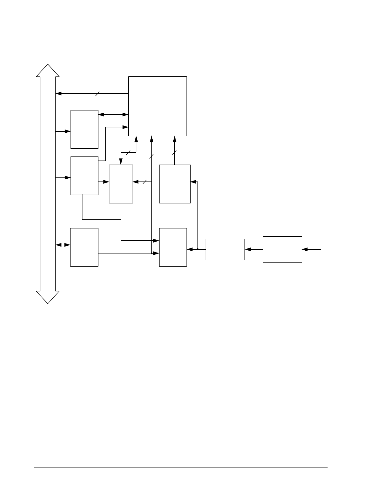
A functional block diagram of this product is shown in Figure 1 on page 12.
Interrupts are generated on any COS (positive or negative transition). Polarity is
determined by reading the input port after the COS interrupt.
NOTE: State changes that occur during the interrupt processing window (internal
request to interrupt acknowledge cycle complete) will not be detected. The time
between user input state changes must not be less than the computer interrupt
processing time; otherwise, the state changes will be lost.
A Change-of-State Application Guide that describes the complete COSMODULE™
product line, VMIC's Document No. 825-000000-002, is available from VMIC. A
summary of the COSMODULE™ product line is provided in Table 1, “Cosmodule™
Product Line Summary,” on page 13 for a list of reference.
Artisan Technology Group - Quality Instrumentation ... Guaranteed | (888) 88-SOURCE | www.artisantg.com
VMIVME-1160A 32-bit Optically Coupled Digital Input Board with Change-of-State Detection
12
Figure 1 Typical COSMODULE™Functional Block Diagram
V
M
E
b
u
s
BIM
FOUNDATION
CONTROL
LOGIC
ADDRESS
LOGIC
DATA
TRANS-
CEIVERS
IER*
LOGIC COS
DETECTION
DATA
READ
BUFFERS
INPUT**
SIGNAL
CONDITIONING
4
4
8
4
USER
INPUT
Interrupt Enable Register
Option-Dependent
*
**
7
INTERRUPT REQ LINES
DEBOUNCE
HARDWARE
Artisan Technology Group - Quality Instrumentation ... Guaranteed | (888) 88-SOURCE | www.artisantg.com

Overview
13
Functional Description
The VMIVME-1160A provides 32 high-voltage, optically coupled digital inputs with
change-of-state detection and vectoring to the byte level. The interrupt functions are
supported by the BIM. The major features of the VMIVME-1160A are:
•Quad 8-bit ports
•Change-of-State port identified with interrupt vector
•Voltage sourcing or contact sensing signal conditioning
•Double-height Eurocard form factor with front panel
•8- or 16-bit data transfers
•64-pin DIN type input connector
•Jumper-selectable nonprivileged short I/O, supervisory short I/O, or both
•32 optically coupled inputs
Table 1 COSMODULE™Product Line Summary
Item No. Description Model No. Transfer Type
1. 16-Channel AC or DC High Voltage (5 V to 240 V) Optically
Coupled Input with Change-of-State Interrupt VMIVME-1001 D8,D16
2. 32-bit TTL Digital Input with Change-of-State Interrupt VMIVME-1101 D8,D16
3. 32-bit High Voltage (5 to 50 V) Digital Input with
Change-of-State Interrupt VMIVME-1180 D8,D16
4. 32-bit High Voltage (1 to 66 V) COS board with Data
Capture Registers and Built-in-Test VMIVME-1181 D8,D16,D32
5. 32-bit Optically Coupled Digital Input with
Change-of-State Interrupt VMIVME-1160A D8,D16
Artisan Technology Group - Quality Instrumentation ... Guaranteed | (888) 88-SOURCE | www.artisantg.com

VMIVME-1160A 32-bit Optically Coupled Digital Input Board with Change-of-State Detection
14
Reference Material List
The reader should refer to "The VMEbus Specification" for a detailed explanation of
the VMEbus. "The VMEbus Specification" is available from the following source:
VITA
VMEbus International Trade Association
7825 East Gelding Dr. Suite 104
Scottsdale, AZ 85260
(602) 951-8866
FAX: (602) 951-0720
Internet: www.vita.com
The Epic Ei68C153 Bus Interrupter Module (VME) specification is available from:
Epic Semiconductor, Inc.
4801 S. Lakeshore Dr.
Suite 203
Tempe, AZ 85282
(480) 730-1000
FAX: (480) 838-4740
Internet: www.epicsemi.com
PDF for the Ei68C153: www.epicsemi.com/153.pdf
Application and Configuration Guides
The following Application and Configuration Guides are available from VMIC to
assist the user in the selection, specification and implementation of systems based on
VMIC’s products:
Physical Description and Specifications
Refer to VMIC Specification No. 800-101160-000 for a detailed explanation and
physical description of the VMIVME-1160A 32-bit Optically Coupled Digital Input
Board, available from the following:
VMIC
12090 South Memorial Pkwy.
Huntsville, AL 35803-3308, USA
(256) 880-0444
(800) 322-3616
FAX: (256) 882-0859
www.vmic.com
Title Document No.
Digital Input Board Application Guide 825-000000-000
Change-of-State Application Guide 825-000000-002
Digital I/O (with Built-in-Test) Product Line Description 825-000000-003
Connector and I/O Cable Application Guide 825-000000-006
Artisan Technology Group - Quality Instrumentation ... Guaranteed | (888) 88-SOURCE | www.artisantg.com

Overview
15
Motorola MC68153 BIM
The VMIVME-1160A was originally manufactured using the Motorola MC68153 BIM,
which is now out of production. The Epic Ei68C153 BIM is being used as a
replacement on all newly-manufactured VMIVME-1160A boards. Any references to
the Ei68C153 in this document are also applicable to the MC68153.
Artisan Technology Group - Quality Instrumentation ... Guaranteed | (888) 88-SOURCE | www.artisantg.com

VMIVME-1160A 32-bit Optically Coupled Digital Input Board with Change-of-State Detection
16
Artisan Technology Group - Quality Instrumentation ... Guaranteed | (888) 88-SOURCE | www.artisantg.com

17
CHAPTER
Theory of Operation
Contents
Priority Interrupt Subsystem . . . . . . . . . . . . . . . . . . . . . . . . . . . . . . . . . . . . . . . . . . . . . .27
Introduction
Block Diagrams
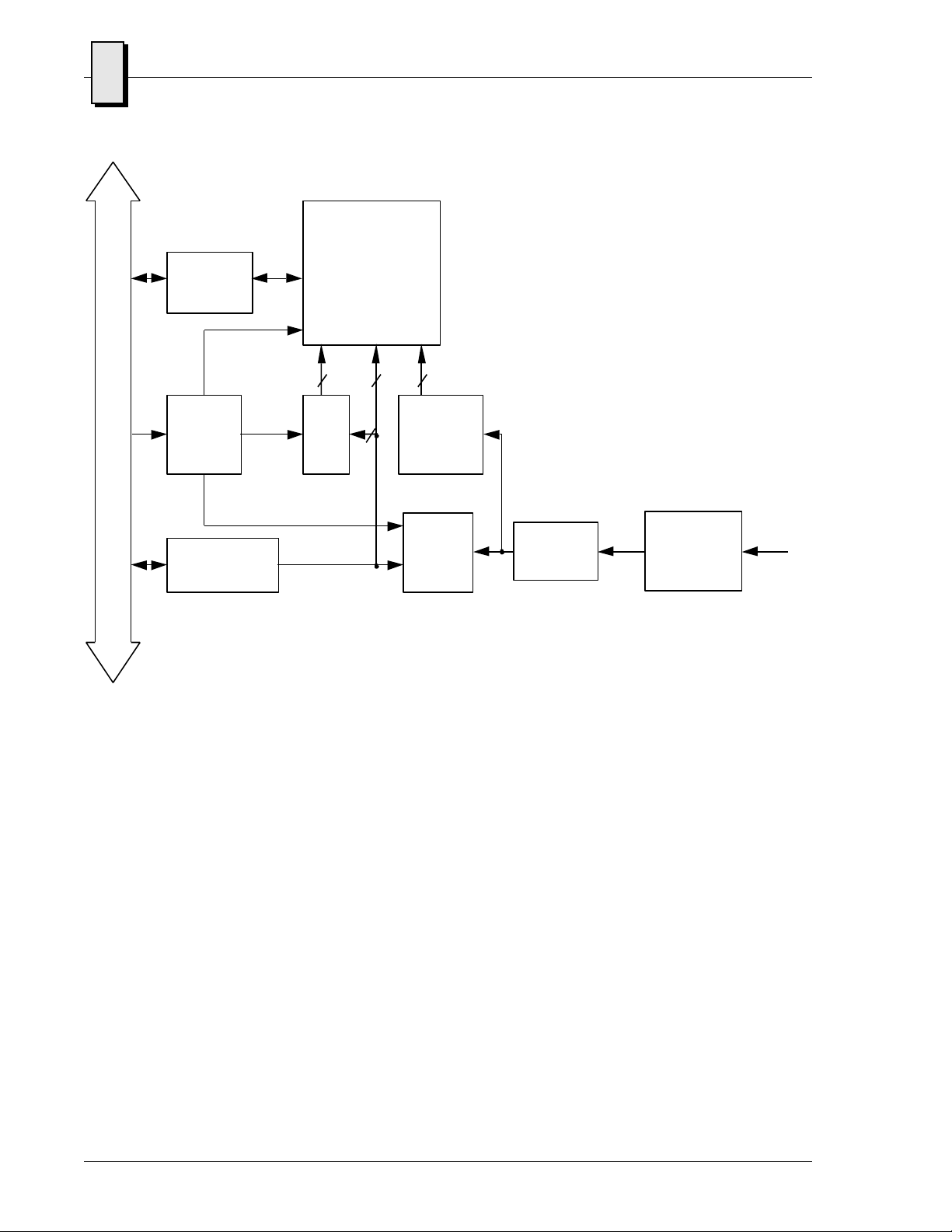
The VMIVME-1160A consists of eight functional building blocks as illustrated in
Figure 1-1 on page 18. The eight sections of the VMIVME-1160A are:
1. Address Logic
2. Control Logic
3. Data Logic
4. Bus Interrupter Module (BIM) Logic
5. Interrupt Enable Logic
6. Change-of-State Detection Logic
7. Input Data Registers
8. Input Buffers
Each section of the design is illustrated in further detail in Figure 1-2 through
Figure 1-10 starting on page 19.
Interrupt Functions
Interrupts are generated on any Change-of-State (positive or negative transition). The
polarity is determined by reading the input port after a Change-of-State interrupt
occurs. The data transfer bus, the arbitration bus, and the interrupt bus are all used in
the process of generating and handling bus interrupts.
NOTE: State changes that occur during the interrupt processing window (internal
request to interrupt acknowledge cycle complete) will not be detected. The time
between user input state changes must not be less than the computer interrupt
processing time; otherwise, the state changes will be lost.
The reader should refer to "The VMEbus Specification" for a detailed explanation of
the priority interrupt bus. See “Reference Material List”on page 14.
1
Artisan Technology Group - Quality Instrumentation ... Guaranteed | (888) 88-SOURCE | www.artisantg.com
18
1VMIVME-1160A 32-bit Optically Coupled Digital Input Board with Change-of-State Detection
Figure 1-1 VMIVME-1160A Functional Block Diagram
V
M
E
b
u
s
DATA
READ
BUFFERS
DATA
TRANSCEIVERS
*
**Internal Enable Register
Board Dependent
INPUT
SIGNAL
CONDITIONING**
INTERRUPT
CONTROL
LOGIC
BIM
FOUNDATION
ADDRESS
LOGIC
IER*
LOGIC COS
DETECTION
4
4
8 4
USER
INPUTS
INTERRUPT REQUEST LINES
DEBOUNCE
HARDWARE
Artisan Technology Group - Quality Instrumentation ... Guaranteed | (888) 88-SOURCE | www.artisantg.com

19
1
Figure 1-2 Address Section Block Diagram
C
O
M
P
A
R
A
T
O
R
=
C
O
M
P
A
R
A
T
O
R
=
C
O
M
P
A
R
A
T
O
R
=
AS*
P1
A7 to A5
A15 to A8
LWORD*
IACK*
AM0 to AM5
A
D
D
R
E
S
S
A
D
D
R
E
S
S
ADDRESS MATCH
D
E
C
O
D
E
R
WRITE IER
READ REG 1
READ REG 0
JUMPER-
SELECTABLE
FOR
SUPERVISORY
OR
NONPRIVILEGED
SHORT I/0
ACCESS
S
W
I
T
C
H
S
W
I
T
C
H
V
M
E
b
u
s
Artisan Technology Group - Quality Instrumentation ... Guaranteed | (888) 88-SOURCE | www.artisantg.com
Table of contents
Other VMIC Motherboard manuals


