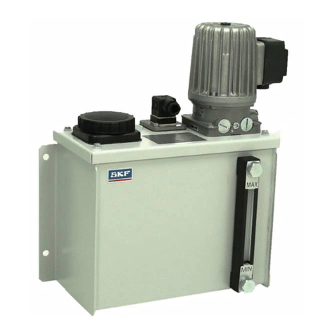
manuals.online logo
Brands
  1. Home
  2. •
  3. Brands
  4. •
  5. Vogel
  6. •
  7. Water Pump
  8. •
  9. Vogel KFA Series User manual

Vogel KFA Series User manual

ChapterNext
KFA, KFAS Pump Units
Operating Instructions
ChapterNext
Operating Instructions KFA, KFAS
This operating manual has been prepared in conformity
with the relevant standards and rules applying to
technical documentation such as VDI 4500
and EN 292.
© Copyright Willy Vogel AG
Alterations due to technical improvements reserved.
Made by:
MDC Industriewerbung & Grafik Design GmbH
Chapter
Next
Page 1
Operating Instructions KFA, KFAS
Pump Units of Series KFA
and KFASwith Control Unit
Keep for future use!
ChapterNext
Page 2
Operating Instructions KFA, KFAS
Manufacturer's Declaration in the sense of
the EC Machinery Directive 98/37/EEC
We hereby declare that the piston pumps with
reservoir of type
KFA and KFAS
are designed for incorporation into a machine / for
assembly with other machines to form a machine.
Their commissioning shall be prohibited until it is
established that the machine into which this part
has been installed or with which this part is to be
assembled conforms to the provisions of the EC
Directive 98 / 37 EC.
WILLYVOGEL
Aktiengesellschaft
Heinz Gaub Uwe Schumann
(Member of the (Sales Management lndustrial
Managing Board) Lubrication Systems)
Berlin, 26 February 2001
This declaration is made on behalf of the
manufacturer/importer
WillyVogel Aktiengesellschaft
Motzener Straße 35/37, 12277 Berlin
Postfach 480149, 12251 Berlin
by the members of the managing board
Heinz Gaub Manfred Neubert
Berlin, 26 February 2001
It is hereby confirmed for the product designated
hereinafter:
Piston pump with reservoir
type KFA10
that it conforms to the essential safety requirements
specified in the directive(s) of the Council for
harmonizing the legal regulations of the Member
States ...
Electromagnetic Compatibility
89/336/EEC,
amended by 92/31/EEC, 93/68/EEC
91/263/EEC and 93/97/EEC
Conformity has been established through the
application of the following (harmonized) European
standards:
EN 50081-1
EN 50082-2
Electrical equipment designed for use
within certain voltage limits
(LowVoltage Directive) 73/23/EEC
amended by 93/68/EEC
EN 60335-1.
EC Declaration of ConformityManufacturer's Declaration
Next
Page 3 Chapter
Operating Instructions KFA, KFAS
•This declaration certifies compliance with the
specified directives, it may not be construed as
a warranty of any qualities, however.
•The safety hints contained in the documentation
supplied along with the item shall be observed.
•The products covered by the declaration may
not be commissioned unless it has been ensured
that the machine, the vehicle or the like into
which the product has been installed conforms
to the provisions and requirements of the
applicable directives.
•Any use of the products with a mains voltage
other than that required by the applicable stan-
dards as well as non-observance of installation
hints may affect the EMC characteristics and
electrical safety.
EC Declaration of Conformity
This declaration is made on behalf of the
manufacturer/importer
Willy Vogel Aktiengesellschaft
Motzener Straße 35/37, 12277 Berlin
Postfach 480149, 12251 Berlin
by the members of the managing board
Heinz Gaub Manfred Neubert
Berlin, 26 February 2001
It is hereby confirmed for the product designated
hereinafter:
Piston pump with reservoir
type KFA1, KFAS1
that it conforms to the essential safety requirements
specified in the directive(s) of the Council for
harmonizing the legal regulations of the Member
States ...
Electromagnetic Compatibility
89/336/EEC,
amended by 92/31/EEC, 93/68/EEC
91/263/EEC and 93/97/EEC
Conformity has been established through the
application of the following (harmonized) European
standards with respect to the directives:
EN 50081-1
EN 50082-2
Motor vehicles 72/245/EEC
amended by 89/491/EEC,
95/54/EC.
ChapterNext
Page 4
Operating Instructions KFA, KFAS
6. Display mode 27
7. Programming 29
7.1 Starting the programming mode 29
7.2 Changing the lubrication interval times 29
7.3 Changing the system monitoring 30
7.4 Changing the operating mode 30
7.5 Changing the code 31
7.6 Programming ranges 31
7.7 Display ranges 31
8. Operating modes 32
8.1 Timer mode 32
8.2 Counter mode 32
8.3 No system monitoring 32
8.4 With system monitoring 32
8.5 Level monitoring 32
8.6 Monitoring via cycle switch 33
9. Technical data 34
10. Faults 35
10.1 Displaying faults 35
10.2 Clearing the fault message 35
10.3 Storing the fault times 36
10.4 Maintenance and repair 36
10.5 Block operation 37
10.6 Pump faults 38
Service Germany 40
Service world-wide 41
1. Safety hints 6
2. Installation 8
2.1 Installation dimensions 9
2.2 Pump unit versions 9
2.3 Pump elements 10
2.4 Replacing pump elements 11
2.5 Pressure relief valves 12
2.6 Lubricant filling 12
Initial filling 13
2.7 Level monitoring 13
2.8 Bleeding the system 13
3. Electrical connection – vehicles 14
3.1 General electrical specifications 14
3.2 KFA1, KFA1-W 15
3.3 KFAS1, KFAS1-W 16
4. Electrical connection –
industrial applications 17
4.1 General electrical specifications 17
4.2 KFA1-M, KFA1-M-W 18
4.3 KFAS1-M, KFAS1-M-W 19
4.4 KFAS1-M-Z, KFAS1-M-W-Z 19
External cycle switch 20
4.5 Color coding table 20
4.6 KFA10, KFA10-W 21
5. Display and control unit 22
5.1 3-digit LED display 23
5.2 Display via light-emitting diodes 25
5.3 Operation via pushbuttons 26
Contents
ChapterContents
Page 5
Operating Instructions KFA, KFAS
Filling
Page 12
Electrical connection Industrial
applications Page 17
Pump elements
Page 10
Installation
Page 8
Control general
Page 22 Electrical connectionVehicles
Page 14
Pressure
relief valve
Page 12
KFA KFAS with control unit
ChapterNext
1
Page 6
Operating Instructions KFA, KFAS
General
The components are designed and manufactured
in conformity with the generally accepted
engineering standards as well as applicable
industrial safety and accident prevention
regulations. Though constructed to meet all relevant
safety requirements, their use may still entail
dangers leading to personal injury of the user or
third parties or damage to property. Therefore, the
components shall only be used when they are in
a technically perfect condition, the operating
instructions having to be duly observed.Any faults,
in particular faults which may affect safety, shall
be rectified without delay.
Use in conformity with intended purpose
The Vogel pump units type KFA and KFAS are
designed for the supply of centralized lubrication
systems of vehicles, plants and machines. They
are capable of delivering greases up to NLGI
grade 2.
Any use beyond this scope shall be deemed as
being not in conformity with the intended purpose.
Approved personnel
The components described in this manual may be
installed, operated, maintained and repaired only
by qualified personnel.
Qualified personnel means persons trained,
assigned and instructed by the operator of the
Installation work
Wen installing the products in vehicles and
machines, the local accident prevention regulations
as well as the applicable operating and
maintenance instructions shall always be observed.
Danger caused by electrical current
The units may be connected to the power supply
exclusively by appropriately trained qualified
personnel in conformity with the local connection
conditions and regulations (e.g. DIN, VDE)!
Improperly connected equipment may lead to
serious personal injury and damage to property!
Danger caused by system pressure
The units may be pressurized. Therefore, they
must be made pressure-less before any extension
work, modifications or repairs are carried out.
1. Safety hints
units. These persons are familiar with the applicable
standards, rules, accident prevention regulations
and operating conditions on account of their training,
experience and the instructions received. They are
entitled to carry out the activities required in a
given case and will be able to recognize and avoid
possibly existing dangers.
DIN VDE 0105 or IEC 364 contains the definitions
for specialists and the prohibition to use unqualified
personnel.
Disclaimer of liability
Vogel cannot be held liable for any damage:
•caused by lack of lubricant
•caused by contaminated or unsuited lubricants
•caused by the installation of components or
spare parts other than genuine Vogel
components or spare parts, respectively
•caused by any use which is not in conformity
with the intended purpose
•caused by inappropriate installation and filling
•caused by wrong electrical connection
•caused by erroneous programming
•caused by improper reactions to malfunctioning
•caused by non-observance of the operating
instructions
Page 7 ChapterContents
1
Operating Instructions KFA, KFAS
Transport and storage
The pump units KFA and KFAS are packed in
conformity with standard packaging practice such
that the regulations in the country of destination
as well as DIN ISO 9001 are met.
There are no limitations with respect to land, air
or sea transport. Store in a dry place at a storage
temperature of -40 °C to +70 °C.
Handle with care!
This symbol appears in the manual
whenever it is necessary to draw your
attention to special dangers or important
actions.
Permitted lubricants
Greases up to NLGI grade 2 DIN 51818 and a
flow pressure of 700 mbars maximum.
The release list of permitted lubricants is updated
on an ongoing basis and is available from the
following address:
„Schmierstoffe für Progressivanlagen“
(Lubricants for Progressive Systems) at:
www.vogelag.com
Also refer to the release lists of the
machine or vehicle manufacturers!
Hazard to the environment posed by lubricants
The lubricants recommended by the manufacturer
have been formulated to meet the relevant safety
regulations. Oils and greases nevertheless
principally continue to be substances hazardous
to ground water, and special precautions shall be
taken for their storage, processing and
transportation.
ChapterContents
2
Page 8
Operating Instructions KFA, KFAS
2. Installation
Mount the KFAand KFAS pump units to the vehicle
or machine with the 3 supplied M8 bolts, washers
and self-locking nuts.
Tightening torque: 16 Nm.
The unit should be mounted at a position which is
protected to the greatest possible extent. Where
holes have to be drilled for installation, position
these holes as shown below. Adrilling template is
available under order number 951-130-148.
General
The pump units of the KFA and KFAS series are
designed for use in centralized lubrication systems
of vehicles, machines and plants. They are capable
of delivering greases up to NLGI grade 2.
The pump units differ in the way they can be
electrically connected as well as in the control and
monitoring of functions. If application specific pump
elements are installed, up to two separate
lubrication circuits can be operated with one unit
(see section 2.3).
Units of the KFA and KFAS series may
be operated exclusively in systems
provided with a pressure relief valve!
If this requirement is not observed,
overpressure may cause serious personal injury
and damage to property.
When drilling, pay attention to the
following possible hazards:
•Existing supply lines
•Other units
•Moving parts
•Heat sources (exhaust etc.)
Mind safety distances as well as local
installation and accident prevention regulations.
Figure 1 Mounting holes
Bolts, washers and self-locking nuts for fastening
the unit are part of the scope of supply. 3 M8 each,
tightening torque 16 Nm
150 ±0,4
100 ±0,4
ChapterContents
2
Page 9
Operating Instructions KFA, KFAS
150
2.1 Installation dimensions
KFA1
KFA1-M
KFA10
KFA1-W
KFA1-M-W
KFA10-W
KFAS1
KFAS1-M
KFAS1-M-Z
KFAS1
KAFS1-W
KFAS1-M-W
KFAS1-W
KFAS1-M-W-Z
Type
Vehicle 12 V or 24 V DC
Industry 24 V DC
Industry 115 V or 230 VAC
Vehicle 12 V or 24 V DC
Industry 24 V DC
Industry 115 V or 230 VAC
Vehicle 12 V or 24 V DC
Industry 24 V DC
Industry 24 V DC
Vehicle 12 V or 24 V DC
Industry 24 V DC
Vehicle 12 V or 24 V DC
Industry 24 V DC
Application Function Control
Without level monitoring
External
With level monitoring
Without level monitoring
With cycle switch monitoring
With level monitoring
With cycle switch monitoring
Internal
Figure 2 Installation dimensions
216
234
Weight with filled lubricant reservoir:
KFAS1 3.7 kg, KFA10 4.8 kg
2.2 Pump unit versions
ChapterContents
2
Page 10
Operating Instructions KFA, KFAS
2.3 Pump elements
The pump units KFA and KFAS are fitted with two
lubricant outlet ports. To each outlet port, a separate
pump element for an independent progressive
feeder circuit can be connected.
Order the pump elements in accordance with your
specific lubrication application.
The pump element is fitted only with
O-ring 15.4x2.1 (1) without any additional
seal ring.
Figure 3 Pump element
Close any outlet ports which are not required with
a screw plug according to DIN 910-M18x1.5-5.8
with seal ring according to DIN 7603-A18x24-Al.
1
All pump elements are provided with an internal
thread M14x1.5 for connection to a pressure
relief valve with tube port for steel tubes 6 mm
or 10 mm.
The pump elements are externally marked on the
spanner surface with grooves.
Available pump elements
The quoted values refer to a temperature
of 20 °C and a back pressure of 50 bars.
4
2
3
1
Figure 4Connection of pump elements and
pressure relief valve
1Conical head lubrication nipple
2Screw plug
3Pump element
4Pressure relief valve
KFA1.U1 2.0 1
KFA1.U2 1.5 2
KFA1.U3 1.0 3
Order No. Output
in cm3/min Number
of grooves
ChapterContents
2
Page 11
Operating Instructions KFA, KFAS
2.4 Replacing pump elements
Mount and dismount pump elements
only when unit is disconnected from
power supply. Failure to comply with this
requirement may lead to bodily injury or damage
to the unit.
Too little or no lubricant at all will be delivered if a
pump element is worn.After dismounting the main
line and pressure relief valve, you can keep the
outlet port of the pump element closed with a finger
when the pump operates to deliver lubricant. This
is a sign that the element is worn.
Step 1:
Screw out pump element.
If the piston of the pump element gets stuck in the
lubricant present in the strainer ring, remove it with
a suitable tool.
Step 2:
Remove bothersome lubricant between the fixing
thread, guiding slot in the strainer ring and the
groove between the cam-disc and return disc with
a suitable tool.
Figure 6 Sectional top view of pump casing
1Fixing thread
2Guiding groove in strainer ring
3Cam-disc
4Return disc
Step 3:
Pull piston of the new pump element as far as
possible out of the element, and insert it along the
guiding slot of the strainer ring in the groove
between the cam-disc and return disc.
If the pump element has not been correctly fitted,
it is not possible to tighten the thread!
Figure 7Inserting the pump element
Figure 5 Removing the piston
3421
ChapterContents
2
Page 12
Operating Instructions KFA, KFAS
The pressure relief valve is used to protect the
entire lubrication system against excessive internal
pressures. The valve is set to open at a pressure
of 300 bars. If the operating pressure increases
beyond 300 bars due to a blocked progressive
feeder or lubricating point, the valve opens, and
grease visibly emerges from the valve.
This allows optical system monitoring.
AConnection for tube 10 mm
Figure 6Pressure relief valves
AConnection for tube 6 mm
PConnecting thread for pump element
RGrease emerges here in case of
2.5 Pressure relief valves
R
A
M14x1.5
P
R
M14x1,5
PA
The lubricant is filled in via the conical head
lubrication nipple DIN 71412-AM10x1 with a
standard pressure grease gun.
Order No. Tube Opening pressure
in bars
161-210-012 ø6 mm 300 ±20 bars
161-210-016 ø10 mm
2.6 Lubricant filling
Figure 8 Side view
1Conical head lubrication nipple
2 Pressure relief valve
3Follower
4„max“marking
5Lubricant
6„min“marking
4
3
5
6
2
1
ChapterContents
2
Page 13
Operating Instructions KFA, KFAS
Initial filling
Which lubricants may be used with the units may
be seen from the current release list "Schmierstoffe
für Progressivanlagen"
at: www.vogelag.com
When the unit is filled for the first time, the lubricant
forces the follower upward until the overfill outlet
opens. As filling continues, the air escapes until
the entire reservoir is filled with lubricant. When
excess lubricant starts to emerge from the overfill
outlet, stop filling completely.
When topping up, take care not to let lubricant
emerge from the overfill outlet. Danger of accident
or environmental pollution!
Figure 9 Point at which lubricant emerges
Visual
The transparent reservoir enables you to visually
monitor the level. The level should be checked at
regular intervals for safety reasons. The current
level can be precisely seen from the position of
the follower.
When the level in the reservoir has
dropped below the „min“marking, bleed
the entire system.
Level switch
Pump units of the KFA and KFAS series are
available with an automatic level control function
(see section 2.2).
KFAS: When the level drops below the „min“
marking, the sequence of operations is
stopped, and a fault message „FLL“
appears in the display.
KFA: The level signal is output via the
appropriate connector
(see sections 3.2, 4.2, 4.6).
Note!
Pump units with electrical level control are identified
by a „W“in the order description.
2.7 Level monitoring
•Disconnect the main lines from the unit. Operate
the pump until the lubricant emerging from the
pressure relief valve is free of bubbles.
Reconnect the main lines.
•Disconnect the main line from the main
distributor. Operate the pump until the emerging
lubricant is free of bubbles. Reconnect the
main line.
•Disconnect secondary lines from main distributor.
Operate the pump until bubble-free lubricant
emerges from all ports of the main distributor.
Reconnect the secondary lines.
•Finally, bleed secondary lines, secondary
distributors, lubricant lines and lubrication points,
and check for proper functioning.
2.8 Bleeding the system
ChapterContents
3
Page 14
Operating Instructions KFA, KFAS
3. Electrical connection - vehicles
Mind voltage values specified on
nameplate! 3.1 General electrical specifications
KFA1... / KFAS1... 24 V DC 0.5 A ca. 1.4 A 3.0 A
Vehicles 12 V DC 1.0 A ca. 2.8 A 3.0 A
Duty type S3 20%,
50 min
2) Typical value at an ambient temperature = 25 °C and operating pressure = 300 bars
3) Fuse according to DIN 72581 T.3
Rated voltage Typical power
input (load-
dependent)2)
Starting current
(ca. 20 ms) Back-up fuse3)
ChapterContents
3
Page 15
Operating Instructions KFA, KFAS
Mind voltage values given on nameplate
and in section 3.1 !
The pump units are connected to the power supply
via a 4-pole circular pin-and-socket connector
according to DIN 72585-A1-4.1-Ag/K1.
Figure 10 Circular pin-and-socket connector
3.2 KFA1, KFA1-W KFA1 without level monitoring
Cable set
KFA1-W with level monitoring
Cable set
1) External control unit
Relay contact „Pump ON“
5) PIN without internal connection
Fuse F according to DIN 72581 T3
Core colors, see section 4.5
15 31
WS Contact position of built-in level switch is for
„Filled reservoir“, i.e., the level switch opens
when the lubricant quantity is insufficient
4) Evaluation of level switch signal
997-000-820 10 m 12 m
Order
number Length of
corrugated tube Length of
cores
997-000-706 10 m 12 m
Order
number Length of
corrugated tube Length of
cores
1
BN
KFA1
F
234
5)
X1
RD-BK
3A
1)
5)
+
M
-
-
1
BN
KFA1-W
F
234X1
RD-BK
15
3 A
1)
+
M
-
31
-WS
BK
PK
Q
max.
0,5 A
4)
2
4
3
1
X1
ChapterContents
3
Page 16
Operating Instructions KFA, KFAS
Cable sets
3.3 KFAS1, KFAS1-W
15 + potential supply voltage
(ignition switch ON)
31 - potential supply voltage (0 V, GND)
DK external pushbutton „Intermediate lubrication“
ZS external cycle switch
SL1 signal lamp „Pump is operating“
SL2 signal lamp „Fault“
Fuse F according to DIN 72581 T3
Core colors, see section 4.5
Mind voltage values given on nameplate
and in section 3.1 !
The unit is connected via the 7-pole circular
connector.
Figure 11 Circular pin-and-socket connector
KFAS1/KFAS1-W
without cycle switch monitoring
PINS 5 and 6 have no function. Do not jumper!
In the programming mode, the following
monitoring function must be activated
COP = OFF (factory setting).
With cycle switch monitoring
Connect the external cycle switch to PINS
5 and 6. In the programming mode, the following
monitoring function must be activated
COP = CS (see section 7.3).
KFAS1
No internal level monitoring
KFAS1-W
With internal level monitoring
Abuilt-in level monitoring facility is always active.
When the level drops below the "min" mark, the
sequence of operations is stopped, and a fault
message appears in the display.
The electrical connection details are identical
with those of the KFAS1 unit.
1
KFAS1
X1
BN
KFAS1-W
234567
RD-BK
F
15
3A
31
2,4 W
DK SL2 ZS +
BU
BK
BK
VT-GN
PK
Order
number Length of
corrugated tube
2
4
5
3
1
67
X1
997-000-630 12 m 12.2 m
997-000-650 16 m 16.2 m
SL1
2,4 W
Length of
cores
ChapterContents
4
Page 17
Operating Instructions KFA, KFAS
4. Electrical connection–industrial applications
Mind voltage values specified on
nameplate!
Observe the information and instructions
contained in the operating manual and func-
tional description of the respective control unit
as well as the safety hints (see section 1)!
If the protective conductor connection is not
established or interrupted, dangerous touch
voltages may occur on the unit!
4.1 General electrical specifications
KFA1-M... / KFAS1-M... 24 V DC1) 0.5 A ca. 1.4 A 3.0 A
Industrial applications
Duty type S3 20%,
50 min
KFA10 / KFAS10-W 230 V/50 Hz 0.45 A - 4.0 A
Industrial applications 230 V/60 Hz 0.66 A - 4.0 A
Duty type S3 10%, 115 V/50 Hz 1.0 A - 4.0 A
50 min 115 V/60 Hz 1.3 A - 4.0 A
1) Protective measures to be applied to ensure operation in accordance with specifications:
„Funktionskleinspannung mit sicherer Trennung“/ „Protective Extra Low Voltage“(PELV)
Standards: EN 60204 Part 1:1992 / EIC 204-1:1992, modified
DIN VDE 0100 Part 410 / IEC 364-4-41:1992
2) Typical value at an ambient temperature = 25 °C and operating pressure = 300 bars
4) Lead: Cross-section 1.5 mm2,length ≤12 m
External control units for KFA1 units
The following external control units are used for the control of the lubrication and pause times as well
as for monitoring the lubrication process: IGZ 51-20-E, IGZ 51-20-S2-E, IGZ 51-20-S7-E,
IGZ 51-20-S8-E.
Rated
voltage Typical power
input (load-
dependent)2)
Pump starting
current
(ca. 20 ms)
Max.
back-up fuse4)
ChapterContents
4
Page 18
Operating Instructions KFA, KFAS
Supply voltage 24 V DC
Mind voltage values specified on
nameplate and in section 4.1!
X1 Electrical connection: Pin-and-socket
connector according to DIN 43650-A.
X2 Signal output from level switch WS
circular pin-and-socket connector M12x1.
4.2 KFA1-M, KFA1-M-W
Figure 12 Pin-and-socket connectors KFA1-M-W
Connector
3
1
2
4 3
12
X1
X2
KFA1-M without level monitoring
This unit is provided only with pin-and-socket
connector X1.
1) External control unit
relay contact „Pump ON“
5) PIN without internal connection
WS Built-in level switch. Contact position shown:
Filled reservoir, i.e. contact 1 - 4 opens in
case of insufficient lubricant quantity
L+ + potential supply voltage
(main switch of machine ON)
M -potential supply voltage
KFA1-M-W with level monitoring
This unit is provided with the pin-and-socket
connectors X1 and X2.
Color coding
X2-PIN Color code Core color
1 BN brown
2 WH white
3 BU blue
4 BK black
24 V DC
M
-
1
KFA1-M
KFA1-M-W
23X1
M (OV, GND)
1)
+
-
L+
F 3A
5) 5)
3
1
2
4
X2
Connector
3
12
KFA1-M-W
231X2
BN
4
+
24 V DC, max. 0.5 A
Q
WS
MIN 5) OK
WH
BU
BK

This manual suits for next models

14

Other Vogel Water Pump manuals

Vogel MFE5-KW3-2 User manual

Vogel

Vogel MFE5-KW3-2 User manual

Vogel Prisma Series User manual

Vogel

Vogel Prisma Series User manual

Popular Water Pump manuals by other brands

EasyCare HARVEST 2 General User/ Safety Guide

EasyCare

EasyCare HARVEST 2 General User/ Safety Guide

Grundfos NB Safety instructions

Grundfos

Grundfos NB Safety instructions

EMP OP80 Installation and operation manual

EMP

EMP OP80 Installation and operation manual

Hans Premium Water 2 owner's manual

Hans

Hans Premium Water 2 owner's manual

Goulds Pumps 3198 Installation, operation and maintenance manual

Goulds Pumps

Goulds Pumps 3198 Installation, operation and maintenance manual

Sotera 400B Series Owner's operation manual

Sotera

Sotera 400B Series Owner's operation manual

Bosch rexroth A2FO Series instruction manual

Bosch

Bosch rexroth A2FO Series instruction manual

LEYBOLD TRIVAC E2 operating instructions

LEYBOLD

LEYBOLD TRIVAC E2 operating instructions

PEDROLLO TOP MULTI-TECH Operation manual

PEDROLLO

PEDROLLO TOP MULTI-TECH Operation manual

Sicce Syncra ADV Series instruction manual

Sicce

Sicce Syncra ADV Series instruction manual

Pentair Fairbanks nijhuis 1820 Installation, operation and maintenance

Pentair

Pentair Fairbanks nijhuis 1820 Installation, operation and maintenance

GORMAN-RUPP PUMPS VG6D3-B Installation, operation, and maintenance manual with parts list

GORMAN-RUPP PUMPS

GORMAN-RUPP PUMPS VG6D3-B Installation, operation, and maintenance manual with parts list

BUSCH COMBI COBRA DS 3010 G instruction manual

BUSCH

BUSCH COMBI COBRA DS 3010 G instruction manual

Grizzly GP 2832 K Translation of the original instructions for use

Grizzly

Grizzly GP 2832 K Translation of the original instructions for use

Regulus BIO 55 MIX W-PWM 1F TRS6K Installation and operation manual

Regulus

Regulus BIO 55 MIX W-PWM 1F TRS6K Installation and operation manual

Grundfos Fire DNF Installation and operating instructions
Grundfos

Grundfos Fire DNF Installation and operating instructions
Fieldmann FVC 4001-EK user manual

Fieldmann

Fieldmann FVC 4001-EK user manual

Grundfos JP PS Series Service instructions
Grundfos

Grundfos JP PS Series Service instructions

manuals.online logo
manuals.online logoBrands
  • About & Mission
  • Contact us
  • Privacy Policy
  • Terms and Conditions
Copyright 2025 Manuals.Online. All Rights Reserved.