EMP OP80 User manual

Rev
Rev By
Date
Description of Change
Approved By
C
ME
7/29/20
Revisions
ECN6044
D
ME
6/30/21
Revisions
ECN6236
9970115018 Rev. D – 06/30/2021 © 2019 EMP, Inc. 1
Installation and Operation Manual
OP80 Electric Oil Pump
This manual is effective for aftermarket and OEM
installations of the following part numbers:
Base Part Number
1010115XXX

Product Overview
The information contained in this manual is updated periodically. While great care is taken in compiling the information contained in this manual, Engineered
Machined Products, Inc. cannot assume liability for losses of any nature arising from any errors and/or omissions.
The information and specifications contained throughout this manual are up to date at the time of publication. Engineered Machined Products, Inc. reserves
the right to change the content of this manual at any time without notice.
© 2019 EMP, Inc. 2
Engineered Machined Products Inc.
2701 North 30th Street
Escanaba, MI, USA 49829
Phone: +1 (906) 789-7497
www.emp-corp.com
Service@emp-corp.com
Product Overview
Thank you for purchasing the EMP OP80 electric oil pump. Please read through this entire manual before
beginning any work on integrating and/or installing this pump. EMP cannot be held responsible for any specific
use or misuse of this product. The purpose of this manual is to assist you in installing, operating, and maintaining
your OP80 electric oil pump.
Your oil pump is an electronically controlled positive displacement gear pump. The OP80 oil pump features a
brushless DC motor with an integrated motor drive controller. This pump is available in both 12 and 24 VDC
models.
The OP80 pump is capable of delivering up to 8 gal/min (30 L/min) of oil flow. It is capable of operating at system
pressures up to 80 psi (5.5 Bar). This performance allows the pump to handle a variety of fluid transfer
applications. These applications include those with use for motor oils, hydraulic fluids, transmission fluids, and
gear lubes. Current pump models have been optimized for lighter weight oils like ATF. Performance will be
reduced for heavier weight oils.
CAUTION:Do not use this pump for transferring any fluids other than those for which it was designed;
to do so may damage the pump and will void the warranty.
To assure the longest possible service life, it is important that you follow all guidelines as outlined in this manual.
It is challenging to address every possible installation type. EMP is always happy to help in assisting with the
integration or installation of this product. If you are in doubt about anything outlined in this manual, please contact
EMP technical service for assistance at service@emp-corp.com.
OEM Engineers: OEM installations must meet all EMP installation and use guidelines to ensure warranty
coverage. For review of your proposed implementation, contact service@emp-corp.com.
!

Table of Contents
© 2019 EMP, Inc. 3
Table of Contents
Product Overview ..............................................................................................................................................2
Introduction........................................................................................................................................................4
Purpose .........................................................................................................................................................4
Service Technician Responsibilities ...............................................................................................................4
Liability Disclaimer .........................................................................................................................................4
Additional Information ....................................................................................................................................4
Technical Help ...............................................................................................................................................4
Warranty ........................................................................................................................................................4
About This Document ........................................................................................................................................5
Warnings, Cautions and Notes.......................................................................................................................5
Definition of Terms.........................................................................................................................................5
Product Safety Warnings ...................................................................................................................................6
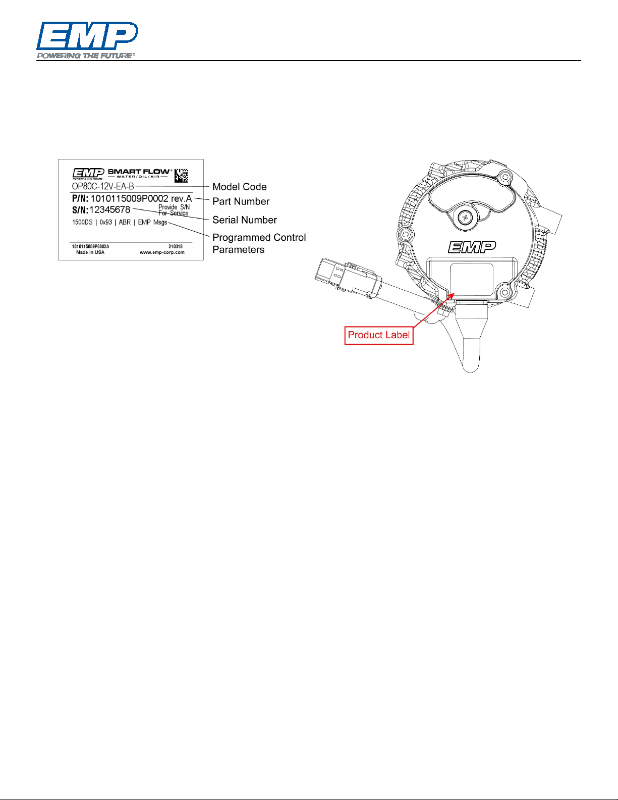
Identification ......................................................................................................................................................7
EMP Oil Pump Model Codes..........................................................................................................................8
Technical Information ........................................................................................................................................9
Operation .......................................................................................................................................................9
Specifications.................................................................................................................................................9
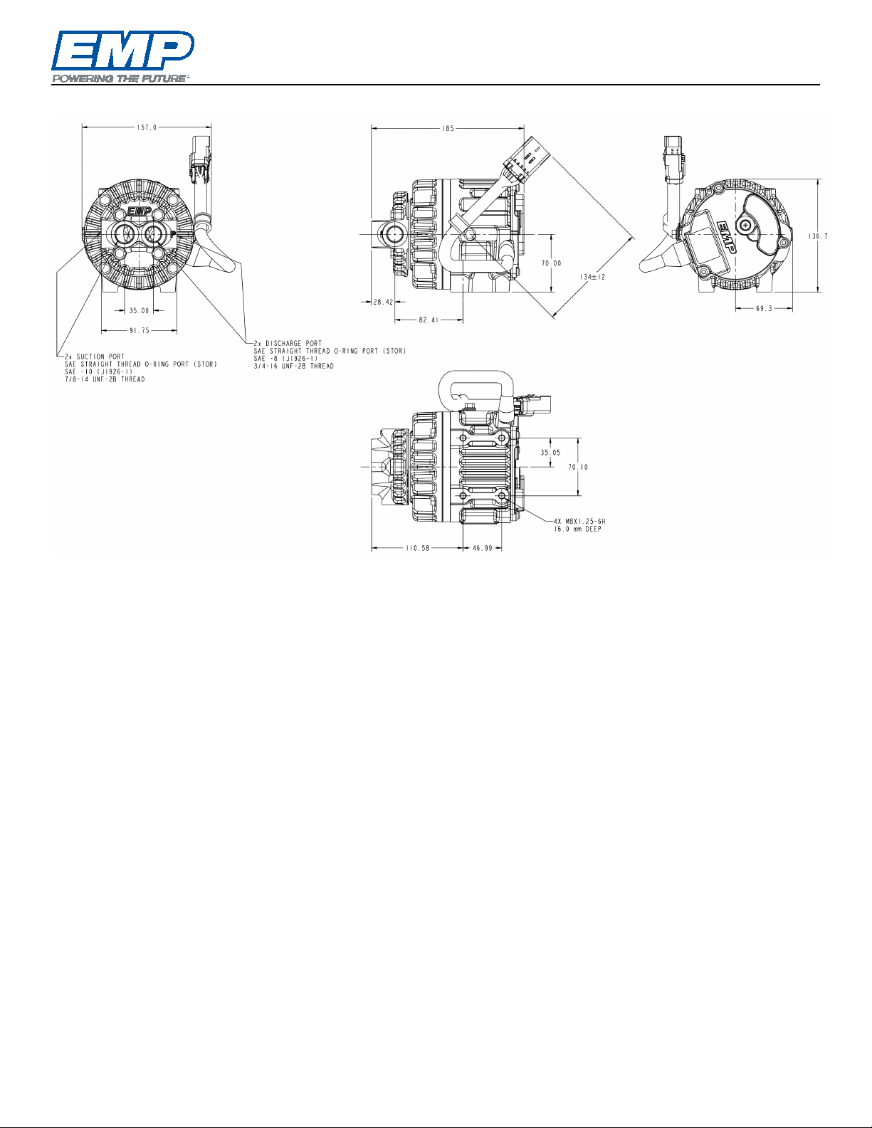
Dimensional and Mounting Details ...............................................................................................................10
Sample Performance Chart..........................................................................................................................11
Installation .......................................................................................................................................................13
Locations/Orientations ................................................................................................................................. 13
Plumbing Considerations .............................................................................................................................13
Wiring Practices ...........................................................................................................................................14
Service Parts Replacement .............................................................................................................................14
Fluids Fill .........................................................................................................................................................15
Final Item Checklist .........................................................................................................................................15
Installation Review Checklist ...........................................................................................................................15
Routine Maintenance.......................................................................................................................................16
Troubleshooting...............................................................................................................................................16
Appendix A ......................................................................................................................................................17
Operation Manual R20L Controller Board ....................................................................................................17
Appendix B ......................................................................................................................................................18
Operation Manual R20C Controller Board....................................................................................................18
Product Warranty Registration Form................................................................................................................ 19

Introduction
© 2019 EMP, Inc. 4
Introduction
Purpose
The purpose of the manual is to present information and procedures required to properly install, service, and
maintain your pump assembly.
Service Technician Responsibilities
Ensure that all safety messages and information messages are read and understood before installation,
maintenance, or repairs are performed. It is important to use caution when service work is performed. Knowledge
of impacted systems and their operation are important before the removal or disassembly of any component.
Liability Disclaimer
EMP cannot anticipate every possible circumstance that might involve a potential hazard. The safety messages
in this document, in related manuals, and on the product are therefore not all inclusive. If a tool, procedure, work
method, or operating technique that is not specifically recommended by EMP is used, you must satisfy yourself
that it is safe for you and for others. You should ensure that the product will not be damaged or be made unsafe
by the operation, maintenance, or repair procedures that you choose.
Additional Information
Access https://www.emp-corp.com/support/ for service software, service bulletins, service manuals, service
drawings, and other documents related to your installed EMP systems and components. First time users may
create a free customer login at http://www.emp-corp.com/account/register/.
Technical Help
Contact EMP Customer Service for technical help at +1 (906) 789-7497 or service@emp-corp.com.
Warranty
Mail, Fax, or Email the completed warranty registration form at the end of the document to:
EMP Advanced Development, LLC
2701 North 30th Street
Escanaba, MI, USA 49829
FAX# +1 (906) 789-7825
warranty@emp-corp.com

About This Document
© 2019 EMP, Inc. 5
About This Document
Warnings, Cautions and Notes
Two headings are used in this document to stress your safety and safe operation of the system. They are styled
with a graphic bullet and bold, uppercase text: WARNING and CAUTION. Warnings highlight risks to
personnel — hazards, unsafe conditions and practices that can result in personal injury or death. Cautions
indicate conditions or practices that can cause damage to components, systems, or other equipment.
A third heading, styled as NOTE, calls attention to additional information about components and procedures
discussed in the document.
Definition of Terms
EMP-Link...... EMP Based Proprietary Serial Data Bus
Ignition Enable.........Signal that commands the controller to turn on/wake-up
OP80 ............. Oil Pump with Integral Controller and EMP- Link or PWM Communications
OP80C .......... Oil Pump with Integral Controller and J1939 CAN Communications or Thermistor Input
!
!

Product Safety Warnings
© 2019 EMP, Inc. 6
Product Safety Warnings
WARNING: EMP cannot anticipate every possible circumstance that might involve a potential hazard.
The safety messages in this document, in related manuals, and on the product are therefore not all inclusive.
If a tool, procedure, work method, or operating technique that is not specifically recommended by EMP is
used, you must satisfy yourself that it is safe for you and for others. You should ensure that the product will
not be damaged or be made unsafe by the operation, maintenance, or repair procedures that you choose.
WARNING: Ensure that all safety messages and information messages are read and understood before
installation, maintenance, or repairs are performed. It is important to use caution when service work is
performed. Knowledge of impacted systems and their operation are important before the removal or
disassembly of any component.
WARNING: Make sure the equipment cannot move before doing any work or diagnostic procedures on
the EMP component, system, or vehicle.
WARNING: When working near electric components, ensure they cannot activate unexpectedly.
Remove power or utilize lock out switches.
WARNING: Use extreme caution when working on systems under pressure (i.e. coolant, hydraulic
fluids, air, fire suppression, etc.).
WARNING: Make sure the work area is ventilated and well lit.
WARNING: Make sure charged fire extinguishers are in the work area.
WARNING: Reinstall all safety guards, shields and covers.
WARNING: Make sure all tools, parts and service equipment are removed from the work area.
WARNING: Ensure that all system power and ground connection points are torqued to EMP and/or
OEM specifications to prevent system damage. Failure to follow specified torque requirements can result in
loose connections which can damage electronic components and will void EMP warranty.
!
!
!
!
!
!
!
!
!
!

Identification
© 2019 EMP, Inc. 7
Identification
Each component is labeled with a model code, part number and serial number. The model code reflects hardware
configuration options of the component (see the next page). The part number is based on the combined hardware
and software configuration of the component. Each serial number is unique. Provide the component serial
number with all enquiries to EMP technical service, it is used trace the component hardware configuration,
software calibration, date of manufacture, and other manufacturing data.
Example Product Label

Identification
© 2019 EMP, Inc. 8
EMP Oil Pump Model Codes
Example: OP80-24V-EA-L
OP
80
-
24V
-
E
A
-
L
[OEM]
[Cert]
[Suffix]
1
2
3
4
5
6
7
8
9
10
11
12
1
Component
OP = Oil Pump
5
Voltage
12V = 12 volt
24V = 24 volt
9
I/O
Omit if n/a
A = Address Input
C = Temperature Input
B = Address or Temp Input
(Specified in Calibration)
M = PWM High (modulated)
L = PWM Low (modulated)
–––––––––––––––––––––––
–––––––––––––––––––––––
–––––––––––––––––––––––
2
Scavenge Flow Rate
In 0.1 gallons per minute
35 = 3.5 gpm (13.2 lpm)
Omit for single stage pumps
6
Mounting
E = External Mount
C = Cartridge Mount 10
OEM
Omit if n/a
–––––––––––––––––––––––
–––––––––––––––––––––––
–––––––––––––––––––––––
3
Pressure Flow Rate
In 0.1 gallons per minute
30 = 3.0 gpm (11.4 lpm)
40 = 4.0 gpm (15.1 lpm)
80 = 8.0 gpm (30.3 lpm)
7
Orientation (degrees)
A = 0
B = 90
C = 180
D = 270
11
Certification
Omit if n/a
–––––––––––––––––––––––
–––––––––––––––––––––––
–––––––––––––––––––––––
4
Communication
C = CAN
Omit for on/off or PWM
8
Relief Valve Cracking
Pressure
Omit if n/a
12
Suffix
Omit if n/a
Denotes model variation
–––––––––––––––––––––––
–––––––––––––––––––––––
–––––––––––––––––––––––
OP80-24V-EA-L = Oil Pump. Single stage, 8.0 gpm pressure, on/off/PWM communication, 24 Volt External
Mount at 0 degrees, no relief valve, uses PWM Low input for commands.
NOTE: Not every option combination is available.
NOTE: All current pump models are optimized for use with lighter weight oils like ATF. Performance will be
reduced for heavier weight oils.

Technical Information
© 2019 EMP, Inc. 9
Technical Information
Operation
Connector, operation, and wiring information are in the appendices, depending on the pump model.
Model OP80 pumps are explained in Appendix A, Operation Manual R20L Controller Board.
Model OP80C pumps are explained in Appendix B, Operation Manual R20C Controller Board.
Specifications
*NOTE: Reference the pump performance charts for the typical performance capability of the oil pump
using a light weight oil.
NOTE: Performance will be reduced at lower operating temperatures when using lower voltage power
supplies and when using heavier weight oils.
Component Construction
Cast Aluminum
Performance
Model: 12V and 24V
Theoretical Displacement 0.468 in3/rev (7.67 cm3/rev)
Flow Capacity Maximum* 8.0 gal/min (30 L/min)
Operating Pressure Maximum* 80 psi (5.5 Bar)
Operating Temperature Maximum (Air) 203 °F (95 °C)
Operating Temperature Maximum (Oil) 212 °F (100 °C)
Operating Temperature Minimum 32 °F (0 °C)*
(*Sub-zero operation is application dependent)
Oil Viscosity Maximum ~5000 cSt
(Current models optimized for lighter weight oils like ATF)
Motor Speed Maximum 5000 rpm
Motor Speed Minimum 500 rpm
Motor Speed Default
4000 rpm (configurable)
Mechanical Connections
Model: 12V and 24V
Suction SAE STOR -10 (7/8-14 UNF-2B)
Discharge SAE STOR -8 (3/4-16 UNF-2B)
Weight
Model: 12V and 24V
Component Weight 9.5 lbs (4.3 kg)
Electrical
Model: 12V
Model: 24V
Input Voltage 9–16 V DC (14 V nominal) 18–32 V DC (28 V nominal)
Operating Current Draw Maximum
25 A
25 A
Thermal Protection Auto self-protect shutdown Auto self-protect shutdown

Technical Information
© 2019 EMP, Inc. 10
Dimensional and Mounting Details
NOTE:Dimensions are given in millimeters.

Technical Information
© 2019 EMP, Inc. 11
Sample Performance Chart
The curves shown in Figure 1, Figure 2, and Figure 3 outline the typical performance capability of the oil pump
using a light weight oil. As can be seen, pump flow capacity increases with increasing pump speed. Power
consumption increases with increasing pump speed and increasing discharge pressure.
NOTE: All current pump models have been optimized for use with lighter weight oils like ATF. Performance
will be reduced for heavier weight oils.
NOTE: The sample performance charts (Figure 1 and Figure 2) were taken using automatic transmission
fluid (Dexron VI) heated to 25 °C and 100 °C, respectively, with an input voltage of 28 Vdc. Figure 3
illustrates the difference in flow versus power consumption between 25 °C and 100 °C temperature settings.
The actual performance of the pump will vary from application to application. The power required to pump
will increase as the oil temperature is reduced and/or for the use of heavier weight oils. Power consumption
will increase with increasing oil viscosity, and will decrease with decreasing oil viscosity. The integrated
motor drive controller will limit the current draw to a maximum of 25 amps. Because of this the maximum
power allowable will be voltage dependent. For example, using a 14V power supply will yield a maximum
pump power of 350 watts which is half that for a 28V power supply. The reduced power will also directly
impact performance at lower temperatures and for heavier weight oils.
Figure 1 – 25 °C Sample Performance Chart

Technical Information
© 2019 EMP, Inc. 12
Figure 2 – 100 °C Sample Performance Chart
Figure 3 – 25 °C vs 100 °C Sample Performance Chart

Installation
© 2019 EMP, Inc. 13
Installation
WARNING: To avoid serious personal injury, possible death, or damage to the vehicle, disconnect the
power supply, main negative battery cable, and/or switch off the battery disconnect switch before
installation or servicing. When working on or near the electric components, ensure battery power is off or
lock out vehicle ignition, so the system cannot activate unexpectedly.
WARNING: To avoid burn injuries, allow time for the engine to cool to a safe working temperature
before removing or installing any components.
CAUTION: To avoid potential damage to the wiring and/or hoses, route all wires and hoses away from
any sharp edges, moving objects, and heat sources.
CAUTION: All wires should be secured every 12–18 inches and anywhere motion could result in wires
rubbing against any other surface. All zip ties must be placed over wire loom/convoluted tubing and not
over bare wires.
Locations/Orientations
•Operating temperature limits must be considered during installation.
•Whenever possible, the pump should be mounted with the wires facing down. Although the pump will run in
any orientation, it is preferred that the pump be mounted in the horizontal orientation. If the pump must be
mounted in a vertical orientation, the wire routing will need to be adjusted. Reference the Wiring Practices
section.
•Select a mounting location as close as possible to the oil supply.
•Ensure there is a minimum of 13mm (1/2”) of clearance to ensure there is no rubbing or interference during
operation.
•Securely attach pump to frame or mounting bracket by using (4) M8-1.25 fasteners. The mounting holes are
tapped to a depth of 16mm. Be aware of the bracket thickness when selecting the fastener length to ensure
a minimum thread engagement of 12mm while not bottoming out in the pump housing. Tighten fasteners to
a torque of 20 N m.
Plumbing Considerations
•Before first usage, it is good practice to pour oil into the pump discharge ports to wet the pumping element.
This will aid in priming of the pump.
CAUTION: Extended running without oil may damage the pump.
The pump interface includes two inlet (suction) ports and two outlet (discharge) ports. Note the discharge ports
are identified with the letter “P”. All ports are SAE J1926-1 straight thread O-ring ports. The suction ports are
size SAE-10 (7/8-14 UNF-2B) and the discharge ports are size SAE-8 (3/4-16 UNF-2B).
•This pump is equipped with flexible porting options. Select and connect one suction port and one discharge
port with the supply and delivery lines, respectively. The remaining two unused ports should then be plugged
with an appropriate fitting.
NOTE:All pump connections rely on an O-ring sealing method, do not use thread sealant or tape.
•For optimal performance, it is recommended that hose or lines be no smaller than 3/4” I.D. The supply hose
(suction) should be kept as short as possible.
•Avoid restrictions such as sharp bends and undersized fittings in lines.
•Avoid routing hoses/lines in areas that would cause chafing. All hoses should be secured to prevent rubbing
against any surfaces.
!
!
!
!
!

Installation/Service Parts Replacement
© 2019 EMP, Inc. 14
•Ensure all fittings, lines, and hoses are selected based on appropriate ratings for the application
(temperature, pressure, fluid type, etc.).
•It is recommended that the fluid quality meets ISO cleanliness code 20/18/15. This is representative of the
nominal filtration of 20 microns or better.
•It is recommended that a strainer on the suction side of the pump be used. The strainer will keep foreign
matter from entering the pump and reduce the risk of the pumping element seizing up. The strainer mesh
size should be large enough so that it does not cause excessive pressure drop, but fine enough to protect
the pump.
Wiring Practices
NOTE: The use of dielectric grease, such as Dow Corning DC-4, is acceptable as long as the connection is
mated directly after grease application to prevent dirt from being captured by the grease.
•For proper controller operation, the ignition enable line must not be tied to power. It must be supplied from a
separate DC switched source which allows the pump to be turned off before power is removed. Failure to do
so prevents the controller from going through its normal shutdown routine and results in a failure to save
history and diagnostic data.
•The maximum current draw for the OP80 pump is 25 amps. The actual pump current draw varies with oil
viscosity and the pressure required to pump the oil through the system. It is recommended to install a properly
sized fuse, not less than 30A on the power supply line to protect installed wiring.
•Although the pump connector and mating connector are environmentally sealed, care must still be taken to
prevent water from pooling up on the pump connector or the sealing grommet on the pump motor housing.
This can be achieved through proper wire harness routing.
•Route motor lead harness down and away from the pump sealing grommet. Ensure that there is a minimum
of approximately 1.5 inches (38 mm) of straight wire length exiting the sealing grommet prior to changing
wire routing directions.
•Care should be taken to ensure no stress or strain is placed on the interface between the wires and the
connectors else the sealing mechanism could be compromised.
•It is good practice to incorporate drip loops into the wire routing design. Always ensure the connectors are
not located in the bottom of the loop as the water runs off at the lowest point in the harness.
•It is recommended that the pump connector(s) are oriented so that water flows down and past the connectors.
This will prevent water from pooling on the seal between the mating connectors.
•The voltage drop between the battery or power supply and the pump should not exceed 5% of the rated
voltage. This should be verified at the pump’s maximum current draw once all electrical connections are
completed. Systems with excessive voltage drops will yield reduced pump performance.
Service Parts Replacement
The pump does not contain any serviceable components, except for the connectors. For instructions on how to
replace the connectors, reference the Service Parts Replacement section in Appendix A for the R20L connector
and Appendix B for the R20C connectors.

Fluids Fill/Final Item Checklist/Installation Review Checklist
© 2019 EMP, Inc. 15
Fluids Fill
CAUTION:Do not use this pump for transferring any fluids other than those for which it was designed;
to do so may damage the pump and will void the warranty.
System fill instructions must be developed, documented, and verified by the system integrator. OEM integrators
must communicate these procedures to the end customer in their maintenance documentation.
Follow these instructions each time the system is drained:
1. Caution must be taken to ensure the system is refilled properly to ensure effective priming of the pump
(For new pumps, pour oil into the pump discharge port to wet the pumping element.).
2. Use care to avoid contaminating oil with debris when working on the system or pump.
Final Item Checklist
•Are all hoses, fittings, and lines appropriately sized?
•Are the oil supply and delivery lines to and from the pump securely fastened?
•Is the pump supplied with the appropriate voltage?
•Is the pump securely mounted?
•Are all wires and/or hoses routed away from sharp edges, moving objects, and heat sources?
•Is the ignition enable on a switched source and not tied to power?
Installation Review Checklist
To determine if the oil pump was successfully installed, reference the Installation Review Checklist for EMP Oil
Pumps, document number 9890094024. This document can be found on the EMP website by searching for the
document number.
!

Routine Maintenance/Troubleshooting
© 2019 EMP, Inc. 16
Routine Maintenance
Frequency
Action
When
checking/filling
vehicle fluids
Ensure fluid levels are correct.
Every oil change
Inspect system for leaks.
If a leak is suspected, before
removing the pump, clean the
area to properly locate the leak
source.
Sample oil and check to ensure
oil meets recommended oil
cleanliness (ISO 20/18/15).
Every three
months or more
often if conditions
are harsh
Visually inspect exterior of pump
for evidence of leaks or damage.
Check wires for wear or frayed
insulation. Ensure all electrical
connections are tight.
Annually
Ensure plumping connections are
tightened to proper torque rating.
Ensure all wires and pin
connections are intact. Inspect
support structure for any damage
or loose hardware.
Troubleshooting
Symptom
Probable Cause
Pump will not run
•Incorrect supply voltage.
•Blown fuse.
•Electrical connection issue.
•Pumping gear seized with
debris.
•Problem with ignition switch.
Pump not
running at
commanded
speed
•This may be normal operation
due to the system design. An
application that has a high
downstream circuit flow
restriction and/or a low fluid
operating temp (increased
fluid viscosity) will result in a
pump reaching its electrical
current limit and will thus roll
back its speed to not exceed
this limit. This speed limitation
is a result of the motor
controller protecting the
electronics from a condition
where excessive heat may
build up in the controller. For
pumps on CAN, the controller
will always provide a status
reason why the motor is not
at commanded speed.
•Using heavier weight oil.
Pump won’t
prime
•
Clogged suction
screen/strainer.
•Inlet circuit leak.
•Outlet circuit is blocked.
•Low fluid level.
•Incompatible fluid.
•Worn or damaged pumping
gear.
Low flow rate
•Clogged suction
screen/strainer.
•Inlet circuit leak.
•Incompatible fluid.
•Worn or damaged pumping
gear.
•Low supply voltage.

Appendix A
© 2019 EMP, Inc. 17
Appendix A
Operation Manual R20L Controller Board

Rev
Rev By
Date
Description of Change
Approved By
D
ME
7/6/20
Revisions
ECN5959
E
ME
5/10/21
Revisions
ECN6234
9970039144 Rev. E – 05/10/2021 © 2019 EMP, Inc. 1
Operation Manual
R20L Controller Board
Components
FIL11 Fan
OP3530 Oil Pump
OP40 Oil Pump
OP80 Oil Pump
WP120L Water Pump

Product Overview
The information contained in this manual is updated periodically. While great care is taken in compiling the information contained in this manual, Engineered
Machined Products, Inc. cannot assume liability for losses of any nature arising from any errors and/or omissions.
The information and specifications contained throughout this manual are up to date at the time of publication. Engineered Machined Products, Inc. reserves
the right to change the content of this manual at any time without notice.
© 2019 EMP, Inc. 2
Engineered Machined Products, Inc.
2701 North 30th Street
Escanaba, MI, USA 49829
Phone: +1 (906) 789-7497
www.emp-corp.com
Service@emp-corp.com
Product Overview
The R20L controller is used for brushless motor control in EMP fans and pumps. Components are available with
on/off control, PWM speed control, and EMP-Link control (for use with EMP system controllers).
This manual provides information on electrical specifications, connectors, component applications and
troubleshooting.
For assistance with component calibrations and settings, please contact EMP Technical Service at
service@emp-corp.com and provide a serial number for the part in question.

Table of Contents
© 2019 EMP, Inc. 3
Table of Contents
Product Overview ..............................................................................................................................................2
Introduction........................................................................................................................................................4
Purpose .........................................................................................................................................................4
Service Technician Responsibilities ...............................................................................................................4
Liability Disclaimer .........................................................................................................................................4
Additional Information ....................................................................................................................................4
Technical Help ...............................................................................................................................................4
About This Document ........................................................................................................................................5
Warnings, Cautions and Notes.......................................................................................................................5
Definition of Terms.........................................................................................................................................5
Product Safety Warnings ...................................................................................................................................6
Power Specification ...........................................................................................................................................7
Vehicle Ignition Enable Specification .................................................................................................................7
Component Connector.......................................................................................................................................8
7-Way Male Delphi Metripack 150/480 Sealed............................................................................................... 8
Connector Greasing ..........................................................................................................................................8
Mating Connector ..............................................................................................................................................8
7-Way Female Delphi Metripack 150/480 Sealed...........................................................................................8
Electrical Connections .......................................................................................................................................9
On/Off Single Speed Control .............................................................................................................................9
Example On/Off Application Schematic..........................................................................................................9
Operation .......................................................................................................................................................9
PWM Variable Speed Control..........................................................................................................................10
Example PWM Application Schematic..........................................................................................................10
Operation .....................................................................................................................................................10
EMP-Link Control ............................................................................................................................................13
Example EMP-Link Application Schematic................................................................................................... 13
Diagnostic Outputs ..........................................................................................................................................14
Diagnostic Outputs (PWM)........................................................................................................................... 14
Diagnostic Outputs (TACH_OUT) ................................................................................................................14
Diagnostic Outputs (EMP-Link) ....................................................................................................................14
EMPower Connect™ Service Tool .................................................................................................................. 14
Service Parts Replacement .............................................................................................................................15
R20L Component Controller Connector ....................................................................................................... 15
Other manuals for OP80
1
Table of contents
Other EMP Water Pump manuals
Popular Water Pump manuals by other brands

HALE
HALE AP Technical manual

GORMAN-RUPP PUMPS
GORMAN-RUPP PUMPS 0 Series Installation, operation, and maintenance manual with parts list

Elektro Maschinen
Elektro Maschinen basic Series operating instructions

KSB
KSB RPH Installation & operating manual

SAER Elettropompe
SAER Elettropompe SDLV-TEX Use and maintenance manual

Hypro
Hypro 9910-D252 Installation, operation, parts and service manual