Voith ARGO HYTOS FNA1 008 User manual

Subject to change · 0324· EN
Page 1
www.argo-hytos.com
Safety and operating instructions
Read safety and operating instructions before use.
Note: The indicated data only serve to describe the product.
Specifications regarding the use of this product are only examples and suggestions.
Catalog specifications are no guaranteed features.
The information given does not release the user from his / her own assessments and inspection.
Our products are subject to a process of natural wear and aging.
© All rights are reserved by ARGO-HYTOS, even in the event of industrial property rights.
Any right of disposal such as copying and distribution rights shall remain with us.
The picture on the title page shows a configuration example.
The delivered product may thus differ from the illustration.
Off-line Filter Unit
FNA1 008 /FNA1 016
Manual

Subject to change · 0324· EN
Page 2 www.argo-hytos.com
Contents
Off-line Filter Unit FNA1 008 /FNA1 016
Contents ............................................................................................................................................................................ 2
1. About this documentation............................................................................................................................................... 4
1.1 Applicability of this documentation...................................................................................................................................... 4
1.2 Required and supplementary documentation....................................................................................................................... 4
1.3 Presentation of information ................................................................................................................................................. 4
2. Safety instructions............................................................................................................................................................ 6
2.1 About this chapter............................................................................................................................................................... 6
2.2 Intended use ....................................................................................................................................................................... 6
2.3 Improper use ....................................................................................................................................................................... 6
2.4 Reasonably foreseeable misuse ............................................................................................................................................ 6
2.5 Qualification of personnel.................................................................................................................................................... 6
2.6 General safety instructions................................................................................................................................................... 7
2.7 Product and technology-related safety instructions .............................................................................................................. 7
3. General instructions ......................................................................................................................................................... 8
3.1 For prevention of material damage and product damage ..................................................................................................... 8
4. Scope of delivery .............................................................................................................................................................. 9
5. About this product ......................................................................................................................................................... 10
5.1 Type plate.......................................................................................................................................................................... 10
5.2 Component overview ........................................................................................................................................................ 11
6. Transport and storage .................................................................................................................................................... 12
6.1 Transport ........................................................................................................................................................................... 12
6.2 Storage ............................................................................................................................................................................. 12
7. Installation ...................................................................................................................................................................... 13
7.1 Mounting kit ..................................................................................................................................................................... 13
7.2 Hydraulic connection ........................................................................................................................................................ 13
7.3 Mains connection ............................................................................................................................................................. 14
8. Installation recommendations....................................................................................................................................... 15
9. Operation of the off-line filter unit .............................................................................................................................. 16
9.1 Filtering liquids in the bypass flow ..................................................................................................................................... 16
9.2 Ensuring maximum cleaning performance ......................................................................................................................... 16
10. Technical data ................................................................................................................................................................. 17
11. Operating conditions ..................................................................................................................................................... 19
12. Maintenance ................................................................................................................................................................... 20
12.1 Disassembly of the pump / motor ...................................................................................................................................... 21
12.2 Installation of the pump / motor ........................................................................................................................................ 22
12.3 Changing the filter element............................................................................................................................................... 23
13. Faultfinding / troubleshooting...................................................................................................................................... 26
14. Decommissioning / disposal .......................................................................................................................................... 27

Subject to change · 0324· EN
Page 3
www.argo-hytos.com
15. Annex .............................................................................................................................................................................. 28
15.4 Hydraulic circuit diagrams.................................................................................................................................................. 28
15.2 Connection diagrams ........................................................................................................................................................ 29
15.3 Spare parts lists ................................................................................................................................................................. 30
15.4 Installation declaration....................................................................................................................................................... 32

Subject to change · 0324· EN
Page 4 www.argo-hytos.com
1 About this documentation
1.1 Applicability of this documentation
This documentation is applicable for the following product series:
›Off-line Filter Unit FNA1 008 / FNA1 016
This documentation is written for technicians, operators, service engineers and system operators.
This document contains important information for safe and appropriate assembly, transport, activation, operation, usage, servicing,
dismantling and simple troubleshooting.
›Read this document completely and in particular Chapter 2, “Safety instructions”, before you work with the product.
1.2 Required and supplementary documentation
Do not commission the product until you have received the documentation marked with the book icon and before you have under-
stood and complied with the information therein.
Title Number of document 1.2.1 Document type
FNA1 008 / FNA1 016 32900500
1.3 Presentation of information
So that this document can help you to work quickly and safely with your product, we use standardized safety instructions, symbols,
terms and abbreviations. For better understanding, these are explained in the following sections.
1.3.1 Safety instructions
In this documentation, safety instructions are faced with a sequence of actions which would result in the danger of personal injury or
damage to equipment. The measures described to avoid theses hazards must be observed.
Type and source of danger
›Consequences of the danger
›Escaping or averting the danger
›Rescue (optional)
DANGER
›Warning signal: draws attention to the danger
›Signal word: indicates the severity of the danger
›Type and source of danger: specifies the type and source of danger
›Consequences: describes the consequences in the event of non-compliance
›Action: indicates how the danger can be avoided
Table 1: Required and supplementary documentation
Table 2: Meaning of the warning signs
Warning sign, signal word Meaning
DANGER Indicates a dangerous situation which results in death or serious injury if not avoided.
WARNING Indicates a dangerous situation which may result in death or serious bodily injury if not avoided.
CAUTION Indicates a dangerous situation which may result in light to moderate injury if not avoided.
NOTE Indicates property damage: The product or surrounding could be damaged.

Subject to change · 0324· EN
Page 5
www.argo-hytos.com
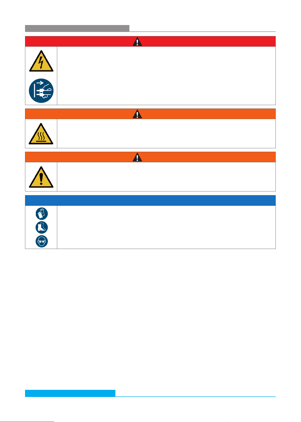
1.3.2 Symbols
The following symbols indicate notes which are not safety-relevant but increase the intelligibility of the documentation.
Table 3: Meaning of symbols
Symbol Meaning
If this information is not observed, the product cannot optimally be used or operated.
>Singular, independent action step / instruction
1.
2.
3.
Numbered instruction
The numbers indicate that the action steps follow one another.
This symbol indicates danger to equipment, material and environment.
This symbol indicates the risk of personal injury (minor injury).
This symbol indicates the risk of personal injury (death, serious bodily injury).
This symbol specifies that protective gloves should be worn.
This symbol specifies that safety shoes should be worn.
This symbol specifies that protective goggles should be worn.
This symbol specifies that the unit should be disconnected from the power supply.
This symbol indicates possible hazards to the environment.
1.3.3 Terms
In this documentation the following terms are used:
Table 4: Terms
1.3.4 Abbreviations
In this documentation the following abbreviations are used:
Table 5: Abbreviations
Term Meaning
FNA1 Off-line Filter Unit
Term Meaning

Subject to change · 0324· EN
Page 6 www.argo-hytos.com
2 Safety instructions
2.1 About this chapter
This product was manufactured according to the generally recognized standards of engineering. Nevertheless, there is a danger of
injury or damage if you do not observe this chapter and the safety instructions in this documentation.
›Read this document thoroughly and completely before working with the product.
›Retain this document and ensure that it is available for all users at all times.
›Always include the necessary documentation when passing the equipment along to a third party.
2.2 Intended use
This product is a hydraulic component.
You may use the product for the following:
›for filtration of hydraulic fluids in the bypass flow on machines and systems, taking account of the technical data.
›This product is intended for professional use only and not for private use.
"Intended use" also includes that you have completely read and understood this documentation, in particular Chapter 2
"Safety instructions".
2.3 Improper use
Any other use than the intended use described, is improper and inadmissible.
If unsuitable products are installed or used in safety-related applications, unintended operating states may occur in the application,
which may cause personal injury and / or property damage.
Therefore only use this product in safety-related applications if this use is explicitly specified and permitted in the product documentation,
e.g. in explosion protection areas or in safety-related parts of a control system (functional safety).
ARGO-HYTOS assumes no liability for damages resulting from improper use. The risks associated with improper use are solely with
the user.
2.4 Reasonably foreseeable misuse
The delivery of the following media is forbidden:
›others than listed in Chapter 16 “Technical data“.
Especially
›flammable liquids such as petrol or thinner (explosion hazard)
›foodstuffs
›The device is not suitable for sucking sludge and sediment.
The operator alone is liable for damages resulting from improper use.
2.5 Qualification of personnel
The operations described in this document require fundamental knowledge of mechanics and hydraulics as well as knowledge of the
appropriate technical terms. In order to ensure safe use, these operations may therefore only be carried out by a correspondingly
skilled worker or an instructed person under the guidance of a skilled worker.
A skilled worker is someone who can - based on his / her technical education, knowledge and experience as well as knowledge of
the respective regulations of the jobs assigned to him / her - recognize possible dangers and ensure appropriate safety measures.
A skilled worker must observe the relevant technical regulations.

Subject to change · 0324· EN
Page 7
www.argo-hytos.com
2.6 General safety instructions
›Observe the valid regulations for accident prevention and environmental protection.
›Observe the safety regulations and requirements of the country in which the product is used / applied.
›Only use ARGO-HYTOS products that are in technically perfect condition.
›Observe all instructions on the product.
›People who assemble, operate, disassemble or maintain ARGO-HYTOS products may not do so under the influence of alcohol,
other drugs or medications that affect the responsiveness.
›Only use manufacturer-approved accessories and spare parts, in order to prevent personal danger due to unsuitable
spare parts.
›Observe the technical data and ambient specifications specified in the product documentation.
›If unsuitable products are used or installed in safety-relevant applications, unintended operating states may occur in the application,
which can cause personal injury and / or material damage. Therefore only use the product in safety-relevant applications if this use
is explicitly specified and permitted in the product documentation.
›You may only put the product into operation, when it has been established that the final product (e.g. a machine or system), into
which the ARGO-HYTOS products have been installed, complies with the country-specific regulations, safety regulations and
standards of the application.
2.7 Product and technology related safety instructions
Leaked hydraulic oil
Environmental hazard / risk of slipping.
›In case of spills, cover the oil-covered surface immediately with an oil-binding medium.
›Then immediately dispose of the oil-binding medium according to the national environmental regulations.
Ignition hazard
Risk of electrostatic charge by poorly conducting hydraulic fluid.
›If the electrical conductivity of the hydraulic fluid is not known, please contact the manufacturer of the
hydraulic fluid.
Risk of burns
Contact temperatures according to DIN EN563 (3) and DIN EN13202 (4) may be exceeded during
operation.
›Allow the off-line filter unit to cool down before touching it.
CAUTION

Subject to change · 0324· EN
Page 8 www.argo-hytos.com
Danger due to improper handling
Property damage
› The off-line filter unit FNA1 008 / FNA1 016 may only be used in accordance with
Section 2.2, “Intended use”.
Leakage or spillage of hydraulic fluid
Environmental pollution and ground water contamination.
›Use oil binding agents in order to bind leaked hydraulic oil.
Risk of burns
Contact temperatures according to DIN EN563 (3) and DIN EN13202 (4) may be exceeded during
operation.
›Allow the off-line filter unit to cool down before touching it.
Contamination due to fluids and foreign bodies
Premature wear, malfunction, risk of damage, property damage.
›Ensure cleanliness during installation in order to prevent foreign bodies, such as welding beads or metal chips,
from entering the hydraulic lines, leading to premature wear or malfunction.
›Make sure that connections, hydraulic lines and attachment parts (e.g. gauges) are free from dirt and chips.
›Prior to commissioning, check that all hydraulic and mechanical connections are connected and tight,
and that all gaskets and seals of the plug connectors are correctly assembled and undamaged.
›For removal of lubricants and other contaminants, use residue-free industrial wipes.
›Make sure that all connections, hydraulic lines and attachment parts are clean.
›Ensure that no contaminants enter when closing the connections.
›Make sure that no detergents enter the hydraulic system.
›Do not use cotton waste or faying cleaning rags for cleaning.
›Do not use hemp as sealing agent.
Improper cleaning
Premature wear, malfunction, risk of damage, property damage.
›Close all openings with appropriate protective fittings to prevent penetration of detergents.
›Do not use aggressive cleaning agents for cleaning. Clean the product with a suitable cleaning fluid.
›Do not use a high pressure cleaner.
›Do not use compressed air to clean function interfaces such as seal areas.
3 General instructions
CAUTION
3.1 For prevention of material damage and product damage

Subject to change · 0324· EN
Page 9
www.argo-hytos.com
4 Scope of delivery
The package includes:
›1 Off-line Filter Unit FNA1 008 / FNA1 016
›1 Operating manual
›Mounting kit (rubber buffers, washers, nuts)
Subject to change · 0324· EN
Page 10 www.argo-hytos.com
5 About this product
The off-line filter unit “FNA1 008 / FNA1 016“ is a filter system for filtering hydraulic fluids in the bypass flow.
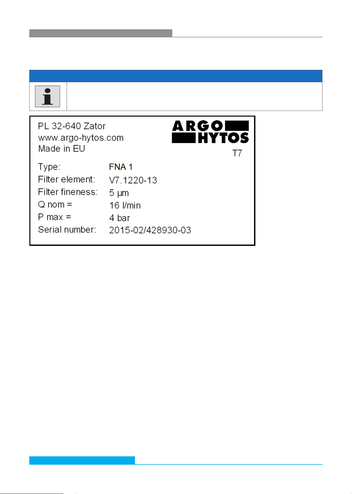
5.1 Type plate
Fig. 1: Type plate (example)
Type plates are documents; they must not be modified or removed.
›Damaged or lost type plates must be replaced with exact copies of the original.
NOTE
Subject to change · 0324· EN
Page 11
www.argo-hytos.com
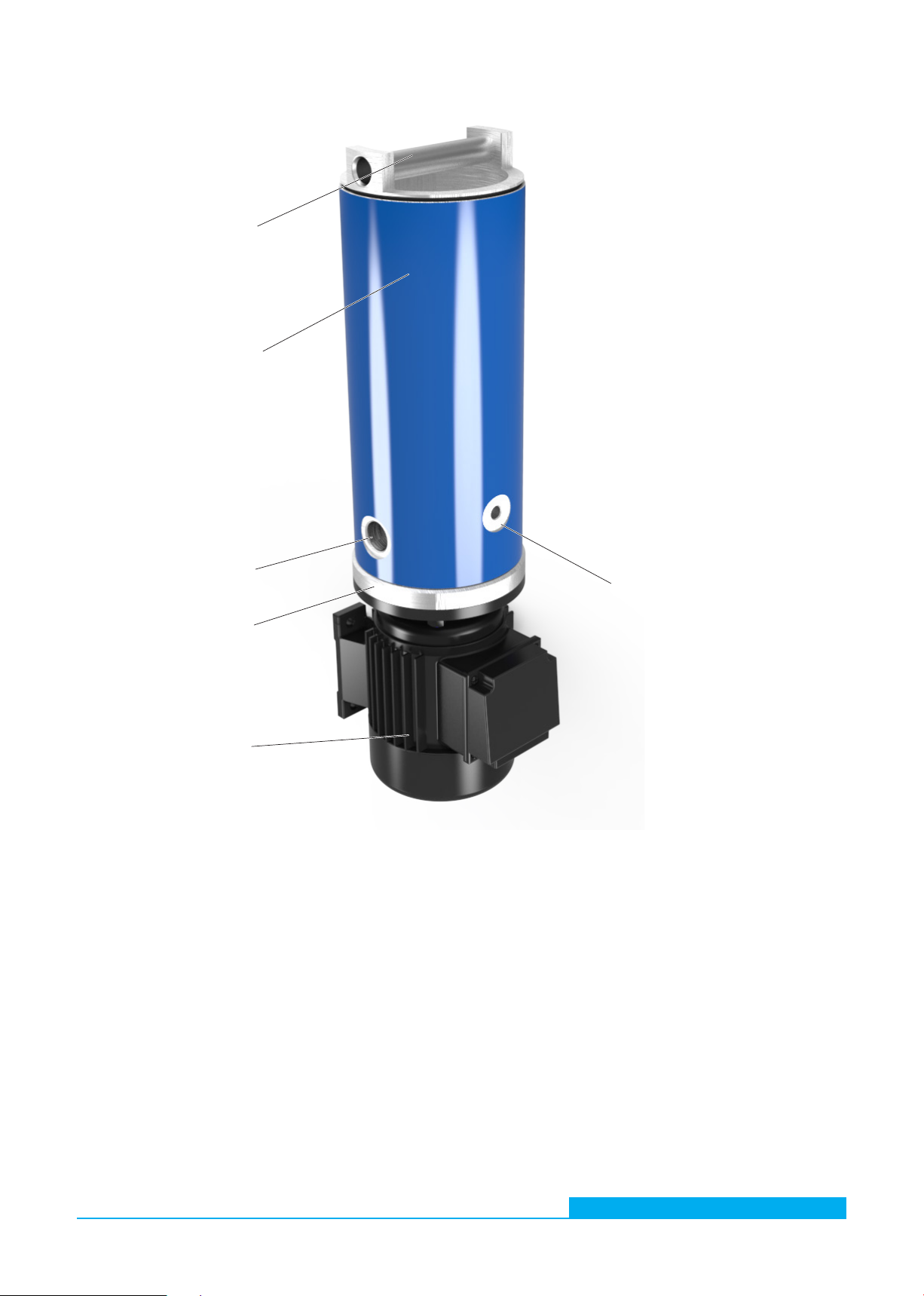
5.2 Component overview
Fig. 2: Component overview
1 Filter cover 5 Oil inlet port (outlet port located
on the opposite side of the filter
housing)
2 Filter housing 6 Hydraulic pump
3 Filter element 7 Electric motor
4 Connection for clogging indicator
(connection type: port M12x1.5
or flange depending on the
version of the unit
5
7
6
2, 3
1
4

Subject to change · 0324· EN
Page 12 www.argo-hytos.com
6 Transport and storage
This chapter contains information on the transport, setting up, connecting and putting into operation as well as storage of the unit.
6.1 Transport
›The unit is not suitable for transport
6.2 Storage
6.2.1 Preparation for storage
›The unit must be completely emptied.
›Treat all bare parts with preservatives.
6.2.2 Storage
›Do not store the unit near flammable liquids or gases.
›Do not store in the rain or in damp and wet environment.
To be observed:
›The safety instructions in chapter “Safety information“ and here particularly the operating conditions in section
“Intended use“.
›Dimensions and weight of the unit in chapter “Technical data“.
NOTE
Subject to change · 0324· EN
Page 13
www.argo-hytos.com
7 Installation
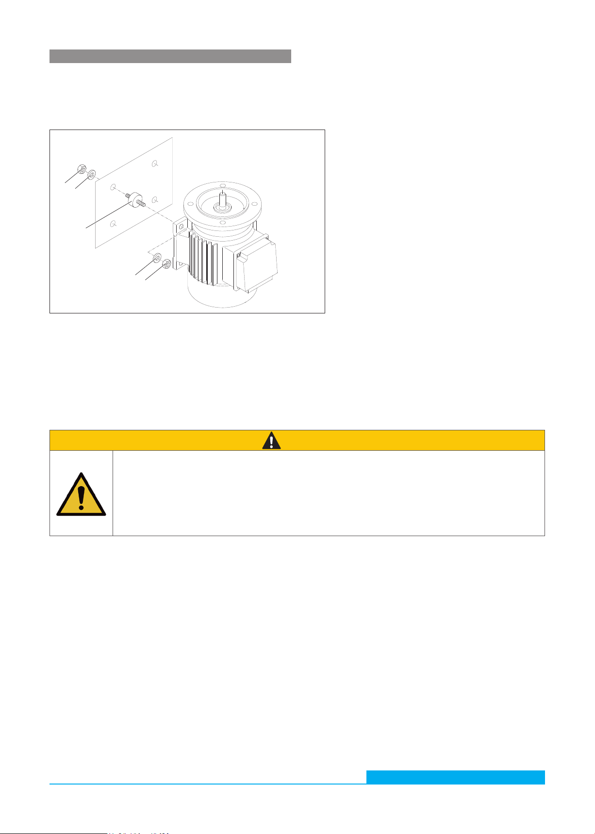
7.1 Mounting kit
The unit must be fixed sufficiently safe and vibration-free by using the provided mounting kit (tightening torque of the hexagon nuts
(3): MA5+2 Nm – AF 10).
60%ArgoHytos FNA008/016 Montagesatz
7.2 Hydraulic connection
Fig. 3: Mounting kit
Risk of malfunctions!
›When hydraulically connecting the off-line filter unit, a strainer must be used on the suction side.
›A missing suction strainer can lead to destruction of the pump. In this case, the manufacturer assumes no
liability.
›With installation of the off-line filter units, a clogging indicator must be used.
›Without a clogging indicator, element contamination is not detectable.
CAUTION
1 Damping element (4x) 3 Hexagon nut AF10 (8x)
2 Washer (8x)
2
3
3
2
1

Subject to change · 0324· EN
Page 14 www.argo-hytos.com
7.3 Mains connection
Danger to life through electric shock!
›Electrical work may only be carried out by qualified electricians.
›The mains voltage must match the voltage indicated on the type plate (motor).
›The direction of rotation of the motor must match the direction of the rotation arrow on the motor housing.
›Check the direction of rotation of the motor each time the unit is switched on (only for three-phase motor).
›The power source must be sufficiently fused (see page 23).
›Cable cross-sections must be sufficiently dimensioned.
›Cables and connection to the power source must be in perfect condition.
DANGER
Always observe before operating the filter unit:
›The above-mentioned operating conditions (see page 19) must be strictly observed.
›Read the installation instructions carefully and completely.
›Cables and hoses must not be laid within the operating personnel's range of movement (risk of tripping).
›During unattended operation, make sure that hoses cannot fall out of the tank.
›Ensure that the suction and pressure sides are sufficiently immersed in hydraulic fluid (sucking in air can lead to malfunctions).
›If no air is sucked in during commissioning, open the cover on the filter housing and fill in approx. 0.3 l of oil.
›The oil must be compatible with the operating fluid from the previous filtrations. If this is not the case, the filter system must be
cleaned and the filter element must be replaced.
›The cover of the filter housing must be properly closed. If necessary, turn the cover by hand as far as it will go; there may be a gap
that remains visible between the cover and the housing (see fig. 4)
Fig. 4: Gap between cover and housing
On start-up please check:
›Tightness of the filter unit.
›For 3-phase AC motors, check whether the motor‘s direction of rotation corresponds to the direction of the rotation arrow on the
motor housing. If not, only allow qualified personnel to invert the phases (only with 3-phase motor).
In the event of power failure
›Switch the unit off or disconnect it from the mains to avoid consequential damage to people and the environment when the
voltage returns, e.g. due to overflowing oil or danger of slipping due to leaking oil.
Gap

Subject to change · 0324· EN
Page 15
www.argo-hytos.com
8 Installation recommendations
Risk of malfunctions!
›When connecting the off-line filter unit hydraulically, a strainer must be inserted on the suction side.
›A missing strainer can lead to the destruction of the pump. In this case, the manufacturer assumes no liability.
›When installing the off-line filter units, a contamination indicator must be used.
›Without a clogging indicator, element clogging cannot be detected.
CAUTION
Device type FNA1 008 / FNA1 016
Installation position Vertical
Fixing Mounting only by using the supplied mounting kit (MA5+2 Nm)
Clearance filter element min. 340 mm
Recommended connection for piping All cutting and progressive ring fittings of the series L or LL from Parker (ERMETO
Original) EO-standard program according to DIN 2353/ISO 8434-1
Recommended connection for hoses
suction connection - ø (inlet)
min. DN 25 and max. -0.4 bar negative pressure
Recommended connection for hoses
pressure connection - ø (outlet)
min. DN 20
Suction height max. 1.5 m
Pump protection Min. fineness 600 µm e.g. order no. FA 016.0301S7
Max. cleaning performance Keep the distance between suction and pressure side as large as possible (no short-
circuit of oil flow)
Table 6: Installation recommendations
Subject to change · 0324· EN
Page 16 www.argo-hytos.com
9 Operation of the off-line filter unit
9.1 Filtering hydraulic fluids in the bypass flow
›Attach the filter unit as described under point 7 and connect it (with 3~ motors observe direction of rotation).
›When using a suction bell or a suction and pressure lance resp., immerse these into the hydraulic tank of the machine or system.
›Depending on the connection, the filter unit can be switched on automatically (with the machine or system) or manually.
›Control of the oil flow (sufficient immersion depth of the strainer or the suction lance in the hydraulic fluid).
›Check the element for clogging, using the clogging indicator.
Risk of malfunctions!
›When connecting the off-line filter unit hydraulically, a strainer must be inserted on the suction side.
›A missing strainer can lead to the destruction of the pump. In this case, the manufacturer assumes no liability.
›When installing the off-line filter units, a contamination indicator must be used.
›Without a clogging indicator, element clogging cannot be detected.
CAUTION
9.2 Ensuring maximum cleaning performance
›Start up the hydraulic or lubrication system (circulation of fluid, lower viscosity).
›Keep the distance between the suction and pressure sides as large as possible (no short-circuiting of the oil flow).
›Keep an adequate filtration time - recommended guideline values:
60 minutes per 100 l / 26.4 gal tank capactiy with FNA1 008 devices
30 minutes per 100 l / 26.4 gal tank capacity with FNA1 016 devices
›At the beginning of filtration, it may take a few seconds to fill the filter unit.
›To prevent an oil flow short circuit, the distance between the suction bell or the suction and pressure lances
should be kept as large as possible.
NOTE

Subject to change · 0324· EN
Page 17
www.argo-hytos.com
10 Technical data
›For device-specific technical data, please see ordering code on page 18 and table 8 on page 19.
NOTE
FNA1 008 FNA1 016
Nominal flow rate 8 l/min (50 Hz) or 9.5 l/min (60 Hz) 16 l/min (50 Hz) or 19 l/min (60 Hz)
Pressure relief valve 4 ± 0.5 bar
Filter element see page 18
Clogging indicator on request, see page 18
Connections see page 15 - table 6
Suction strainer
(optional)
fineness 600 µm
Electric drives see page 18
FNA1 008 / 23050 1~ AC motor with operating capacitor, 220-240 V, 50/60 Hz, 0.25 kW/0.30 kW; n = 1500/1800 min–1
FNA1 008 / 40050 3~ three-phase motor, 400/460 V, 50/60 Hz, 0.25 kW/0.30 kW; n = 1500/1800 min–1
FNA1 008 / 11050 1~ AC motor with operating capacitor, 110-120 V, 50/60 Hz, 0.25 kW/0.30 kW; n = 1500/1800 min–1
FNA1 016 / 23050 1~ AC motor with operating capacitor, 220-240 V, 50/60 Hz, 0.45 kW/0.55 kW; n = 3000/3600 min–1
FNA1 016 / 40050 3~ three-phase motor, 400/ 460 V, 50/ 60 Hz, 0.45 kW/0.55 kW; n = 3000/ 3600 min–1
FNA1 016 / 11050 1~ AC motor with operating capacitor, 220-240 V, 50/60 Hz, 0.45 kW/0.55 kW; n = 3000/3600 min
Weight when empty approx. 11 kg
Noise intensity level max. 73 dB(A) under operating conditions allowed for continuous operation
max. 79 dB(A) under operating conditions allowed for short-term operation
Table 7 : Technical data

Subject to change · 0324· EN
Page 18
www.argo-hytos.com
10.1 Technical data depending on the ordering code
Type of filter unit Code
Off-line filter unit FNA1
FNA1 -
Nominal flow rate* Code
8 l/min / 2.11 gpm 008
16 l/min / 4.23 gpm 016
Filter element Code
Fineness (β=200)
Dirt-holding capacity according to
ISO 16889 / water capacity
Filter
element
FNA1 008 FNA1 016
EXAPOR®MAX 2 3 µm 490 g 280 g V7.1220-113 V003
EXAPOR®MAX 2 5 µm 460 g 270 g V7.1220-13 V005
EXAPOR®MAX 2 10 µm 340 g 190 g V7.1220-06 V010
EXAPOR®AQUA 7 µm 145 g / 320 ml 85 g / 190 ml Y7.1220-05 Y007
EXAPOR®AQUA 3 µm 165 g / 340 ml 105 g / 205 ml Y7.1220-113 Y003
/
Electric motor*
(other motor on request)
Code
Phase(s), voltage Frequency Power
FNA 1 008 / 016
Electric
connection
Dimensions
type no.
3~400/460 VAC 50/60 Hz 0.25 / 0.45 kW 1 1 or 3 40050
1~230 VAC 50/60 Hz 0.25 / 0.45 kW 2 2 or 4 23050
1~110 VAC 50/60 Hz 0.25 / 0.45 kW 2 2 or 4 11050
* Indications at 50 Hz. At 60 Hz, the value increases by approx. 20%.
For version with DC motor, 24 or 12 V see data sheet FNA 014 no. 80.35
Connection port Code
Size Dimensions type no.
In: G¾
Out: G½ 1 or 2 G
In: 11/16-12 UN-2B
Out: 3/4-16 UN-2B 3 or 4 U
Clogging indicator Code
Type Code of
indicator
Data sheet
no.
Connection Hydraulic
symbol
Manometer optical DG 200-16 60.20 M12 x 1.5 1 O
Pressure switch electrical DG 813-21 60.20 M12 x 1.5 2 E
Pressure switch optical / electrical DG 815-12 60.20 M12 x 1.5 3 EO
without indicator M12 x 1.5 4 X
Differential
pressure
clogging indicator
optical DG 042-01 60.30 Flange 5 OD
electrical DG 041-31 60.30 Flange 6 ED
electrical + optical DG 041-44 60.30 Flange 7 EOD
without indicator Flange 8 XD
-

Subject to change · 0324· EN
Page 19
www.argo-hytos.com
11 Operating conditions
Permissible temperature range Hydraulic fluid: 0 °C to 60 °C / 32 °F to 140 °F
Environment: 0 °C to 50 °C / 32 °F to 122 °F
Permissible viscosity range Type of unit Continuous operation
min.
Continuous operation
max.
Short-term operation
max.
FNA1 008 15 mm2/s 250 mm2/s 400 mm2/s
FNA1 016 15 mm2/s 250 mm2/s 400 mm2/s
Permissible suction heights max. 1 m (unfilled)
max. 6 m (in operating condition)
Media resistance Resistant to environmentally friendly and mineral oil based fluids.
In case of synthetic fluids, please consult the manufacturer.
Mains fuse 230 V, 50/60 Hz 10 A – 16 A
110 V, 50/60 Hz 10 A – 16 A
400/460 V, 50/60 Hz 10 A – 16 A
Working position upright
Table 8: Operating conditions
Subject to change · 0324· EN
Page 20 www.argo-hytos.com
12 Maintenance
Danger to life through electric shock!
›Disconnect the device from the power supply during maintenance work.
›Electrical work may only be carried out by qualified electricians.
DANGER
Hot surfaces - danger of burns!
›Let the filter unit cool down and empty it completely before maintenance.
WARNING
›When replacing the pump / motor, proceed with special care.
›All parts coming into contact with the hydraulic medium must be kept free of dirt and chips.
›If dirt enters the pump during maintenance work, optimal functioning of the device is no longer guaranteed.
In this case, the manufacturer assumes no liability!
WARNING
When performing any work:
›Wear protective gloves, safety shoes and safety goggles!
NOTE
This manual suits for next models
1
Table of contents
Popular Water Filtration System manuals by other brands

Atlantic Ultraviolet
Atlantic Ultraviolet Mighty Pure MP16A owner's manual

SunSun
SunSun CBG-500 Operation manual

Hayward
Hayward XStream Filtration Series owner's manual

Contech
Contech DownSpout StormFilter Operation and maintenance

Teka
Teka Airfilter MINI operating instructions

Wisy
Wisy LineAir 100 Installation and operating instructions

Schaffner
Schaffner Ecosine FN3446 Series User and installation manual

Pentair
Pentair FLECK 4600 SXT Installer manual

H2O International
H2O International H20-500 product manual

Renkforce
Renkforce 2306241 operating instructions

Neo-Pure
Neo-Pure TL3-A502 manual

STA-RITE
STA-RITE VERTICAL GRID DE FILTERS S7D75 owner's manual


