VOKERA BeSMART User manual

IT GUIDA RAPIDA
EN QUICK START GUIDE
TermosTaTo / ThermosTaT
cod. BeSMART_GR rev. 0 11/16
BeSMART
WPS/Smartlink Outputs Boiler
SET
PROG
RESET
ESC
MODE

2ENIT
INSTALLAZIONE AINSTALLATION A
BeSMART: cablato in ON/OFF / Wi-
red ON/OFF
WiFi Box: NON cablato (solo alimen-
tato) / Wireless (only main supply)
In questa congurazione l’installa-
zione OTBus non è realizzabile. / In
this installation the OTBus congu-
ration is not working.
WiFi Box
RF
internet
WiFi WiFi
230 V
TA
SET
PROG
RESET
ESC
MODE
BeSMART
BeSMART
server
TA
INSTALLAZIONE BINSTALLATION B
BeSMART: NON cablato (wireless)/
NOT cabled (Wireless)
WiFi Box: Cablato/ Wired
TA
WiFi Box
BeSMART
serverinternet
WiFi WiFi
RF
RF
230 V
SET
PROG
RESET
ESC
MODE
BeSMART
WiFi Box
BeSMART
RF
SET
PROG
RESET
ESC
MODE
BeSMART
serverinternet
WiFi WiFi
230 V
RF
OT
Nota: per tutte le altre tipologie installative consultare il manuale installatore .
Note: ffor all other types of different installation refer to the installer manual.

3ENIT
AVVERTENZE GENERALI GENERAL NOTICES
A Evitare correnti d’aria
BNon installare sopra fonti di calore
CEvitare luce diretta del sole
DPosizionare ad altezza adeguata
Prima dell’installazione
•Vericare che il termostato sia com-
patibile con la caldaia (consultare
manuale installatore caldaia).
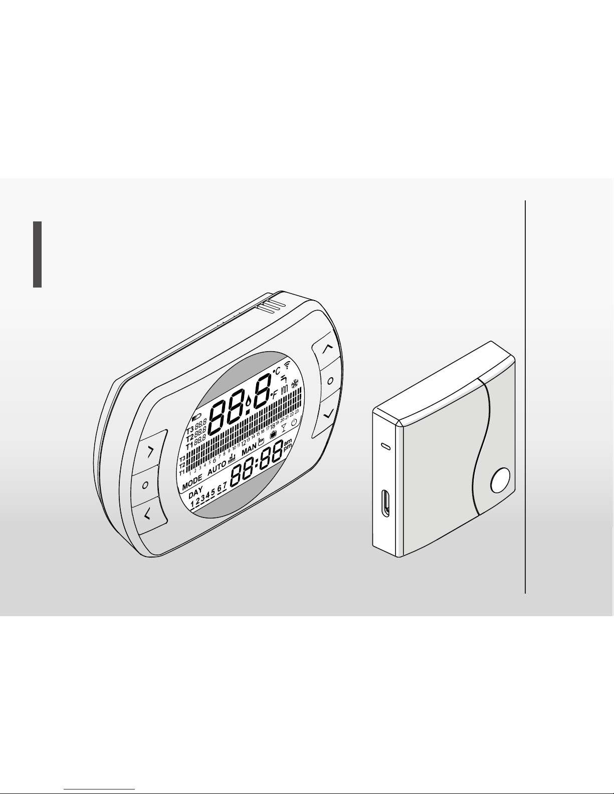
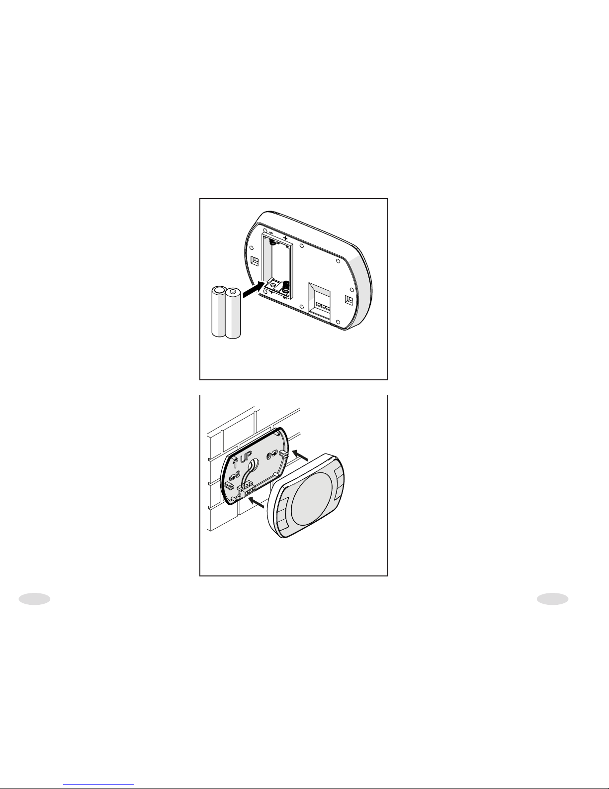
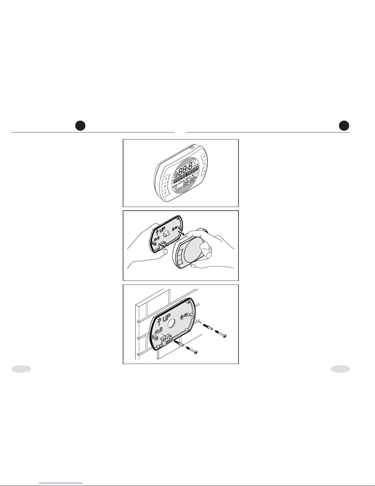
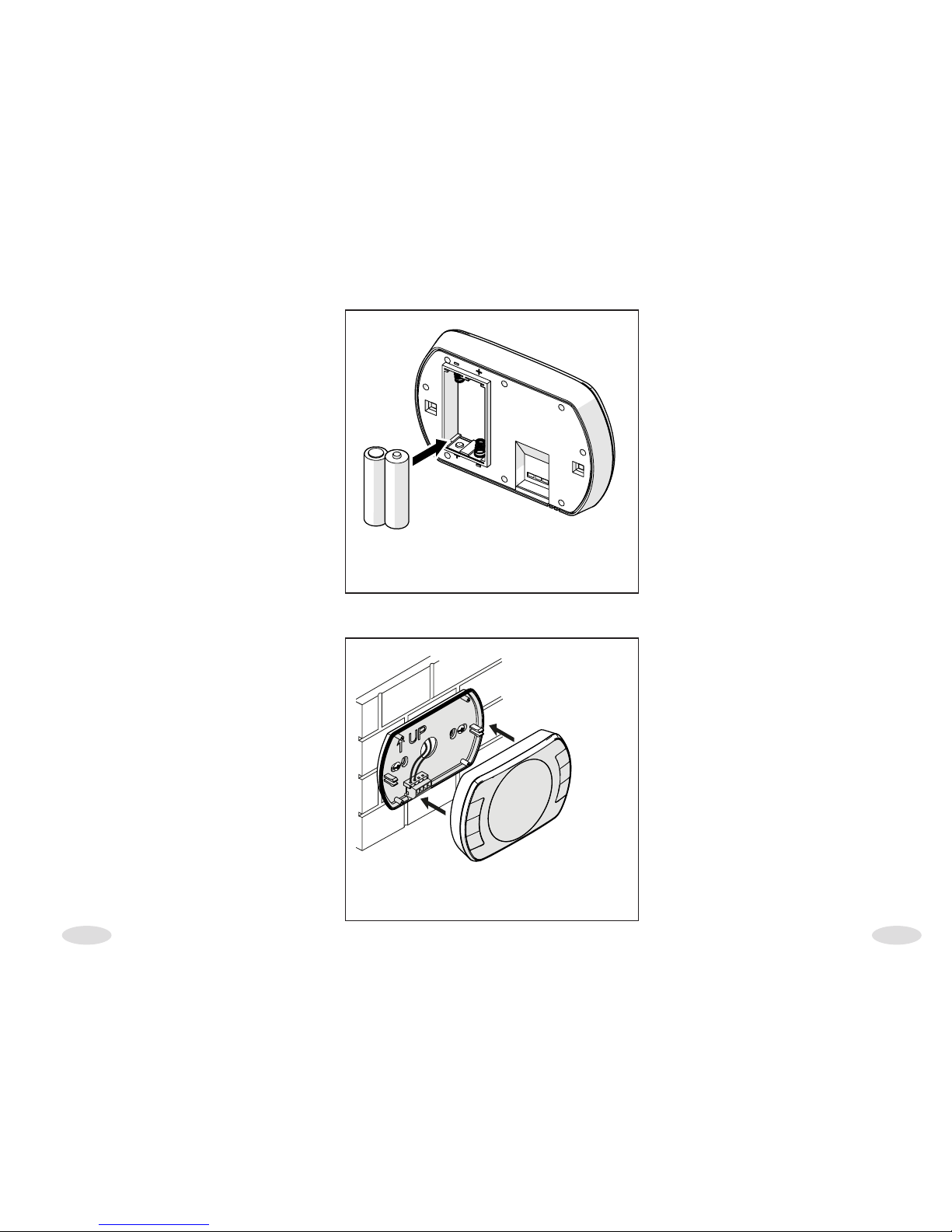
• Il termostato BeSMART wireless
può essere installato ovunque, è tut-
tavia consigliabile stabilire il punto
più idoneo (vedi immagini correlate).
L’installazione wireless non necessi-
ta di cablaggio pertanto l’operazio-
ne risulta estremamente semplice.
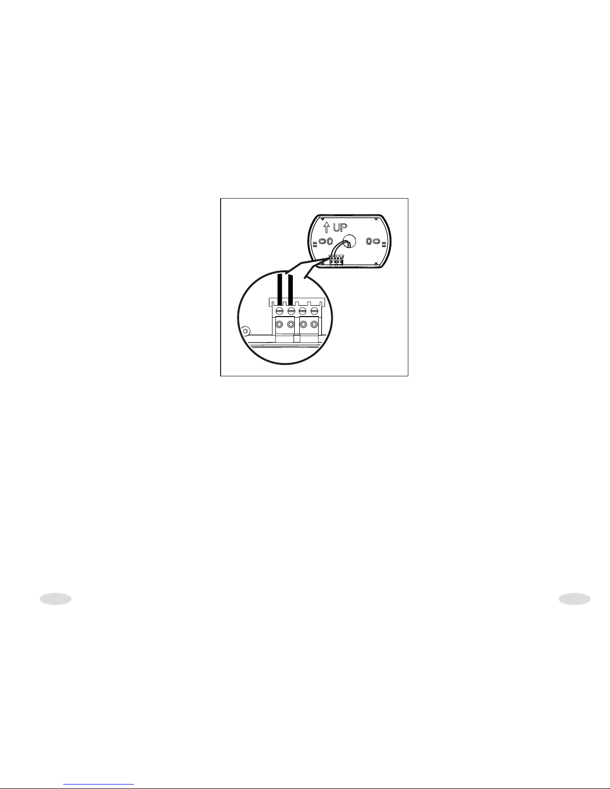
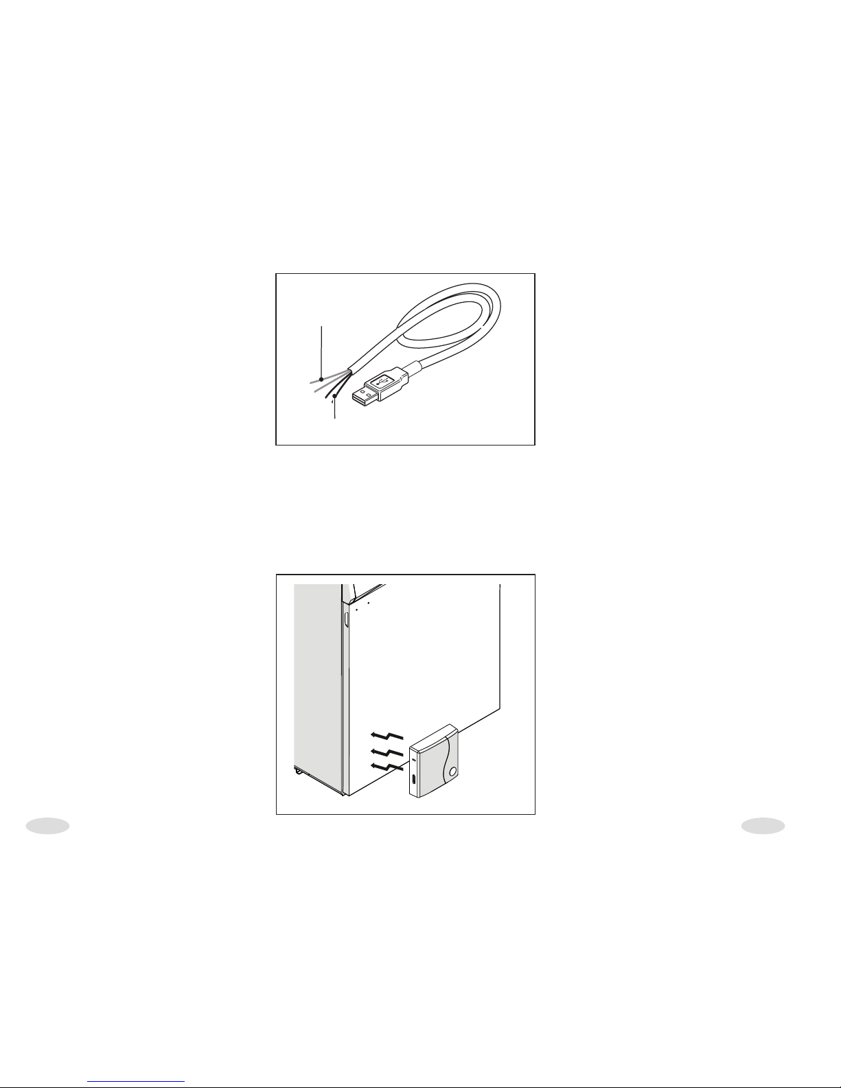
•Il termostato BeSMART può essere
installato anche cablato in sostitu-
zione di un qualsiasi termostato già
esistente, previa verica della com-
patibilità (consultare manuale instal-
latore BeSMART).
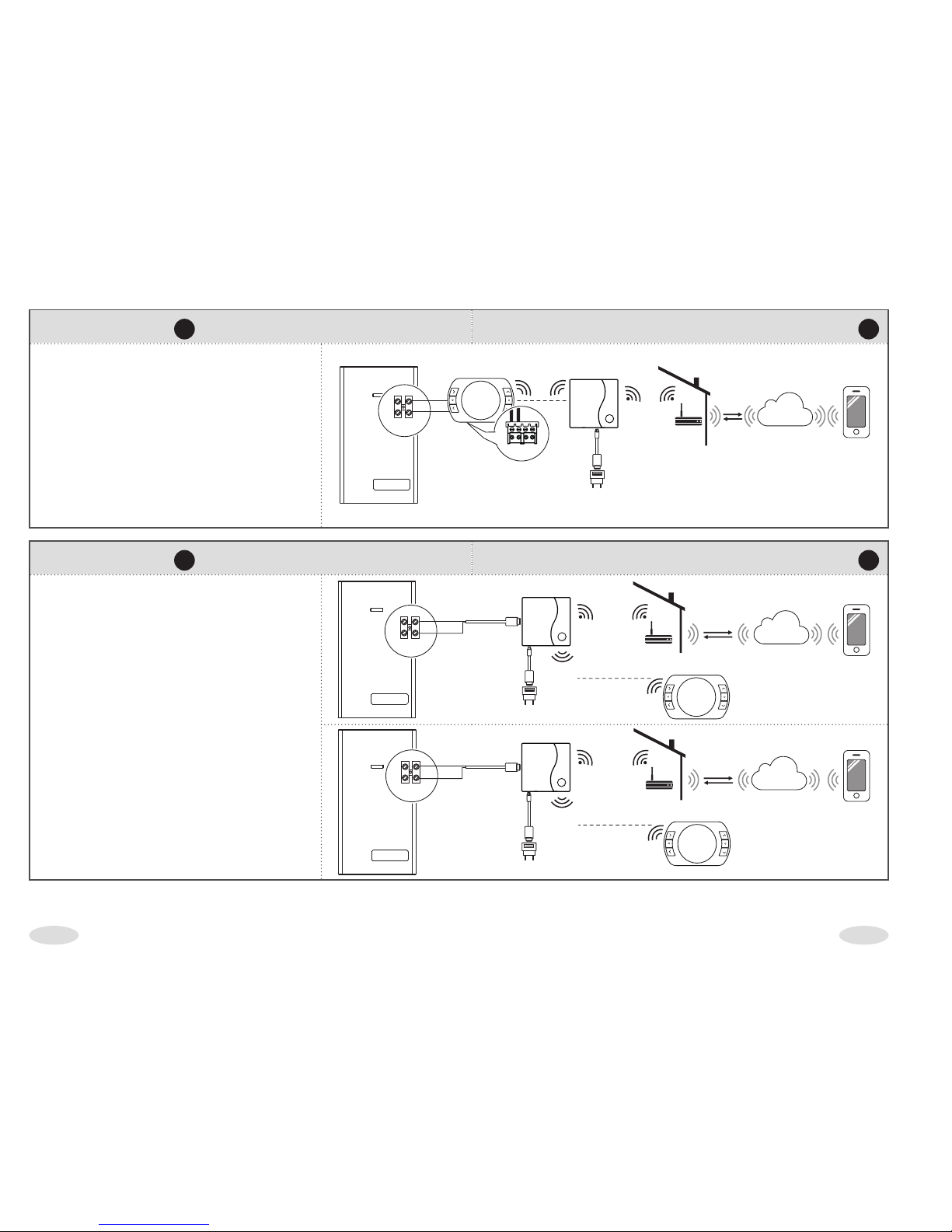
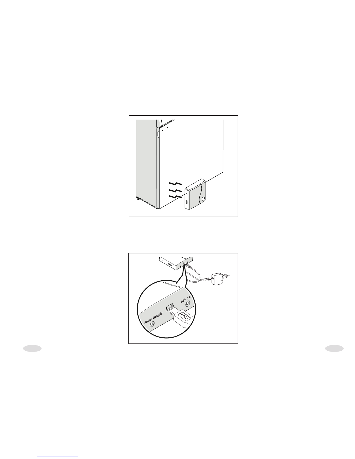
•Prima di procedere all’installazione
del modulo di comando della calda-
ia (WiFi Box) interrompere l’alimenta-
zione della caldaia.
Sono necessari i seguenti attrezzi:
•Cacciavite a croce
•Piccolo cacciavite a taglio
•Pinza e pinza spella li
AAvoid draughty areas
BDo not install above heat sources
CAvoid direct sunlight
DInstall at the correct height
Before installation
•Refer to the appliance manual
to ensure that the BeSMART
thermostat is compatible with your
boiler.
•The BeSMART wireless thermostat
can be installed almost everywhere
within the home, however please
refer to the adjacent diagrams
for guidance when deciding on a
suitable location.
•The BeSMART thermostat can
also be used to replace an existing
hard-wired thermostat (please
check appliance manual to ensure
compatibility).
•Switch off and isolate the appliance
and any external controls from the
electrical supply, before carrying out
the installation.
Tools required for the installation
•Phillips screwdriver
•Small at blade screwdriver
•Combination pliers
SET
PROG
RESET
ESC
MODE
1,5m
SET
PROG
RESET
ESC
MODE
SET
PROG
RESET
ESC
MODE
SET
PROG
RESET
ESC
MODE
A B
C D

4ENIT
INSTALLAZIONE AINSTALLATION A
SET
PROG
RESET
ESC
MODE
Installazione BeSMART
Se necessario rimuovere il vecchio
apparecchio.
9 Vericare la compatibilità (con-
sultare manuale installatore
BeSMART) e procedere al col-
legamento.
Separare il BeSMART dalla sua base.
Fissare la base del BeSMART alla pa-
rete o alla scatola elettrica utilizzando
le viti a corredo (testa della vite dentro
propria sede).
BeSMART installation
If necessary remove the old
thermostat.
9 If its intended to re-use any
existing wiring; you should refer
to the appliance manual to
ensure compatibility .
Separate the BeSMART from the wall
plate.
Fix the wall plate to the wall using the
supplied screws (screw head inside
proper location).

5ENIT
Collegare i cavi del termostato am-
biente di caldaia o l’alimentazione
dell’eventuale valvola di zona al mor-
setto TA del BeSMART.
9 Per i collegamenti elettrici e le
speciche tecniche vi invitiamo
a consultare il manuale installa-
tore del BeSMART.
If using as a hard-wired control;
connect the respective wiring to the
relevant terminals on the BeSMART
control.
9 Please refer to the appliance
installation manual and the
BeSMART manual for specic
information on hard-wired
connections.
TA
ON/OFF

6ENIT
AA
AA
Inserire le due batterie di tipo AA for-
nite a corredo, nell’apposito alloggia-
mento.
9 Inserire le batterie con la corretta
polarità come indicato in gura.
Montare il BeSMART sulla sua base
semplicemente premendo legger-
mente sullo stesso.
Insert two ‘AA’ type batteries
(supplied), into the battery
compartment.
9 Insert the batteries, observing
the correct polarity as indicated.
Re-attach the BeSMART thermostat
to the wall plate by aligning and
then pressing rmly around the outer
edges.

7ENIT
Installazione WiFi Box
Applicare il WiFi Box sul mantello
metallico della caldaia mediante ma-
gnete presente sul retro dello stesso
(si consiglia di vericare la minima
temperatura esterna di installazione
riportata sul manuale installatore del
BeSMART).
In caso di segnale WiFi debole o as-
sente presso la caldaia, si consiglia
l’installazione dell’accessorio WiFi Ex-
tender oppure l’utilizzo dell’accesso-
rio ricevitore RF caldaia e posizionare
il WiFi Box in una zona con segnale
buono (consigliato sopra il 40%).
Alimentare il WiFi Box tramite l’appo-
sito cavo e alimentatore forniti a cor-
redo.
WiFi Box installation
Attach the WiFi box to the appliance
casing, using the magnetic pad
located on the rear of the WiFi
Box. Please check the ambient
temperature is according the product
specication as indicated on the
installation manual.
In case of low or null WiFi signal
and with boiler RF receiver or WiFi
Extender installed, place the WiFi Box
in an ambient with a good WiFi signal
(above 40%).
Using the mini USB cable and power
adaptor (supplied); connect the WiFi
box to an adjacent electrical socket .
WPS/Smartlink Outputs Boiler

8ENIT
INSTALLAZIONE BINSTALLATION B
SET
PROG
RESET
ESC
MODE
Installazione BeSMART
Se necessario rimuovere il vecchio
apparecchio.
9 Il BeSMART non necessita di
essere cablato perchè wireless.
Si consiglia di isolare i cavi e farli
rientrare nella parete.
Separare il BeSMART dalla sua base.
Fissare la base del BeSMART alla pa-
rete o alla scatola elettrica utilizzando
le viti a corredo (testa della vite dentro
propria sede).
BeSMART installation
If necessary remove the old
thermostat.
9 The BeSMART thermostat is
a wireless control. Isolate any
redundant wiring and ensure
it does not interfere with the
tments of the BeSMART
control.
Separate the BeSMART from the wall
plate.
Fix the wall plate to the wall using the
supplied screws (screw head inside
proper location).

9ENIT
AA
AA
Inserire le due batterie di tipo AA for-
nite a corredo, nell’apposito alloggia-
mento.
9 Inserire le batterie con la corretta
polarità come indicato in gura.
Montare il BeSMART sulla sua base
semplicemente premendo legger-
mente sullo stesso.
Insert two ‘AA’ type batteries
(supplied), into the battery
compartment.
9 Insert the batteries, observing
the correct polarity as indicated.
Re-attach the BeSMART thermostat
to the wall plate by aligning and
then pressing rmly around the outer
edges.

10 ENIT
TA
OT
Installazione WiFi Box
Collegare i li del cavo USB del WiFi
Box al morsetto OTBus (solo per spe-
ciche caldaie) oppure al TA (Termo-
stato Ambiente-ON/OFF) della calda-
ia.
9 Per i collegamenti elettrici e le
speciche tecniche vi invitiamo
a consultare il manuale installa-
tore di caldaia (connettore OT
per speciche caldaie fornito a
corredo).
Applicare il WiFi Box sul mantello
metallico della caldaia mediante ma-
gnete presente sul retro dello stesso
(si consiglia di vericare la minima
temperatura esterna di installazione
riportata sul manuale installatore del
BeSMART).
In caso di segnale WiFi debole o as-
sente presso la caldaia, si consiglia
l’installazione dell’accessorio WiFi Ex-
tender oppure l’utilizzo dell’accesso-
rio ricevitore RF caldaia e posizionare
il WiFi Box in una zona con segnale
buono (consigliato sopra il 40%).
WiFi Box installation
Connect the (supplied) USB WiFi Box
cable to the boiler OTBus connection
(for specic boilers) or to the boiler
room thermostat connection (TA or
ON/OFF).
9 For the electrical connection
and the technical specications,
please refer to the installation
manual (OT PCB plug supplied
as standard).
Attach the WiFi box to the appliance
casing, using the magnetic pad
located on the rear of the WiFi
Box. Please check the ambient
temperature is according the product
specication as indicated on the
installation manual.
In case of low or null WiFi signal and
with boiler RF receiver or WiFi Ex-
tender installed, place the WiFi Box
in an ambient with a good WiFi signal
(above 40%).
WPS/Smartlink Outputs Boiler

11 ENIT
Collegare la spina USB del cavo pre-
cedentemente collegato alla caldaia
nell’uscita OUTPUTS/BOILER del WiFi
Box.
Alimentare il WiFi Box tramite l’appo-
sito cavo e alimentatore forniti a cor-
redo.
Insert the other end of the USB cable
into the OUTPUTS/BOILER socket of
the WiFi Box.
Using the mini USB cable and power
adaptor (supplied); connect the WiFi
box to an adjacent electrical socket .
WPS/Smartlink Outputs Boiler
USB
Outputs Boiler

12 ENIT
INSTALLAZIONE E CONFIGURAZIONE
DELLA APP PER SMARTPHONE
INSTALLATION AND CONFIGURATION
OF SMARTPHONE APP
Scaricare e installare la APP
BeSMART sul proprio Smartphone o
tablet.
Creare un account utente seguendo
tutti i passaggi indicati sulla APP.
Abbinare il codice ID WiFi del WiFi
Box all’account.
Download and install the BeSMART
APP on your Smartphone or tablet.
Create a user account following the
steps indicated on the APP.
Link your user account to the ‘ID WiFi’
code that’s located on the side of the
WiFi Box.

13 ENIT
MAC: 000000000000
ID WiFi: 0000000000000
WPS/Smartlink Outputs Boiler
A
WiFi Box
Se necessario abbinare in radio fre-
quenza (RF) al WiFi Box altri termosta-
ti e/o ricevitore RF caldaia, premendo
per 5 secondi il tasto trasparente sul
WiFi Box no al lampeggio contem-
poraneo dei LEDs e mettendo nella
medesima modalità la controparte
da abbinare (vedi libretto istruzioni
BeSMART). Terminato l’accoppia-
mento automaticamente il sistema si
riporta alla normalità.
ATasto trasparente a bolla prisma-
tica
If required, it is possible to couple
a boiler receiver or additional
thermostats to the WiFi box using the
following procedure: press and hold
the WiFi LED button on the WiFi box
until both red and green LEDs are
ashing simultaneously. Place the item
that is to be coupled, into the ‘coupling’
mode (see BeSMART instruction
manual). When the coupling process
has been completed, the system will
automatically return to the normal
operating condition.
AWiFi LED button

14 ENIT
WPS/Smartlink Outputs Boiler
Riavviare router WiFi al termine
Restart WiFi router at the end
Associare la password del proprio
modem di casa al WiFi Box sceglien-
do una delle seguenti modalità.
9 Smartphone o tablet devono es-
sere connessi alla rete WiFi a cui
andrà associato il WiFi Box.
Smart Link:
•Premere 1 volta il tasto Smart Link
sul WiFi Box con uno strumento ade-
guato.
•I led verde e rosso iniziano a lam-
peggiare velocemente.
•Selezionare il campo “Congura il
WiFi” nel menu a tendina della APP,
inserire la password del modem di
casa e premere il tasto “Collegati”.
•L’associazione è conclusa se la APP
mostra l’avviso “collegamento effet-
tuato con successo”.
WPS: (solo per modem provvisti di
questa funzione)
•Mettere in modalità WPS il modem
di casa.
•Premere a lungo (5 sec) il tasto WPS
sul WiFi Box con uno strumento
adeguato no a quando i led rosso
e verde dello stesso, lampeggiano
velocemente.
• L’associazione è conclusa se, dopo
pochi secondi, il led rosso del WiFi
Box lampeggia velocemente.
Use the password key of your ‘WiFi’
router to link the WiFi Box to your home
network using one of the methods
indicated below.
9 Smartphones or tablets must be
connected to the WiFI network
that will be matched to the WiFi
Box.
Smart Link:
•Press once the Smart Link button
with a paper clip or similar.
•The green and red LEDs should be
ashing rapidly.
•Start the smart link function on the
app (WiFi conguration menu) enter
the network password – WiFi box will
automatically congure.
WPS: (only for router with WPS
functionality)
•Enable the WPS function via your
router/home network
•Press and hold the WPS button
on the WiFi box with a paper clip
or similar, until the green and red
LEDs are ashing rapidly and
consecutively.
•Successful activation is conrmed
when the red LED ashes rapidly.
9
Il sistema, un vol-
ta on-line, impie-
ga no a 4 minuti
per autocongu-
rarsi.
9
The system,
once online,
may take up to
4 minutes for self
conguration.

15 ENIT
ALLARMI E STATI DI FUNZIONAMENTO ALARMS AND WORKING STATUS
Lista segnalazioni LEDs del WiFi Box e relativa spiegazio-
ne.
LED
verde
LED
rosso Stato
F05 Relè = chiuso
(solo per collegamento ON/OFF)
F1 Relè = aperto
(solo per collegamento ON/OFF)
ON OTBus collegamento = OK
(per collegamento OTBus)
ON F01 Allarme caldaia
(solo per collegamento OTBus)
F05
F1
ON
ON Errore di rete o RF
F05 F05 Modalità WPS attiva – attendere
segnale WPS dal router*
F05 Segnale WPS accettato*
F05 F05 Modalità Smartlink attiva*
F1 F1 Modalità codica RF attiva
* Solo per Wi Box
LED
ON = sso acceso
F05 = lampeggiante veloce (0,5 secs)
F1 = lampeggiante lento (1 secs)
Explanation of status LEDs displayed on WiFi Box.
LED
green
LED
red Status
F05 Relè = bridged
(sonly with ON/OFF installation)
F1 Relè = open
(only with ON/OFF installation)
ON OTBus connection = OK
(OT connection)
ON F01 Boiler alarm
(OTBus connection)
F05
F1
ON
ON Network or RF error
F05 F05 WPS mode in progress (press and
hold WPS button) – wait WPS signal*
F05 WPS signal detected*
F05 F05 Smartlink mode in progress (press
once Smartlink button)*
F1 F1 RF encoding in progress (press and
hold the WiFi LED button)
*Only for WiFi Box
LED
ON = xed ON
F05 = ashing fast (0,5 secs)
F1 = ashing slow (1 secs)

16 ENIT
Lista allarmi BeSMART e relativa azione consigliata.
Allarme Descrizione
Err
Sensore temperatura danneggiato irre-
parabilmente (vedere libretto istruzioni
BeSMART).
E82
Errore radio frequenza
(batterie/distanza da vericare - vedere
libretto istruzioni BeSMART)
E83
Mancanza connessione OTBus
(verica connessione - vedere libretto istru-
zioni BeSMART )
E84
Problemi hardware
(non riparabile - vedere libretto istruzioni
BeSMART)
A01…99 Allarme di caldaia
(ref. manuale caldaia)
Alarm codes indicated on the BeSMART display and
suggested corrective actions.
Alarm Description
Err
Temperature sensor broken.
(not reparable - see BeSMART Instruction
Manual)
E82
Radio frequency error
(Check batteries/distance - see BeSMART
Instruction Manual)
E83
NO OTBus comunication
(Check connections - see BeSMART
Instruction Manual)
E84
Hardware problems
(not reparable, see BeSMART Instruction
Manual)
A01…99 Boiler alarm
(see boiler manual)

17 ENIT

18 ENIT

19 ENIT

BeSMART_GR 0 (11/16)
BeSMART è un brand RIELLO GROUP
BeSMART is a RIELLO GROUP brand
Via Ing. Pilade Riello, 7
37045 Legnago - Italy
Ulteriori informazioni e richiesta
di assistenza al seguente sito:
Further information and request
assistance at the following website:
www.besmart-home.com
Table of contents
Other VOKERA Thermostat manuals