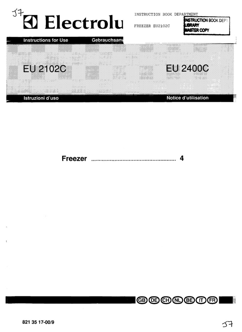
Vollrath Stoelting E157 User manual


This manual provides basic information about the machine. Instructions and suggestions are
given covering its operation and care.
The illustrations and specifications are not binding in detail. We reserve the right to make
changes to the machine without notice, and without incurring any obligation to modify or pro-
vide new parts for machines built prior to date of change.
DO NOTATTEMPT to operate the machine until instructions and safety precautions in this
manual are read completely and are thoroughly understood. If problems develop or questions
arise in connection with installation, operation, or servicing of the machine, contact Stoelting.
Stoelting Foodservice Equipment
502 Highway 67
Kiel, WI 53042-1600
U.S.A.
Main Tel: 800.558.5807
Fax: 920.894.7029
Customer Service: 888.429.5920
Fax: 800.545.0662
© 2014 PW Stoelting, LLC
stoeltingfoodservice.com

Safety Alert Symbol:
This symbol Indicates danger, warning or caution.
Attention is required in order to avoid serious per-
sonal injury. The message that follows the symbol
contains important information about safety.
Signal Word:
Signal words are distinctive words used throughout
this manual that alert the reader to the existence and
relative degree of a hazard.
CAUTION
The signal word “CAUTION” indicates a potentially
hazardous situation, which, if not avoided, may result
in minor or moderate injury and equipment/property
damage.
A Few Words About Safety
Safety Information
Read and understand the entire manual before
operating or maintaining Stoelting equipment.
This manual provides the operator with information
for the safe operation and maintenance of Stoelting
equipment. As with any machine, there are hazards
associated with their operation. For this reason safety
is emphasized throughout the manual. To highlight
specific safety information, the following safety defini-
tions are provided to assist the reader.
The purpose of safety symbols is to attract your at-
tention to possible dangers. The safety symbols, and
their explanations, deserve your careful attention
and understanding. The safety warnings do not by
themselves eliminate any danger. The instructions
or warnings they give are not substitutes for proper
accident prevention measures.
If you need to replace a part, use genuine Stoelting
parts with the correct part number or an equivalent
part. We strongly recommend that you do not use
replacement parts of inferior quality.
WARNING
The signal word “WARNING” indicates a potentially
hazardous situation, which, if not avoided, may result
in death or serious injury and equipment/property
damage.
CAUTION
The signal word “CAUTION” not preceded by the
safety alert symbol indicates a potentially hazardous
situation, which, if not avoided, may result in equip-
ment/property damage.
NOTE (or NOTICE)
The signal word “NOTICE” indicates information or
procedures that relate directly or indirectly to the
safety of personnel or equipment/property.

TABLE OF CONTENTS
SECTION DESCRIPTION PAGE
SECTION1 INTRODUCTION .............................................................................................................. 1
1.1 Descriptions .................................................................................................................... 1
1.2 Specifications.................................................................................................................. 1
SECTION2 INSTALLATIONINSTRUCTIONS...................................................................................... 3
2.1 SafetyPrecautions .......................................................................................................... 3
2.2 ShipmentandTransit ...................................................................................................... 3
2.3 FreezerInstallation .......................................................................................................... 3
2.4 AdjustingCupDispensers ............................................................................................... 7
SECTION3 INITIALSET-UPANDOPERATION ................................................................................. 9
3.1 Operator'sSafetyPrecautions ......................................................................................... 9
3.2 OperatingControlsandIndicators.................................................................................... 9
3.3 DrainingtheFreezerforDisassemblingandCleaning ...................................................... 10
3.4 DisassemblyandCleaningofFreezerParts .................................................................... 10
3.5 Sanitizingthe Freezersand FreezerParts....................................................................... 15
3.6 AssemblyofFreezer ....................................................................................................... 15
3.7 MixInformation ................................................................................................................ 17
3.8 FreezeDownandOperation ............................................................................................ 17
3.9 DispensingProduct ......................................................................................................... 17
3.10 RoutineCleaning ............................................................................................................. 17
3.11 PreventativeMaintenance ................................................................................................ 17
3.12 ExtendedStorage............................................................................................................ 18
SECTION4 DECALSANDTAGS....................................................................................................... 21
4.1 HowToOrderDecalsandTags ....................................................................................... 21
SECTION5 REFRIGERANTCOMPONENTSANDADJUSTMENTS................................................... 23
5.1 RefrigerationSystem ....................................................................................................... 23
5.2 Compressor..................................................................................................................... 23
5.3 Condenser....................................................................................................................... 23
SECTION6 ELECTRICALSYSTEMOPERATIONANDADJUSTMENTS ........................................... 27
6.1 24HourTimer.................................................................................................................. 27
6.2 ElectronicTorqueControl ................................................................................................ 27
SECTION7 MAJORCOMPONENTREMOVALANDINSTALLATION................................................. 29
7.1 Introduction ..................................................................................................................... 29
7.2 CondenserFanRemoval.................................................................................................. 29
7.3 DriveMotorRemoval........................................................................................................ 29
7.4 CompressorRemoval ...................................................................................................... 29
7.5 CompressorInstallation ................................................................................................... 30
7.6 DriveMotorInstallation .................................................................................................... 31
7.7 CondenserFanInstallation .............................................................................................. 31
SECTION8 TROUBLESHOOTING ..................................................................................................... 33
8.1 CompressorRunCapacitorOpen,Shorted,orBlown....................................................... 34
8.2 CompressorRelayDefectiveorBurnedOut ..................................................................... 34
8.3 CompressorStarts andRuns, But Short Cycleson OverloadProtector ........................... 34
8.4 CompressorRunsContinuously ...................................................................................... 34
8.5 Unit Noisy ....................................................................................................................... 34
8.6 Compressor Will Not Start............................................................................................... 34

TABLE OF CONTENTS
8.7 CompressorWill Not Start - Hums But TripsOn overload Protector................................. 35
8.8 Compressor Starts, But Does Not Switch Off Of Start Windings...................................... 35
8.9 CompressorStartCapacitorOpen,ShortedorBlown ...................................................... 35
8.10 Freezer Will Not Start...................................................................................................... 35
8.11 DriveMotorOverloadTrips(FreezerShutsDownWhenRunning) .................................... 35
8.12 CompressorWillNot Run,ButDrive Motor Runs ............................................................. 35
8.13 ProductDispensesIncorrectly......................................................................................... 35
8.14 ProductisTooThin ......................................................................................................... 36
8.15 AgitatorDoesNotRotate................................................................................................. 36
8.16 No Ice Crystals On Initial Freeze Down ........................................................................... 36
8.17 ExcessiveIceCrystalsAboveDividerPlate ..................................................................... 36
8.18 Spigot Leaking or Stuck .................................................................................................. 36
SECTION9 REPLACEMENTPARTSANDREFERENCEDRAWINGS .............................................. 37
9.1 HowtoOrderParts.......................................................................................................... 37
9.2 Spigot Assembly Parts.................................................................................................... 37
9.3 Model E157 Parts List ..................................................................................................... 39
9.4 Model E257 Parts List ..................................................................................................... 41
9.5 Model F257 Parts List ..................................................................................................... 43

LIST OF ILLUSTRATIONS
Figure Title Page
1 ModelE157- Front......................................................................................................................... 2
2 Model E157 - Side.......................................................................................................................... 2
3 ModelE257/F257-Front................................................................................................................ 2
4 ModelE257/F257-Side................................................................................................................. 2
5 AdjustableLeg ............................................................................................................................... 3
6 WarningLabelLocations-E157..................................................................................................... 4
7 WarningLabelLocations -E257/F257 ............................................................................................ 5
8 Space&VentilationRequirements ................................................................................................. 6
9 Electrical Plug................................................................................................................................ 6
10 InstallingDripTrayandCover ......................................................................................................... 6
11 AdjustingCupDispensers .............................................................................................................. 7
12 OperatingControls ......................................................................................................................... 9
13 RemoveDripTrayandCover........................................................................................................... 11
14 DrainingProduct............................................................................................................................. 11
15 RemovingSpigotAssembly............................................................................................................ 12
16 RemovingSpigotO-RIngfromSpigotBody..................................................................................... 12
17 Cut-away View ofSpigot Assembly ................................................................................................ 12
18 RemovingDriveCapandO-Ring ..................................................................................................... 13
19 RemovingSealerRing .................................................................................................................... 13
20 RemovingAgitatorAssemblyandLowerBushing ........................................................................... 13
21 RemovingDividerPlatefromAgitatorFingers ................................................................................. 14
22 RemovingDriveShaft...................................................................................................................... 14
23 Exploded Viewof Divider Plateand AgitatorAssembly................................................................... 14
24 LubricatingDriveShaft.................................................................................................................... 15
25 InstallingDividerPlateandAgitatorAssembly................................................................................16
26 ProperInstallationofSealerRing.................................................................................................... 16

LIST OF ILLUSTRATIONS
27 Correct and IncorrectAlignmentofVertical Center PostGuideHole ............................................... 16
28 ExternalPartsToBe Cleaned ........................................................................................................ 19
30 RemovingCompressorTerminalCover............................................................................................ 23
31 CheckWinding............................................................................................................................... 23
32 CheckWindingToGround.............................................................................................................. 23
33 CheckCondenser........................................................................................................................... 24
34 RemoveCap................................................................................................................................... 24
35 InstallGauge .................................................................................................................................. 25
36 Adjust A.X.V. ................................................................................................................................. 25
37 FilterDrierReplacement................................................................................................................. 26
38 TorqueControl ................................................................................................................................27
39 TensionSpring ............................................................................................................................... 27
40 RemovingTorqueControl................................................................................................................ 28
41 FanRemoval .................................................................................................................................. 29
42 Disconnect Wire............................................................................................................................. 29
43 DriveMotorRemoval....................................................................................................................... 29
44 CompressorRemoval ..................................................................................................................... 30
45 InstallCompressor ......................................................................................................................... 30
46 RemoveFilterDrier ......................................................................................................................... 31
47 TensionSpring ............................................................................................................................... 31
48 FanInstallation............................................................................................................................... 31
49 Exploded View of Spigot Assembly ................................................................................................ 37
50 ModelE157ExplodedView............................................................................................................ 38
51 ModelE257ExplodedView............................................................................................................ 40
52 ModelF257ExplodedView ............................................................................................................ 42

1
1.1DESCRIPTION
Models E157/E257F257 freezers are gravity fed. The
freezers are equipped with fully automatic controls to
provide a uniform product. The freezers are designed to
operatewithmostneutralbasesandconcentratedflavors.
SECTION 1
INTRODUCTION
Thismanualisdesignedtoassistqualifiedserviceperson-
nelandoperatorsintheinstallation,operationandmainte-
nanceoftheModelsE157/E257/F257freezers.
1.2SPECIFICATIONS
E157 COUNTER
MODEL FREEZER E257 FLOOR
MODEL FREEZER F257 FLOOR
MODEL FREEZER
DIMENSIONS width: 15" (38.1 cm)
depth: 29.5" (74.8 cm)
height: 34.75" (88.3 cm)
width: 15" (38.1 cm)
depth: 19.25" (48.9 cm)
height: 61.38" (156 cm)
width: 15" (38.1 cm)
depth: 19.25" (48.9 cm)
height: 61.38" (156 cm)
WEIGHT 130 lbs. (58.9 kg) 140 lbs. (63.5 kg) 140 lbs. (63.5 kg)
ELECTRICAL 1 Phase, 115 VAC*
1/12 HP Drive Motor 1 Phase, 115 VAC*
1/12 HP Drive Motor
COMPRESSOR 2500 BTUH**
(frozen product output)
- Approx. 11 total running
amps.
- Use 15 Amp circuit breaker
2500 BTUH**
(frozen product output)
- Approx. 11 total running
amps.
- Use 15 Amp circuit breaker
5200 BTUH**
(frozen product output)
- Approx. 9 total running
amps.
- Use 15 Amp cirucit breaker
COOLING Air cooled requires minimum
3" (7.6 cm) air clearance on
sides and 1" (2.5 cm) at rear
of unit.
Requires unobstructed front
and 6" minimum (15.2 cm)
clearance at back of unit. No
clearance needed on side of
unit.
Requires unobstructed front
and 6" minimum (15.2 cm)
clearance at back of unit. No
clearance needed on side of
unit.
HOPPER 10 gallons (37.9 liters) 10 gallons (37.9 liters) 10 gallons (37.9 liters)
* A transformer is required if voltage is over 126.5 volts or under 103 volts.
** Under normal operating conditions.

2
Figure 1
Model E157 - Front
Figure 3
Model E257 - Front
Figure 2
Model E157 - Side
Figure 4
Model E257 - Side
NOTE: Figures in parenthesis are in centimeters.

3
2.1SAFETYPRECAUTIONS
Do not attempt to operate the freezer until the safety
precautionsandoperatinginstructionsinthismanualare
readandcompletelyunderstood.
Takenoticeofallwarninglabelsonthefreezer(Figures6
&7). Thelabelshavebeenputtheretohelpmaintainasafe
workingenvironment. Thelabelshavebeendesignedto
withstand washing and cleaning. All labels must remain
legibleforthelifeofthefreezer. Labelsshouldbechecked
periodicallytobesuretheycanberecognizedaswarning
labels.
Ifdanger,warning,orcautionlabelsareneeded,indicate
the part number, type of label, location of label, and
quantityrequiredalongwithyourdistributor.
2.2SHIPMENTANDTRANSIT
The freezer has been assembled, operated and
inspectedatthefactory. Uponarrivalatthefinaldestina-
tion, the complete freezer must be checked for any
damagewhichmayhaveoccurredduringtransit.
With the method of packaging used, the freezer should
arrive in excellent condition. THE CARRIER IS
RESPONSIBLE FOR ALL DAMAGE IN TRANSIT,
WHETHERVISIBLEORCONCEALED.
Do not pay the freight bill until the freezer has been
checked for damage. Have the carrier note any visible
damage on the freight bill. If concealed damage and/or
shortage is found later, advise the carrier within 10 days
and request inspection. The customer must place claim
fordamagesand/orshortagesinshipmentwiththecarrier.
2.3FREEZERINSTALLATION
Installationofthefreezerinvolvesmovingthefreezerclose
to its permanent location, removing all crating, setting in
place,assembling parts,and cleaning.
A. Uncratethefreezer.
B. Thefloor model freezers must be placed in a
solidlevelposition.Tolevelthefreezer,turnthebottom
part of each leg in or out. Place a level on top of the
hopper,withthecoverremoved,tocheckwhetherornot
thefreezer is level(Fig.5).
SECTION 2
INSTALLATION INSTRUCTIONS
NOTE
Accurate leveling is necessary to insure proper
operationandcorrectdrainageoffreezerbarrel.
C. Thecountermodel freezer must be placed on a solid
levelsurface. Placetherubberpadfurnishedunderthe
freezer to create a seal to that surface. The counter
modelfreezer is air-cooled and discharges at the top.
ALLOUVEREDPANELSMUSThave3"ofclearance
on sides of unit, 10" of clearance at the top, and 1"
clearanceatrearofunitforpropercooling.
Figure 5
Adjustable Leg

4
Figure 6
Warning Label Locations - E157
IMPORTANTNOTICETOOPERATOR
BEFOREINSTALLINGEQUIPMENT,READTHEOWNER'SMANUALCAREFULLY.TAKENOTEOFALLINSTRUCTIONSANDCAUTION
DECALSONTHISEQUIPMENT.
GOOVERTHEMANUALTHOROUGHLYANDPOINTOUTALLDECALSTOYOUREMPLOYEES,SOTHEYUNDERSTANDHOWTOSAFELY
OPERATETHISEQUIPMENT.
DONOTREMOVE,DEFACE,ORPAINTOVERANYDECALS.THEYARETHEREFORYOURSAFETY.
CAUTION
(Behind Sani-tray)
(Behind Sani-tray)
THISDEVICEMUSTBEPLUGGED INTO A PROPERLY GROUNDED
RECEPTACLETOPREVENTELECTRICALSHOCKHAZARD.
TAMPERING WITH THE PLUG OR USING VOLTAGES OTHER THAN
THESPECIFICATIONS ON I.D. PLATE WILL VOIDYOURWARRANTY.
REFER TO OWNER'S MANUAL FOR INSTALLATION
INSTRUCTIONS. 723529

5
Figure 7
Warning Label Locations - E257
IMPORTANTNOTICETOOPERATOR
BEFOREINSTALLINGEQUIPMENT,READTHEOWNER'SMANUALCAREFULLY.TAKENOTEOFALLINSTRUCTIONSANDCAUTION
DECALSONTHISEQUIPMENT.
GOOVERTHEMANUALTHOROUGHLYANDPOINTOUTALLDECALSTOYOUREMPLOYEES,SOTHEYUNDERSTANDHOWTOSAFELY
OPERATETHISEQUIPMENT.
DONOTREMOVE,DEFACE,ORPAINTOVERANYDECALS.THEYARETHEREFORYOURSAFETY.
CAUTION
(Affixed to condenser shroud)
THISDEVICEMUSTBEPLUGGED INTO A PROPERLY GROUNDED
RECEPTACLETOPREVENTELECTRICALSHOCKHAZARD.
TAMPERING WITH THE PLUG OR USING VOLTAGES OTHER THAN THE
SPECIFICATIONSONI.D.PLATEWILLVOIDYOUR WARRANTY.
REFER TO OWNER'S MANUAL FOR INSTALLATION
INSTRUCTIONS.
723529

6
D. Thefloormodelfreezersareequippedwithair-cooled
condensersandrequirecorrectventilation.Thefrontof
thefreezeristheairintakeandmustbeunobstructed.
Airdischargesoutoftherearoftheunit. Donotobstruct
the discharge. Allow a 6" (15.2 cm) clearance behind
the unit (Fig. 8).
CAUTION
FAILURETOPROVIDEADEQUATEVENTILATIONWILL
VOIDWARRANTY!
Figure 8
Space and Ventilation Requirements
E. Placethe ON-OFF-STIRONLY toggle switch in the
OFF position.Thisswitchislocatedonthelowerleftof
thefreezer,underthedriptrayandcover.
F. Connectthepowercord. Theplugisdesignedfor115
volt/15 amp duty. The unit must be connected to a
properlygroundedreceptacle. Theelectricalcord
furnishedaspartof the freezerhasa three prong
groundingtypeplug(Fig.9).Theuse of an extension
cordisnotrecommended. Ifonemustbeused,useone
withawire,size12gaugeorheavier,withaground. Do
notuseanadaptortoavoidgroundingequipment.
Figure 9
Electrical Plug
CAUTION
DONOTALTERORDEFORMPLUGINANYWAY!
Figure 10
Installing Drip Tray and Cover
G. Install the drip tray support, drip tray, drip tray grid,
coverandmiscellaneouspartsonthefreezer.(Fig.10)

7
WINGNUTS
Figure 11
AdjustingCupDispensers
2.4ADJUSTINGCUPDISPENSERS
Toadjustthe cup dispensers,install the sizecup desired
intothedispenserandturnthewingnutsonthedispenser
mountingbracketuntilenoughtensionisappliedtotherim
ofthecuptokeepitfromdroppingout(Fig.11). Donotover-
tighten the wing nuts.

8

9
SECTION 3
INITIAL SET-UP AND OPERATION
3.1OPERATOR'SSAFETYPRECAUTIONS
A.Knowthefreezer. ReadandunderstandtheOperating
Instructions.
B. Notice all warning labels on the freezer.
C. Wear proper clothing. Avoid loose fitting garments,
andremovewatches,ringsorjewelrywhichcould
cause a serious accident.
D. Maintain a clean work area. Avoid accidents by
cleaning up the area and keeping it clean.
E. Stay alert at all times. Know which switch, push-
button or control you are about to use and what
effect it is going to have.
F. Disconnectelectricalcordformaintenance.Never
attempttorepairorperformmaintenanceonthe
freezeruntil the mainelectrical powerhas been
disconnected.
G. Donotoperateunderunsafeoperatingconditions.
Neveroperatethefreezerifunusualorexcessive
noiseorvibrationoccurs.
3.2OPERATINGCONTROLSANDINDICATORS
Beforeoperatingthefreezer,itisrequiredthattheoperator
knowthefunctionofeachoperatingcontrolandindicator.
RefertoFigure12forthelocationsoftheoperatingcontrols
andindicators.
WARNING
THE STIRRING ONLY-OFF-STIRRING & FREEZING
SWITCH MUST BE PLACED IN THE OFF POSITION
WHENDISASSEMBLINGFORCLEANINGORSERVIC-
ING. THEFREEZERMUSTBEDISCONNECTEDFROM
ELECTRICALSUPPLYBEFOREREMOVINGANYAC-
CESSPANELS. ONLYAQUALIFIEDSERVICETECH-
NICIANMAYREMOVEACCESSPANELS.
STIRRING ONLY-OFF-
STIRRING & FREEZING
TOGGLESWITCH
RESET
SWITCH HIGHPRESSUREMANUAL
RESETSWITCH
Figure 12
OperatingControls
24HRTIMER
BATTERYBACKUP

10
A. STIRRINGONLY-OFF-STIRRING&FREEZING
SWITCH
TheSTIRRINGONLY-OFF-STIRRING&FREEZ-
ING switch is a three-position toggle switch used to
controltheoperationoftherefrigerationsystemand
agitator. When the switch is placed in the STIR-
RINGONLYposition,therefrigerationsystemwill
be off and the agitator will rotate for cleaning, or if
stirringisrequiredwhenthestoreisclosed.Whenthe
switch is placed in the OFF position, the refrigeration
system and agitator will be off. The switch should be
placedintheSTIRRING&FREEZINGpositionfor
normaloperation.
B.RESETSWITCH
Theresetswitchisatwo-positionbreakerswitch.This
switch is used to protect the freezer from mechanical
damage. The switch must be in the NORMAL
OPERATINGPOSITION(up)beforethefreezerwill
operate.
Any time a condition occurs which causes the
agitatordrivemotortodrawexcessivecurrent,the
reset switch will automatically switch to the
OVERLOADCUT-OUTFREEZERNOTOPERAT-
ING position. This will shut down the freezing and
agitation action of the freezer to protect the agitator
drivemotorfromburningout.
Shouldthe reset switch ever trip out, move
theSTIRRINGONLY-OFF-STIRRING&FREEZ-
INGtoggleswitchtotheSTIRRINGONLYposition.
Then move the reset switch back to NORMAL
OPERATINGPOSITION(up)andallowthefreezer
tostir, withoutrefrigeration, for five minutes. After
fiveminutesofstirring,returntheSTIRRING
ONLY-OFF-STIRRING&FREEZINGswitchtothe
STIRRING&FREEZINGposition.
C. 24HOURTIMER
To program the timer, rotate program disc in the
direction of the arrows to align the correct day/time
with the time of day mark. Then pull out for Off time
or push in for On time. Each actuator is equivalent
to 15 minutes time. Check for AM/PM centered
between12and12onrotatingdisc.Ata6:00settingthe
indicator will point to AM or PM.
D. HIGHPRESSUREMANUALRESETSWITCH
TheHIGHPRESSUREMANUALRESETSWITCHisa
safetyswitchdesignedtoprotectthecompressorfrom
damageduetoexcessiveheadpressure.Whentripped,
the lever will be out; push to reset.
E. SPIGOTASSEMBLY
Dispensing of frozen mix is done by the SPIGOT
ASSEMBLY. By pulling the spigot plunger out, mix
in the form of ice crystals is dispensed through the
port on the bottom of the SPIGOT ASSEMBLY. To
stop dispensing, push the spigot plunger in.
F. FLAVORBOTTLES
TheFLAVORBOTTLESareoperatedbyaspring
loaded,push-buttonpump. By pushingdown,1/4
ounce(7.39ml)offlavorisdispensed.
3.3DRAININGTHEFREEZERFORDISASSEMBLING
AND CLEANING
After installation and initial set-up, the freezer exterior
must be cleaned and the freezer parts must be disas-
sembled,cleanedandsanitized.Cleaningandsanitizing
MUSTbedonebeforetheinitialfreezedownandoperation.
Subsequentcleaningandsanitizing,afterthefreezerhas
been operated and product has been dispensed, will
requirethefreezertobecompletelydrainedofallunused
mix.Performthefollowingstepstodrainthefreezerofany
unused mix:
A.SettheSTIRRINGONLY-OFF-STIRRING&
FREEZINGswitchtotheSTIRRINGONLYposition
wellin advanceof cleaningand sanitizingto assure
completedefrostinganddrainingoftheproduct
cylinder.
B. While the freezer is in the STIRRING ONLY mode,
removetheunusedflavoringfromtheflavorbottles.
Allunusedflavoringshouldbepouredintothe
containers from which they came.
C.RemovetheSani-tray andcoverbygentlypushing
upto disengagefrom the support pins andpulling
outanddown(Fig. 13).
D. With a bucket placed below the drain spigot, pull the
spigot to dispense (Fig. 14).
E. When liquid product is completely drained, empty
the bucket into the sink. Any remaining ice can be
removedbycirculatingwarmwaterthroughbarrel.
3.4DISASSEMBLYANDCLEANINGOFFREEZER
PARTS CAUTION
PLACETHEON-OFF-STIRONLYSWITCHINTHEOFF
POSITION AND DISCONNECT THE FREEZER FROM
ELECTRICALSUPPLYSOURCEBEFORESERVICING
ORCLEANING.

11
Inspectionforwornorbrokenpartsshouldbemadeduring
every disassembly of the freezer for cleaning or other
purposes. Allwornorbrokenpartsshouldbereplacedto
ensuresafetytoboththeoperatorandthecustomer,and
tomaintaingoodfreezerperformanceaswellasaquality
product.
NOTE
FrequencyofcleaningMUSTcomplywithlocalhealth
regulations.
Theexteriorof thefreezermustbekeptcleanatalltimes
topreservethelusterofthestainlesssteel. Amildalkaline
cleanseris recommended. Use asoft clothor spongeto
applythe cleanser.
NOTE
Donotuseacidcleaners,strongcausticcompounds
orabrasivematerialstocleananyplasticorstainless
steel parts of the freezer exterior.
A. Removethedispensersfromthesideofthefreezer
by pulling straight up. Clean the cup dispensers
and dispenser lids with a mild alkaline cleanser and
soft cloth or sponge.
B. Removethedriptraysupport,driptray,driptraygridby
liftingupandout.Cleanthedriptraypartsinthesame
manner as the cup dispenser.
C. Removethetwo-piececoverandmixlevelprobe
assembly and clean.
D. Removetheflavorpumpsfromthebottlesand
pumpwarmsoapywaterthroughthem.Thenclean
the bottles and pumps normally.
E. Toremovetheupperandlowerspigotassemblies,
removethe retaining clip and pull the spigot assem-
blies straight out of the product outlet (Fig.15).
Figure 14
DrainingProduct
Figure 13
Removing Drip Tray and Cover

12
Figure 15
RemovingSpigotAssembly Figure 16
Removing Spigot O-Ring from Spigot body
Figure 17
Cut-away View of Spigot Assembly
SHAFT
SPACER KNOB
O-RING SPRING
RETAINERCAPFOR
SPIGOTVALVE
SHAFT& PLUG
ASSEMBLY
SPLASH DEFLECTOR
FORSPIGOT
This manual suits for next models
2
Table of contents
Other Vollrath Freezer manuals

Vollrath
Vollrath Stoelting Endura 111 User manual

Vollrath
Vollrath STOELTING SU444-I2 Series User manual

Vollrath
Vollrath STOELTING CF101 User manual

Vollrath
Vollrath Stoelting 100C User manual

Vollrath
Vollrath Stoelting SU444 User manual

Vollrath
Vollrath CBB116 User manual

Vollrath
Vollrath STOELTING O431RC User manual

Vollrath
Vollrath Stoelting Optima 111 User manual

Vollrath
Vollrath STOELTING O112 User manual

Vollrath
Vollrath STOELTING Flavor Burst STL-80BLD-DLX User manual