Vollrath Stoelting Optima 111 User manual

Model O111I
OPERATORS MANUAL
Manual No. 513588-1 Sept. 2006


This manual provides basic information about the machine. Instructions and suggestions are
given covering its operation and care.
The illustrations and specifications are not binding in detail. We reserve the right to make
changes to the machine without notice, and without incurring any obligation to modify or pro-
vide new parts for machines built prior to date of change.
DO NOTATTEMPT to operate the machine until instructions and safety precautions in this
manual are read completely and are thoroughly understood. If problems develop or questions
arise in connection with installation, operation, or servicing of the machine, contact Stoelting.
Stoelting Foodservice Equipment
502 Highway 67
Kiel, WI 53042-1600
U.S.A.
Main Tel: 800.558.5807
Fax: 920.894.7029
Customer Service: 888.429.5920
Fax: 800.545.0662
© 2014 PW Stoelting, LLC
stoeltingfoodservice.com

Safety Alert Symbol:
This symbol Indicates danger, warning or caution.
Attention is required in order to avoid serious per-
sonal injury. The message that follows the symbol
contains important information about safety.
Signal Word:
Signal words are distinctive words used throughout
this manual that alert the reader to the existence and
relative degree of a hazard.
CAUTION
The signal word “CAUTION” indicates a potentially
hazardous situation, which, if not avoided, may result
in minor or moderate injury and equipment/property
damage.
A Few Words About Safety
Safety Information
Read and understand the entire manual before
operating or maintaining Stoelting equipment.
This manual provides the operator with information
for the safe operation and maintenance of Stoelting
equipment. As with any machine, there are hazards
associated with their operation. For this reason safety
is emphasized throughout the manual. To highlight
specific safety information, the following safety defini-
tions are provided to assist the reader.
The purpose of safety symbols is to attract your at-
tention to possible dangers. The safety symbols, and
their explanations, deserve your careful attention
and understanding. The safety warnings do not by
themselves eliminate any danger. The instructions
or warnings they give are not substitutes for proper
accident prevention measures.
If you need to replace a part, use genuine Stoelting
parts with the correct part number or an equivalent
part. We strongly recommend that you do not use
replacement parts of inferior quality.
WARNING
The signal word “WARNING” indicates a potentially
hazardous situation, which, if not avoided, may result
in death or serious injury and equipment/property
damage.
CAUTION
The signal word “CAUTION” not preceded by the
safety alert symbol indicates a potentially hazardous
situation, which, if not avoided, may result in equip-
ment/property damage.
NOTE (or NOTICE)
The signal word “NOTICE” indicates information or
procedures that relate directly or indirectly to the
safety of personnel or equipment/property.

SECTION DESCRIPTION PAGE
1. INTRODUCTION
1.1 Description............................................................................................................. 1
1.2 Specifications ........................................................................................................ 1
2. INSTALLATION INSTRUCTIONS
2.1 SafetyPrecautions ................................................................................................. 3
2.2 ShipmentandTransit.............................................................................................. 4
2.3 FreezerInstallation ................................................................................................. 4
3. INITIAL SET-UP AND OPERATION
3.1 Operator'sSafetyPrecautions................................................................................ 5
3.2 OperatingControlsandIndicators........................................................................... 5
3.3 Sanitizing ............................................................................................................... 7
3.4 FreezeDownandOperation................................................................................... 8
3.5 MixInformation ....................................................................................................... 9
3.6 RemovingMixFromFreezer .................................................................................. 9
3.7 CleaningTheFreezer............................................................................................. 9
3.8 Disassembly of Freezer Parts ................................................................................ 9
3.9 CleaningTheFreezerParts.................................................................................... 10
3.10Sanitize FreezerandFreezer Parts ....................................................................... 11
3.11AssemblyofFreezer ............................................................................................. 11
3.12RoutineCleaning................................................................................................... 12
3.13PreventiveMaintenance ........................................................................................ 12
3.14Extended Storage ................................................................................................. 14
3.15ProductConsistencyAdjustment ........................................................................... 15
3.16LockingOutControlPanel..................................................................................... 15
4. TROUBLESHOOTING CHARTS
4.1 Error Codes ............................................................................................................ 17
4.2TroubleshootingErrorCodes .................................................................................. 17
4.3TroubleshootingCharts ........................................................................................... 19
5. REPLACEMENT PARTS ........................................................................................... 21
TABLE OF CONTENTS

LIST OF ILLUSTRATIONS
FIGURE TITLE PAGE
1-1 ModelO111Freezer .............................................................................................. 1
1-2 FreezerSpecifications ........................................................................................... 1
2-1 WarningLabelLocations ....................................................................................... 3
2-2 SpaceandVentilationRequirements ..................................................................... 4
2-3 Electrical Plug ....................................................................................................... 4
3-1 FreezerControls .................................................................................................... 5
3-2 IntelliTecControl .................................................................................................... 7
3-3 MixInletRegulator................................................................................................. 7
3-4 SanitizingHopper .................................................................................................. 8
3-5 DuringFreezingCycle ........................................................................................... 8
3-6 AugerFlightWear..................................................................................................10
3-7 RemovingAugerSupport .......................................................................................10
3-8 RemovingAugerShaftandFlights .........................................................................10
3-9 RemovingO-Ring ...................................................................................................10
3-10 CleaningFreezerBarrel .........................................................................................11
3-11 AugerSprings........................................................................................................11
3-12 FrontDoorParts ....................................................................................................12
3-13 ProductConsistencyControl .................................................................................15
3-14 LockedControlDisplay(InServeMode).................................................................15

1
SECTION 1
DESCRIPTION AND SPECIFICATIONS
1.1DESCRIPTION
TheStoeltingOptima111counterfreezerisgravityfed.The
freezerisequippedwithfullyautomaticcontrolstoprovide
auniformproduct.Thefreezerisdesignedtooperatewith
almostanytypeofcommercialsoftserveornon-dairymix
available,includingicemilk,icecream,yogurt,andfrozen
dietary desserts. This manual is designed to assist quali-
fied service personnel and operators in the installation,
operation and maintenance of the Stoelting O111 gravity
freezer.
Figure 1-1 Model O111 Freezer
Figure 1-2 Freezer Specifications

2
MODELOPTIMA111
COUNTERMODEL
GRAVITYFREEZER
DIMENSIONS:
Freezer: 19" (50.2 cm) wide x 31.5" (80 cm) deep x 37.5" (95.2 cm) high
Crated: 28.75" (73 cm) wide x 38.75" (98.4 cm) deep x 43" (109.2 cm) high
WEIGHT:
Freezer:310 lbs (140.5kg) Crated: 380 lbs.(172.4 kg)
ELECTRICAL:
Description Optima111
VoltageAC 1PH208/230V
TotalRunAmps 13.00
DriveMotor 1.5 HP
Use20 amp HACRcircuit breaker.
Automaticsafeguard circuitbuilt intoelectronic control-protectsmajor
freezercomponentsunderabnormaloperatingconditions.
COOLING:
Air cooled requires minimum 3" (7.6 cm) air clearance on right and left hand side.
Noclearanceneededintherear.
Water cooled required 3/8" I.D. water supply line and 3/8" I.D. drain line minimum.
HOPPER:
6.5Gallons(24.6liters)refrigeratedandinsulated.

3
2.1SAFETYPRECAUTIONS
Do not attempt to operate the freezer until the safety
precautionsand operating instructions in this manual are
readcompletelyandarethoroughlyunderstood.
Takenoticeofallwarninglabelsonthefreezer.Thelabels
have been put there to help maintain a safe working
environment.Thelabelshavebeendesignedtowithstand
washingandcleaning.Alllabelsmustremainlegibleforthe
lifeofthefreezer.Labelsshouldbecheckedperiodicallyto
be sure they can be recognized as warning labels.
If danger, warning or caution labels are needed, indicate
thepartnumber,typeoflabel,locationoflabel,andquantity
requiredalong with youraddress and mailto:
STOELTING,INC.
ATTENTION: CustomerService
502 Hwy. 67
Kiel, Wisconsin 53042
SECTION 2
INSTALLATION INSTRUCTIONS
Figure 2-1 Warning Label Locations

4
2.2SHIPMENTANDTRANSIT
Thefreezerhasbeenassembled,operatedandinspected
at the factory. Upon arrival at the final destination, the
completefreezermustbecheckedforanydamagewhich
mayhaveoccurredduringtransit.
With the method of packaging used, the freezer should
arriveinexcellentcondition.THECARRIERISRESPON-
SIBLEFORALLDAMAGEINTRANSIT,WHETHERVIS-
IBLEORCONCEALED.Donotpaythefreightbilluntilthe
freezerhasbeencheckedfordamage.Havethecarriernote
anyvisibledamageonthefreightbill.Ifconcealeddamage
and/orshortageisfoundlater,advisethecarrierwithin10
days and request inspection. The customer must place
claim for damages and/or shortages in shipment with the
carrier.Stoelting,Inc.cannotmakeanyclaimsagainstthe
carrier.
2.3FREEZERINSTALLATION
Installationofthefreezerinvolvesmovingthefreezerclose
to its permanent location, removing all crating, setting in
place,assembling parts, and cleaning.
A. Uncratethefreezer.
B. Accuratelevelingisnecessaryforcorrectdrainage
of freezer barrel and to insure correct overrun.
Placea bubble levelon topof the freezerat each
cornertocheckforlevelcondition.Ifadjustmentis
necessary,levelthefreezerbyturningthebottom
part of each leg in or out. Then separate freezer
basegasketandinstallwithseamtothebackand
angle to the top.
C. If the freezer is equipped with an air cooled
condenser,correctventilationisrequired.Theright
side of the freezer is the air intake and left side
discharge.Bothsidesmusthave3"clearancethe
toprequires 10"ofclearance.
CAUTION
Failuretoprovideadequate ventilation willvoidwar-
ranty.
D. Place the OFF-ON switch in the OFF position.
E. Connect the power cord to the proper power
supply.Theplugisdesignedfor208or230volt/20
ampduty.Checkthenameplateonyourfreezerfor
proper supply. The unit must be connected to a
properlygroundedreceptacle.Theelectricalcord
furnishedaspartofthefreezerhasathreeprong
grounding type plug (Fig. 2-3). The use of an
extensioncordisnotrecommended,ifnecessary
useonewithasize12gaugeorheavierwithground
wire.Donotuseanadaptertogetaroundgrounding
requirement.
WARNING
Do not alter or deform electrical plug in any way.
Altering the plug to fit into an outlet of different con-
figuration may cause fire, risk of electrical shock,
productdamageand will voidwarranty.
F. Install the drip tray, drain tray, hopper cover and
othermiscellaneouspartsonthefreezer.
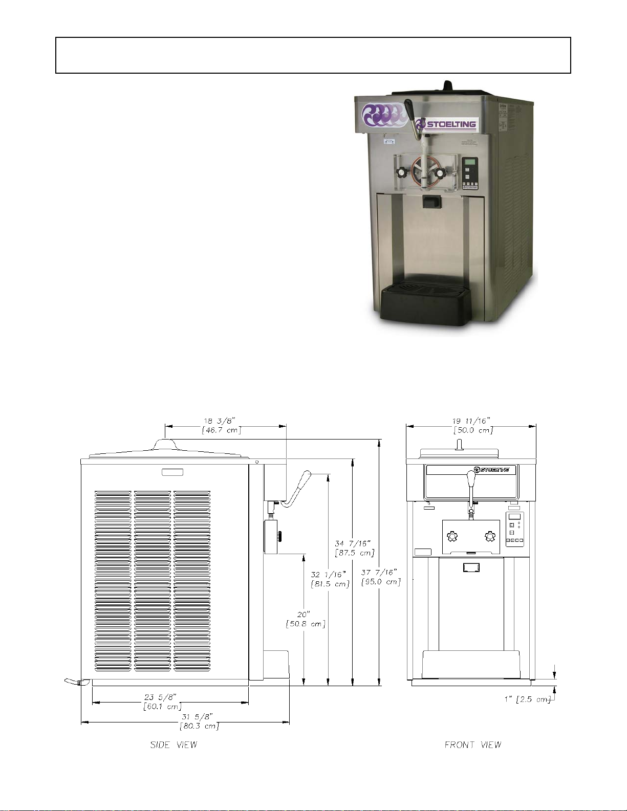
Figure 2-2 Space and Ventilation Requirements
115V
20Amp
Figure 2-3 Electrical Plug
208/230V
20Amp

5
3.1 OPERATOR’S SAFETY PRECAUTIONS
SAFE OPERATION IS NO ACCIDENT; observe these
rules:
A. Know the freezer. Read and understand the
OperatingInstructions.
B. Notice all warning labels on the freezer.
C. Wearproperclothing.Avoidloosefittinggarments,
andremovewatches,ringsorjewelrywhichcould
cause a serious accident.
D. Maintain a clean work area. Avoid accidents by
cleaning up the area and keeping it clean.
E. Stay alert at all times. Know which switch, push
button or control you are about to use and what
effect it is going to have.
F. Disconnectelectricalcordformaintenance.Never
attempt to repair or perform maintenance on the
freezer until the main electrical power has been
disconnected.
G. Donotoperateunderunsafeoperatingconditions.
Neveroperatethefreezerifunusualorexcessive
noise or vibration occurs.
3.2 OPERATING CONTROLS AND INDICATORS
Beforeoperatingthefreezer,itisrequiredthattheoperator
know the function of each operating control. Refer to
Figure3-1for the location of theoperatingcontrolsonthe
freezer.
WARNING
High voltage will shock, burn or cause death. The
OFF-ONswitch mustbe placed in the OFF position
prior to disassembling for cleaning or servicing. Do
not operate machine with cabinet panels removed.
SECTION 3
INITIAL SETUP AND OPERATION
Dispense Rate Adjustor
Main Power OFF-ON
IntelliTec Control
(See Figure 3-2)
Figure 3-1 Freezer Controls

6
A. Spigot Switch
The spigot switch will automatically actuate the
auger drive and refrigeration systems when the
spigot is opened to dispense product. When the
spigotis closed, thedrive motorand compressor
will remain “on” until the product in the barrel
reaches the proper consistency.
B. Main Freezer Power OFF-ON Switch
TheMainFreezerPowerOFF-ONswitchisatwo
positiontoggleswitchusedtosupplypowertothe
control circuit. When the switch is in the OFF
position, power will not be supplied to the control
boardorrefrigerationsystem.Whentheswitchis
in the ON position, the freezer will operate in the
freezingmode orcleaningmode.Thefreezerwill
be in the sleep mode until a switch is activated.
C. PUSH TO FREEZE Button
The PUSH TO FREEZE button is used to initiate
the serve mode. To start the freezer, place the
Main Freezer Power OFF-ON switch in the ON
positionandpressthePUSHTOFREEZEbutton.
NOTE
After the drive motor starts, there is a 3 second de-
lay before the compressor starts.
D. LEDs
Themembraneswitchfeaturestwolights;agreen
LED and an amber LED. The green LED is lit
duringservemode.Duringfreezedown,thegreen
LED is not lit. When product consistency
approaches 75% in the freezing cylinder, the
greenLEDflashes.TheamberLEDislitduringall
othermodes. In theevent of anerror or whenthe
freezingcylinderisoff,bothLEDswillalternatively
flash. NOTE
If the freezer shuts off, and alternating green and
amber lights are flashing, the freezer is in an error
condition.Ifthe LCD displaysanerror,turn the Main
Freezer Power OFF-ON switch to the OFF posi-
tion, correct the problem (Refer to Troubleshooting
in Section 4) and turn the freezer back on.
E. CLEAN Button
The CLEAN button will stop all refrigeration and
startaugerrotation.ACLEANmessagewilldisplay
on the LCD screen and a 5 minute timer begins.
To exit the CLEAN mode, press the CLEAN
button again. If the freezer is left in CLEAN for
more than 20 minutes, it will go into an error to
prevent damage to the freezing cylinder. When
thiserroroccurs,refrigerationwillstarttoprevent
mix spoilage. To reset, place the Main Freezer
Power OFF-ON switch in the OFF position and
back in the ON position.
F. Mix Low Light Indicator
The MIX LOW message will appear on the LCD
displaytoalerttheoperatortoalowmixcondition.
The message will display when there is
approximatelyonegallonofmixleftinthehopper.
When the MIX LOW message is displayed, refill
hopperimmediately.
NOTE
Failure to refill hopper immediately may result in
operationalproblems.
G. DISPENSE RATE ADJUSTERS
The dispense rate adjuster limits the opening of
the spigot. To adjust product dispense rate, turn
the adjusting knob clockwise for slower flow and
counterclockwise for faster flow. It takes at least
fivecompleteturnsoftheadjustingknobtomake
a noticeable difference in the dispense rate.
H. FRONT DOOR SAFETY SWITCH
The front door safety switch prevents the auger
fromturningwhenthe front door is removed. The
switch is open when the door is not in place and
closed when the door is properly installed.
I. MENU NAVIGATION BUTTONS

7
The Menu Navigation Buttons allow the user to
displayinformationregardingthefreezer'sstatus
ofoperationaswellasadjustproductconsistency.
Selection Button (SEL) The SEL button is not
functional in the normal operation mode. This
button is only used by service technicians for
freezercalibration.
SetButton(SET)Pressingthisbuttonwillsavea
changemadeto the productconsistency setting.
RefertoSection3-15forconsistencyadjustment
procedures.
Left Arrow Button (Õ) Pressing any button on
the control panel will automatically illuminate the
display.Thebacklightwillturnoffseveralseconds
afteruse.Tokeepthedisplayconstantlylit,press
and hold the left (Õ) button for five seconds. The
backlightfunctioncanberesettonormaloperation
in the same manner.
Up Arrow Button (×) Pressing this button will
change the value of the product consistency.
RefertoSection3-15forconsistencyadjustment
procedures.
3.3 SANITIZING
Sanitizing must be done after the freezer is cleaned and
justbeforethehopperisfilledwithmix.Sanitizingthenight
beforeisnoteffective.However,youshouldalwaysclean
the freezer and parts after each use.
THE UNITED STATES DEPARTMENT OF AGRI-
CULTURE AND THE FOOD AND DRUG ADMIN-
ISTRATIONREQUIRETHATALLCLEANINGAND
SANITIZING SOLUTIONS USED WITH FOOD
PROCESSINGEQUIPMENTBECERTIFIEDFOR
THIS USE.
Whensanitizingthefreezer,refertolocalsanitaryregula-
tions for applicable codes and recommended sanitizing
products and procedures. The frequency of sanitizing
must comply with local health regulations.
Mix sanitizer according to manufacturer’s instructions to
provide a 100 parts per million strength solution. Mix
sanitizer in quantities of no less than 2 gallons (7.5 liters)
of 90° to 110°F (32° to 43°C) water. Allow sanitizer to
contact the surfaces to be sanitized for 5 minutes. Any
sanitizer must be used only in accordance with the
manufacturer’s instructions.
In general, sanitizing may be conducted as follows:
A. Prepare Stera-Sheen Green Label Sanitizer or
equivalent according to manufacturer’s
instructionstoprovidea100ppmstrengthsolution.
Mix the sanitizer in quantities of no less than 2
gallons of 90° to 110°F (32° to 43°C) water. Any
sanitizer must be used only in accordance with
the manufacturer’s instructions.
B. Push the mix inlet regulator into hopper with air
inlet (long) tube toward the front of the freezer
(Fig. 3-3).
C. Place the Main Freezer Power OFF-ON toggle
switch in the ON position and press the CLEAN
switch. Check for leaks.
Figure 3-2 IntelliTec Control
Push to Freeze
Green Light
Amber Light
SEL Button
SET Button
Clean Switch
Up Arrow Button
Left Arrow Button
Figure 3-3 Mix Inlet Regulator
CAUTION
Donotallowsanitizertoremain in contactwith stain-
less steel freezer parts for prolonged periods. Pro-
longed contact of sanitizer with freezer may cause
corrosion of stainless steel parts.

8
D. Clean sides of hopper, mix inlet regulator and
underside of hopper cover using a sanitized soft
bristlebrushdippedinthesanitizingsolution.(Fig.
3-4).
E. Afterfiveminutes,placeabucketunderthespigot
andopenspigottodrainsanitizingsolution.When
solution has drained, press the CLEAN button to
stop the auger. Allow the freezer barrel to drain
completely.
3.4 FREEZE DOWN AND OPERATION
This section covers the recommended operating proce-
dures to be followed for the safe operation of the freezer.
A. Sanitize just prior to use.
B. PlacetheMainFreezerPowerOFF-ONswitchin
the OFF position.
NOTE
Make sure the mix inlet regulator is in place before
adding mix.
C. With spigot open, pour approximately 1 gallon
(3.8 liters) of fully thawed mix into the hopper.
Allow the mix to flush out about 8 ounces (0.23
liters) of sanitizing solution and liquid mix. Close
the spigot.
D. Fill hopper with approximately 3 gallons (11.4
liters) of pre-chilled (40°F or 4°C) mix.
NOTE
Do not overfill the hopper. Mix level must not be
higherthan theair inlettube onthe mixinlet regula-
tor.
E. The freezer barrel will automatically fill until it is
about 1/2 full. If freezer barrel does not fill, check
forobstructioninthemixinletregulator.Iffreezer
barrel fills over 1/2 full, indicated by low overrun,
checkfor leaks at the mix inlet regulatoro-ring or
check if the mix inlet regulator was installed
correctly or that the freezer is level.
F. PlacetheMainFreezerPowerOFF-ONswitchin
theONposition,thenpressthePUSHTOFREEZE
switch. NOTE
After the drive motor starts, there is a 3 second de-
lay before the compressor starts.
G. After about 6 to 10 minutes the product will be at
consistency and the LCD screen will display
"SERVE". The product is ready to serve. Freeze
down time may be longer for some frozen diet
dessert mixes. High ambient temperatures may
extend freeze down time.
H. For normal dispensing, pull the spigot handle
down to fully open the spigot.
NOTE
Refrigeration is automatically activated when the
spigot is opened. Close the spigot completely after
dispensing.
I. Thefreezerisdesignedtodispensetheproductat
areasonabledrawrate.Ifthefreezerisoverdrawn,
theresultisasoftproductoraproductthatwillnot
dispense at all. If this should occur, wait until the
barsfillthelowersectionof the display (Fig.3-5).
Figure 3-4 Sanitizing Hopper
Figure 3-5 During Freezing Cycle

9
J. Do not operate the freezer when the MIX LOW
light is on or with less than 1-3/4 inches (4.4 cm)
ofmixinthehopper.Refillthehopperimmediately.
NOTE
The freezer has standby and sleep modes. When
the freezer is not used, after a preset number of
freezing cycles, it will enter the standby mode (fol-
lowedby sleep mode)and remainthere untilsome-
one draws a product or presses the PUSH TO
FREEZE button. In the sleep mode, the freezer will
keep the product below 41°F (5°C). Sleep modes
are not to be used in place of cleaning and sanitiz-
ing. Frequency of cleaning and sanitizing is deter-
minedby Federal, State, and localregulatory agen-
cies.
3.5 MIX INFORMATION
Mix can vary considerably from one manufacturer to
another. Differences in the amount of butterfat content
andquantity andqualityofotheringredientshavea direct
bearingonthefinishedfrozenproduct.Achangeinfreezer
performance that cannot be explained by a technical
problem may be related to the mix.
Proper product serving temperature varies from one
manufacturer’smixtoanother.Softservemixesgenerally
providesatisfactoryproductfrom18°to20°F(-7°to-6°C),
shake mixes 24° to 28°F (-4° to -2°C).
When checking the temperature, stir the thermometer in
the frozen product to read the true temperature.
Old mix or mix that has been stored at elevated tempera-
tureswillproducepoor-qualityproductwithabadtasteand
unacceptable appearance. To retard bacteria growth in
dairybasedmixes, the beststoragetemperaturerangeis
between 36° to 40°F (2.2° to 4.4°C).
Some products tend to foam more than others. If foam
appearsinthehopper,skimoffwithasanitizedutensiland
discard. Periodically, stir the mix in the hopper with a
sanitized utensil to help prevent excess foam.
3.6 REMOVING MIX FROM FREEZER
To remove the mix from the freezer, refer to the following
steps:
A. Removethemixinletregulatorfromthehopperby
pulling straight up.
B. PresstheCLEANbuttontorotatetheauger.Allow
themixtoagitateinfreezerbarreluntilthemixhas
become a liquid, about 5 minutes.
C. Drain the liquid mix by opening the spigot. A
bucket or container should be placed under the
spigot to catch the liquid mix.
D. PlacetheMainFreezerPowerOFF-ONswitchin
the OFF position.
3.7 CLEANING THE FREEZER
NOTE
The frequency of cleaning the freezer and freezer
parts must comply with local health regulations.
After the mix has been removed from the freezer, the
freezermustbecleaned.Tocleanthefreezer,refertothe
following steps:
A. Fill the hopper with 2 gallons (7.5 liters) of tap
water.
B. PlacetheMainFreezerPowerOFF-ONswitchin
theONpositionandpresstheCLEANswitch.The
auger will start to rotate.
C. Allow the water to agitate for approximately 30
seconds. NOTE
Iffreezer is leftinCLEAN for morethan 20minutes,
the display will show an error code. To reset, place
theMainFreezer PowerOFF-ONswitch intheOFF
position and back in the ON position.
D. Openthespigotto drain the water. Remember to
place a container under the spigot to catch the
water. When the water has drained, place the
switch in the OFF position. Allow the freezing
cylinder to drain completely.
E. Prepare detergent water by mixing 2 oz. of
Palmolive detergent or equivalent in 2 gallons of
90°to110°F (32° to43°C)water.RepeatstepsA
through D using the detergent solution.
3.8 DISASSEMBLY OF FREEZER PARTS
CAUTION
Hazardous Moving Parts
Revolving auger shaft can grab and cause injury.
Place the Main Freezer Power OFF-ON switch in
theOFF position before disassembling forcleaning
or servicing.
Inspectionforworn or brokenparts should bemadeeach
timethefreezerisdisassembled.Allwornorbrokenparts
should be replaced to ensure safety to both the operator
and the customer and to maintain good freezer perfor-
mance and a quality product. Check the wear line on the
auger flights on a regular basis (Fig. 3-6) and replace as
needed.Frequencyofcleaningmustcomplywiththelocal
healthregulations.

10
To disassemble the freezer, refer to the following steps:
A. Remove hopper cover and drain tray.
B. Removethemixinletregulatorfromthehopperby
pulling straight up.
C. Remove the front door by turning the circular
knobsandthenpullingthefrontdooroffthestuds.
D. Removetherosettecapfromthefrontdoor.Push
the spigot body through the bottom of the front
door and remove.
E. Removethefrontaugersupportandbushing(Fig.
3-7).
F. Remove the auger assembly from the freezer
(Fig. 3-8). Pull the auger out of the freezer barrel
slowly.As theauger is being pulled out,carefully
remove each of the plastic flights with springs.
G. Keepthe rear ofthe augershaft tipped uponce it
isclearofthefreezertoavoid dropping rear seal.
H. Remove the rear seal.
I. Wipesocketlubricantfrom the drive end (rear) of
the auger with a cloth or paper towel.
J. Remove all o-rings from parts by first wiping off
the lubricant using a clean paper towel. Then
squeezetheo-ringupwardwithadrycloth(Fig.3-
8). When a loop is formed, roll out of the o-ring
groove.
CAUTION
Do not use any type of sharp object to remove the
o-rings.
3.9 CLEANING THE FREEZER PARTS
Place all loose parts in a pan or container and take to the
wash sink for cleaning. To clean freezer parts refer to the
following steps:
Figure 3-6 Auger Flight Wear
Figure 3-7 Removing Auger Support
Figure 3-8 Removing Auger Shaft and Flights
Figure 3-9 Removing O-Ring
Wear Line

11
A. Prepare detergent water by mixing 2 oz. of
Palmolive detergent or equivalent in 2 gallons of
90° to 110°F (32° to 43°C) water. Place all parts
in detergent solution and clean with provided
brushes. Rinse all parts with clean 90° to 110°F
(32° to 43°C) water.
B. Wash the hopper and freezing cylinder with the
90° to 110°F (32° to 43°C) detergent water and
brushes provided (Refer to Figure 3-9).
C. Cleantherearsealsurfacesfromtheinsideofthe
freezing cylinder with the 90° to 110°F (32° to
43°C) detergent water.
D. Cleanthedriptrayandinsertwithasoapsolution.
Rinse with clean hot water.
3.10 SANITIZE FREEZER AND FREEZER
PARTS
A. Use a sanitizing solution mixed according to
manufacturer's instructions to provide 100 parts
per million strength solution. Mix sanitizer in
quantities of no less than 2 gallons (7.5 liters) of
120°F water. Allow the sanitizer to contact the
surfacestobesanitizedfor5minutes.Anysanitizer
must be used only in accordance with the
manufacturer's instructions.
B. Place all parts in the sanitizing solution, then
remove and let air dry.
C. Usingthis sanitizingsolution andthe largebarrel
brush provided, sanitize the rear of the barrel by
dipping the brush in the sanitizing solution and
brushing the rear of the barrel.
3.11 ASSEMBLY OF FREEZER
Toassemblethefreezerparts,refertothefollowingsteps:
NOTE
Petrol Gel sanitary lubricant or equivalent must be
used when lubrication of parts is specified.
NOTE
The United States Department of Agriculture and
the Food and Drug Administration require that lu-
bricantsused on foodprocessingequipmentbe cer-
tifiedfor this use.Use lubricantsonly inaccordance
with the manufacturer’s instructions.
A. Assemble all o-rings onto parts dry, without
lubrication. Then apply a thin film of sanitary
lubrication to exposed surfaces of the o-rings.
Applyathinfilmofsanitarylubricanttometalpart
of rear seal. Also apply a thin film of sanitary
lubricant inside and outside of the front auger
support bushing.
B. Assemble the rear seal onto the auger with the
largeendtotherear.Besuretheo-ringisinplace
before installing the rear seal.
C. Lubricate the auger drive (rear) with a small
amountofwhitesocketlubricant.Asmallcontainer
of socket lubricant is shipped with the freezer.
D. Screwthespringsontothestudsinplasticflights.
Springsmustbescrewedintotheflightscompletely
to provide proper compression (Fig. 3-10).
CAUTION
Do not place the mix inlet regulator into the hopper
before installing the auger.Attempting to install the
auger with the mix inlet regulator in place will dam-
age the mix inlet regulator.
E. Installthetwoplasticflightsontorearoftheauger
and insert part way into freezer barrel.
F. Installtheremainingplasticflights,pushtheauger
into the freezer barrel and rotate slowly until the
auger engages the drive shaft.
G. Installthebushingandaugersupportintothefront
of the auger with one leg of the support pointing
straight up.
Figure 3-10 Cleaning Freezer Barrel
Figure 3-11 Auger Springs

12
H. Install the spigot body with o-ring into the front
door from bottom (Fig. 3-11). Push straight up
until the spigot is in place.
I. Install the front door on the freezer.
J. Install the circular knobs on the freezer studs.
CAUTION
Overtightening or uneven tensioning of circular
knobs may cause damage to front door and cause
leaking. Hand tighten circular knobs evenly.
K. Look for the proper seal between the freezer
barrel, o-ring, and front door.
L. Install the mix inlet regulator into the freezer with
the air tube to the front of the freezer.
M. Install hopper cover and drain tray.
3.12 ROUTINE CLEANING
To remove spilled or dried mix from the freezer exterior,
simplywash in thedirection ofthe finish withwarm soapy
water and wipe dry. Do not use highly abrasive materials
as they will mar the finish.
3.13 PREVENTIVE MAINTENANCE
It is recommended that a maintenance schedule be fol-
lowed to keep the freezer clean and operating properly.
Cleaning and Sanitizing Information
Soft serve freezers require special consideration when it
comes to food safety and proper cleaning and sanitizing.
The following information has been compiled by Purdy
ProductsCompany,makers ofStera-SheenGreenLabel
Cleaner/Sanitizerandspecificallycoversissuesforclean-
ingandsanitizingfrozendessertmachines.Thisinforma-
tionismeant to supplementacomprehensivefoodsafety
program.
Soil Materials Associated with Frozen Dessert
Machines
MILKFAT/BUTTERFAT – As components of ice-cream/
frozen custard mix, these soils will accumulate on the
interior surfaces of the machine and its parts. Fats are
difficulttoremoveand help attributetomilkstonebuildup.
MILKSTONE – Is a white/gray film that forms on equip-
mentandutensilsthatcomeincontactwithdairyproducts.
Thesefilmswillaccumulateslowlyonsurfacesbecauseof
ineffectivecleaning,useof hard water,orboth.Milkstone
is usually a porous deposit, which will harbor microbial
contaminants and eventually defy sanitizing efforts.
Once milkstone has formed, it is very difficult to remove.
Without using the correct product and procedure, it is
nearly impossible to remove a thick layer of milkstone.
(NOTE: general-purpose cleaners DO NOT remove
milkstone.) This can lead to high bacteria counts and a
food safety dilemma.
IT IS BEST TO CONTROL MILKSTONE ON A DAILY
BASISBEFOREITCANBECOMEASIGNIFICANTFOOD
SAFETY PROBLEM.
Inadditiontofoodsafety,milkstonecancausepremature
weartomachinepartswhichcanaddtocostsforreplace-
ment parts or possibly more expensive repairs if worn
machine parts are not replaced once they have become
excessivelyworn.
Important Differences Between Cleaning and
Sanitizing
CLEANING vs. SANITIZING
Itisimportanttodistinguishbetweencleaningandsanitiz-
ing. Although these terms may sound synonymous, they
are not. BOTH are required for adequate food safety and
proper machine maintenance.
CLEANING
• Is the removal of soil materials from a surface.
• Is a prerequisite for effective sanitizing.
NOTE
An UNCLEAN surface will harbor bacteria that can
defy sanitizing efforts.
Bacteria can develop and resist sanitizing efforts within a
layer of soil material (milkstone). Thorough cleaning pro-
cedures that involve milkstone removal are critical for
operators of frozen dessert machines.
SANITIZING
• Kills bacteria.
• Can be effective on clean surfaces only.
Figure 3-11 Front Door Parts

13
NOTE
Using a SANITIZER on an unclean surface will not
guaranteeacleanandsafefrozen dessert machine.
Proper Daily Maintenance: The Only Way to Assure
Food Safety and Product Quality
Proper daily maintenance can involve a wide variety of
products and procedures. Overall, the products and pro-
cedures fall into three separate categories. (Please note
that this is a brief overview intended for informational
purposesonly.)
1. CLEANING–Thisinvolvesdrainingmixfromthe
freezerbarrelandrinsingthemachinewithwater.
Next,acleanerisrunthroughthemachine.Then,
the machine is disassembled and removable
parts are taken to the sink for cleaning.
2. MILKSTONE REMOVAL – Since almost all
cleaners do not have the ability to remove
milkstone, the use of a delimer becomes
necessary. Although this procedure may not be
needed on a daily basis, it will usually follow the
cleaning procedure. It requires letting a delimer
solution soak in the machine for an extended
periodoftime.Individualpartsarealsosoakedin
adelimingsolutionforanextendedperiodoftime
(more about delimers in Additional Information).
3. SANITIZING–Afterthemachinehasbeencleaned
and contains no milkstone, the machine is
reassembled. Then a FDA-approved sanitizing
solutionisrunthroughthemachinetokillbacteria.
The machine is then ready for food preparation.
As a recommended cleaner and sanitizer for your frozen
dessertmachine,STERA-SHEENhasproventobeoneof
the best daily maintenance products for:
• CLEANING – Thorough removal of all solids
including butterfat and milk fat.
• MILKSTONE REMOVAL – Complete removal of
milkstone.
• SANITIZING – FDA-approved no rinse sanitizer
for food contact surfaces.
AdditionalInformation
THE USE OF DELIMERS
A delimer is a strong acid that has the ability to dissolve
milkstone. This type of chemical may become necessary
once high levels of milkstone have developed. While
these products are very effective for removing HIGH
levels of milkstone, they are not ideal for two reasons:
1. PRODUCTSAFETY–Strongacidsaredangerous
chemicals and handling them requires safety
2. MACHINE DAMAGE – Strong acids will attack
metal and rubber causing premature wear of
parts. The use of a delimer needs to be closely
monitored to avoid damage to machine surfaces
and parts.
WithproperdailyuseofSTERA-SHEENoritsequivalent,
there is no need for the use of a DELIMER.
DO NOT USE BLEACH
• BLEACH HAS ABSOLUTELY NO CLEANING
PROPERTIES.
• BLEACHISCORROSIVE.Itcanandwilldamage
componentsofthemachinecausingprematurewearand
metal corrosion.
GENERAL PURPOSE CLEANERS
General purpose cleaners do not have the ability to re-
move milkstone. Milkstone will become a problem if not
remedied with additional products and procedures.
THE USE OF CHLORINE TEST STRIPS
“Test strips” are used to determine concentrations of
active chlorine in sanitizing solutions. To use the strips,
tearoff a smallportion and submergeit intothesanitizing
solution.Then,comparethecolorchangetothecolorkey
on the side of the test strip dispenser to determine the
approximate chlorine concentration.
The ideal concentration of chlorine needs to be 100 ppm
(as stated by the FDA). NOTE
Followthedirectionsonthecontainerforpropercon-
centration.
There are two main factors that contribute to falling chlo-
rine concentrations in a sanitizing solution.
1. PRODUCT USE – As the chlorine in the solution
is being used, chlorine concentrations fall.
2. TIME–Astimepasses,smallamountsofchlorine
“evaporate” from the solution. (That is why you
can smell it.)
Sanitizingsolutionsshouldnotbeallowedtofallbelow100
ppm chlorine. New solutions should be mixed once old
solutions become ineffective
B. DAILY
1. The exterior should be kept clean at all times to
preserve the luster of the stainless steel. A mild
alkalinecleanerisrecommended.Useasoftcloth
or sponge to apply the cleaner.
CAUTION
Do not use acidic cleansers, strong caustic com-
pounds or abrasive materials to clean any part of
the freezer exterior or plastic parts. Use of these
types of cleaners will cause equipment damage.
C. WEEKLY
1. Check o-rings and rear seal for excessive wear
and replace if necessary.

14
2. Remove the drip tray by gently lifting up to
disengagefromthesupportandpullingout.Clean
behindthedriptrayand front of the freezer with a
soap solution.
D. QUARTERLY
WARNING
High voltage will shock, burn or cause death. Turn
off and lock out main power disconnect before ser-
vicing. Do not operate machine with panels re-
moved.
Theair-cooledcondenserisacoppertubeandaluminum
fin type. Condensing is totally dependent upon airflow. A
pluggedcondenserfilter,condenser,orrestrictionsinthe
louvered panel will restrict airflow. This will lower the
capacity of the system and damage the compressor.
Thecondensermustbekeptcleanofdirtandgrease.The
freezermust havea minimumof 3”(7.5 cm) of ventilation
on the right and left sides of the unit for free flow of air.
Makesurethefreezerisnotpullingover100°F(37°C)air
from other equipment in the area.
Thewater-cooledcondenserisatubeandshelltype.The
condenserneedsacool,cleansupplyofwatertoproperly
coolthefreezer,inletanddischargelinesmustbe3/8”I.D.
minimum.
Thecondenserandcondenserfilterrequireperiodicclean-
ing. To clean, refer to the following procedures.
1. RemovethePhillips headscrew fromthe bottom
of the right side panel, and then slide the panels
down and out.
2. Toremovethecondenserfilter,graspthetopand
pulloff.Visuallyinspectfordirt.Ifthefilterisdirty,
shake or brush excess dirt off the filter and wash
inwarm,soapywater.Oncethefilteriscleanrinse
thoroughly in warm, clear water and shake dry,
taking care not to damage the filter in any way
(Figure 28).
3. Visually inspect the condenser for dirt by shining
alightthroughthecoilfromtheback(inside)ofthe
condenser.
4. Ifthecondenserisdirty,placeawettoweloverthe
front (outside) of the condenser.
5. Using a vacuum, carefully clean the condenser
coil from the inside and outside of the freezer. A
stiff bristled brush may help in releasing debris
from between the condenser coils.
E. SEMI-ANNUALLY
1. Check drive belt for proper tension. Push belt in
with one finger, belt should deflect about 3/8".
2. Lubricate condenser fan motor with S.A.E. 20
weight oil. Three to six drops is required.
CAUTION
Donotover-lubricate;resultingdamagecouldcause
motor failure.
3.14 EXTENDED STORAGE
Refertothefollowingstepsforstorageofthefreezerover
any long period of shutdown time:
A. Turn the Main Freezer Power OFF-ON switch to
the OFF position.
B. Disconnect (unplug) from the electrical supply
source.
C. Cleanthoroughlywithawarmwaterdetergentall
parts that come in contact with the mix. Rinse in
clean water and dry parts. Do not sanitize.
NOTE
Do not let the cleaning solution stand in the hopper
or in the freezer barrel during the shutdown period.
D. Remove, disassemble and clean the front door,
mix inlet regulator and auger parts. Place the
augerflightsandthefrontauger support bushing
inaplasticbagwithamoistpapertoweltoprevent
them from becoming brittle.
E. In a water cooled freezer, disconnect water lines
anddrainwater.Withaflatheadscrewdriver,hold
the water valve open and use compressed air to
clear the lines of any remaining water.
3.15 PRODUCT CONSISTENCY ADJUSTMENT
TheIntelliTeccontrolmonitorstheconsistency(firmness)
of the product (mix) in the freezing cylinder by monitoring
thedrive motor amp draw. Whenconsistency isreached,
the drive motor and refrigeration system will shut off. The
controlpanelonthefrontofthefreezerallowstheoperator
toadjustthefreezingcylindertocreatethedesiredproduct
consistency.
A. PlacetheFREEZINGCYLINDEROFF/ONswitch
in the ON position.
B. PresstheSETbutton on theControlPanel once.
Fine Adj will appear on the LCD screen (Fig. 3-
12).
This manual suits for next models
1
Table of contents
Other Vollrath Freezer manuals

Vollrath
Vollrath Stoelting E157 User manual

Vollrath
Vollrath Stoelting Endura 111 User manual

Vollrath
Vollrath CBB116 User manual

Vollrath
Vollrath STOELTING O431RC User manual

Vollrath
Vollrath Stoelting SU444 User manual

Vollrath
Vollrath STOELTING Flavor Burst STL-80BLD-DLX User manual

Vollrath
Vollrath Stoelting 100C User manual

Vollrath
Vollrath STOELTING O112 User manual

Vollrath
Vollrath STOELTING SU444-I2 Series User manual

Vollrath
Vollrath STOELTING CF101 User manual