3
2.1 SAFETY PRECAUTIONS
Do not attempt to operate the machine until the safety
precautions and operating instructions in this manual are
read completely and are thoroughly understood.
Take notice of all warning labels on the machine. The
labelshavebeenputtheretohelpmaintainasafeworking
environment.Thelabelshavebeendesignedtowithstand
washing and cleaning. All labels must remain legible for
thelifeofthemachine.Labelsshouldbecheckedperiodi-
callytobesuretheycanberecognizedaswarninglabels.
If danger, warning or caution labels are needed, indicate
the part number, type of label, location of label, and
quantity required along with your address and mail to:
STOELTING, INC.
ATTENTION: Customer Service
502 Hwy. 67
Kiel, Wisconsin 53042
2.2 SHIPMENT AND TRANSIT
The machine has been assembled, operated and in-
spectedatthefactory.Uponarrivalatthefinaldestination,
the entire machine must be checked for any damage
which may have occurred during transit.
With the method of packaging used, the machine should
arriveinexcellentcondition.THECARRIERISRESPON-
SIBLE FOR ALL DAMAGE IN TRANSIT, WHETHER
VISIBLEORCONCEALED.Donotpaythefreightbilluntil
the machine has been checked for damage. Have the
carrier note any visible damage on the freight bill. If
concealeddamageand/orshortage isfoundlater,advise
the carrier within 10 days and request inspection. The
customer must place a claim for damages and/or short-
ages in shipment with the carrier. Stoelting, Inc. cannot
make any claims against the carrier.
2.3 MACHINE INSTALLATION
WARNING
Installation must be completed by a qualified
electrician/refrigeration specialist.
Incorrect installation may cause personal injury,
severedamage tothe machineand will voidfactory
warranty.
Installation of the machine involves moving the machine
close to its permanent location, removing all crating,
setting in place, assembling parts, and cleaning.
A. Uncrate the machine.
SECTION 2
INSTALLATION INSTRUCTIONS
B. Installthefourcasters.Turnthethreadedendinto
the machine until no threads are showing. To
level,turnoutcastersnomorethan1/4"maximum,
then tighten all jam nuts.
C. The machine must be placed in a solid level
position. NOTE
Accurate leveling is necessary for correct drainage
of freezing cylinder and to insure correct overrun.
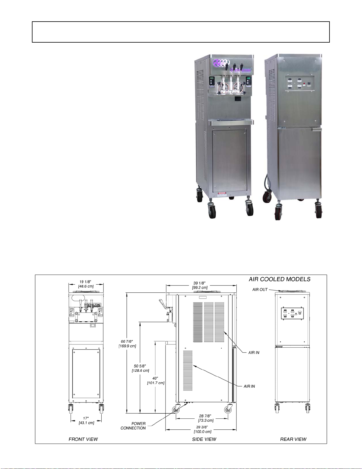
D. Machines with air-cooled condensers require 3"
(7,6 cm) air space on both sides and back for
proper circulation. (Fig. 2-1)
E. Machines that have a water-cooled condenser
require 1/2" NPT supply and drain fittings.
F. Inair-cooledmachines,useavoltmetertomeasure
incoming voltage. If the supply voltage is 215 or
less, then the buck-boost transformer must be
connected to the fan motor. Refer to the wiring
diagram located behind the header panel to
connect. NOTE
Supply voltage must be checked to make sure the
fan motor operates properly.
2.4 INSTALLING PERMANENT WIRING
If permanent wiring is required by local codes, the follow-
ing procedure must be performed:
A. Refer to the nameplate on the side panel of the
machineforspecificelectricalrequirements.Make
surethepowersourceinthebuildingmatchesthe
nameplate requirements.
B. Remove the back panel and the junction box
cover located at the bottom of the machine.
C. Install permanent wiring according to local code.
Figure 2-1 Space and Ventilation Requirements