Vollrath Cayenne Series User manual

Item No. 17030-1 ml Rev 09/14
ENGLISH
Operator’s Manual
English, Spanish, French
CAYENNE®HEAT AND LIGHT STRIPS
Thank you for purchasing this Vollrath Food Processing Equipment. Before operating the equipment, read and familiarize yourself with
the following operating and safety instructions. SAVE THESE INSTRUCTIONS FOR FUTURE REFERENCE. Save the original box and
packaging. Use this packaging to ship the equipment if repairs are needed.
RegisteR youR pRoduct on-line at www.vollRath.com

OperatOr’sManual
2
ENGLISH
unit installation cleaRances
safety pRecautions
To ensure safe operation, read the following statements and understand
their meaning. This manual contains safety precautions which are
explained below. Please read carefully.
WARNING
Warning is used to indicate the presence of a hazard that can cause
severe personal injury, death, or substantial property damage if the
warning is ignored.
CAUTION
Caution is used to indicate the presence of a hazard that will or can
cause minor personal injury or property damage if the caution is
ignored.
NOTE
Note is used to notify people of installation, operation, or maintenance
information that is important but not hazard-related.
For Your Safety!
These precautions should be followed at all times. Failure to follow
these precautions could result in injury to yourself and others or damage
the equipment.
To reduce risk of injury or damage to the unit:
Use only grounded electrical outlets or circuits matching the nameplate
rated voltage.
Unit should only be used in a at, level position.
Turn off unit and let it cool before cleaning or moving.
Do not operate unattended.
Do not use extension cords, power strips or surge protectors with this
unit.
Install with distances specied in the Unit Installation section of this
manual. Minimum distance to the following surfaces.
Combustible surroundings 5” Sides 2” Top
Non Combustible surroundings 1” Sides 1” Top
Setback from edge of pass-through 8” from any edge
Units that require wiring for installation must follow National Electrical
Code (NEC) standards and local ordinances.
Only use coated light bulbs that meet NSF standards and are
specically designed for foodservice areas. Breakage of bulbs that are
not coated could cause injury or contaminate food.
Do not place materials on or allow combustible materials to come in
contact with unit.
There are no serviceable parts in this unit. Contact a Vollrath
Authorized Service Agent for service.
Authorized service agent must use genuine Vollrath replacement parts.
Failure to do so will void warranty and may cause a safety hazard.
Do not spray controls or outside of unit with liquids or cleaning agents.
Units that require a circuit breaker larger than 20 amps must have
separate circuit for the lighting circuit that is less than 20 amps.
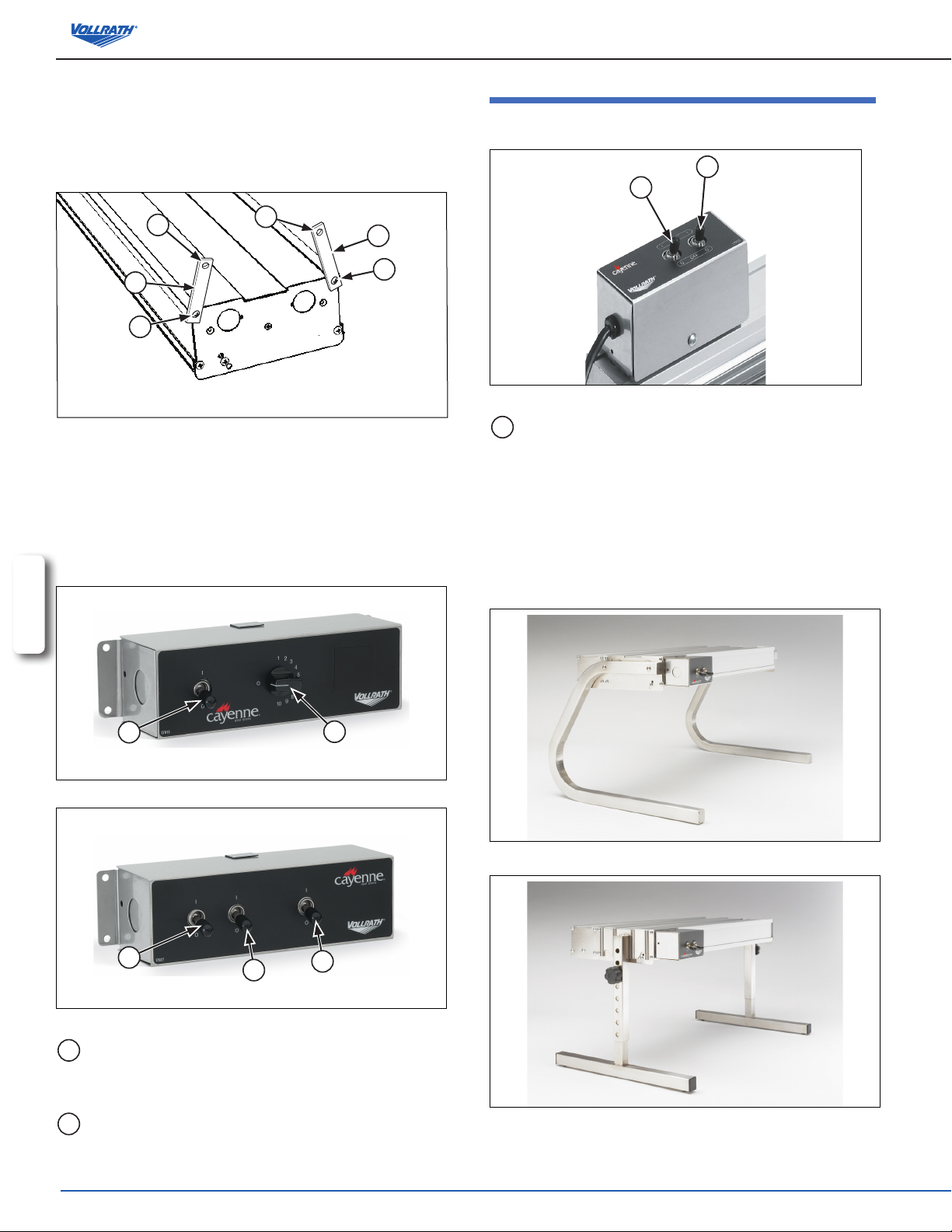
function and puRpose
Heat Strips = These units are intended to be used as a heat source to help
maintain food at safe temperatures until served. They are not intended
or designed to cook raw food or to reheat prepared food. Food must be
prepared and placed in food stations at proper temperatures.
Light Strips = These units are intended to illuminate food serving display
areas or food preparation areas.
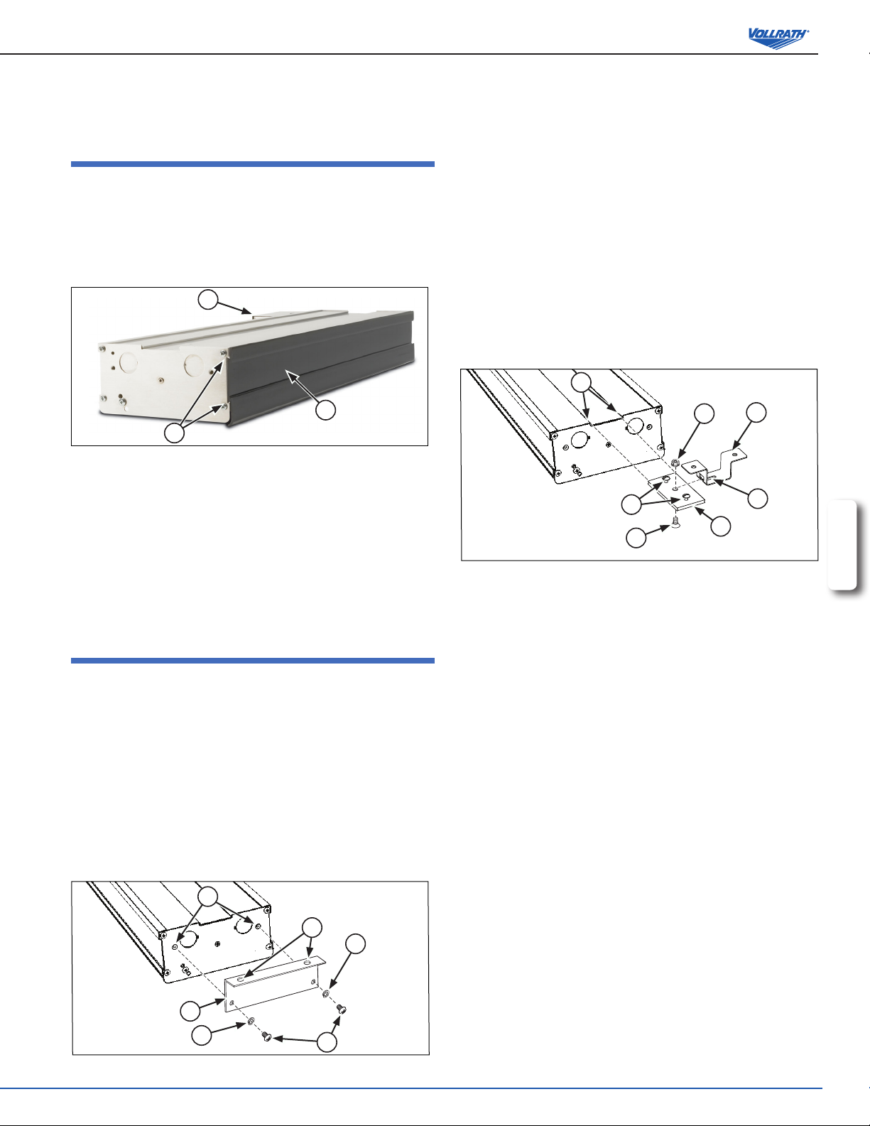
unpacking the equipment and initial setup
Carefully remove crating or packaging materials from the unit. Dispose of all
packaging ,materials in an environmentally responsible manner.
WARNING
Fire Hazard.
Do not install unit near combustible material. Do not
place combustible material under or on top of unit.
Discoloration or combustion could occur.
WARNING
Electrical Shock Hazard.
Keep water and other liquids from entering the
inside of the unit. Liquid inside the unit could cause
an electrical shock. Unit must be installed by
qualied personal in accordance with all local and
national ordinances. Do not use a power cord that
has been modied or damaged.
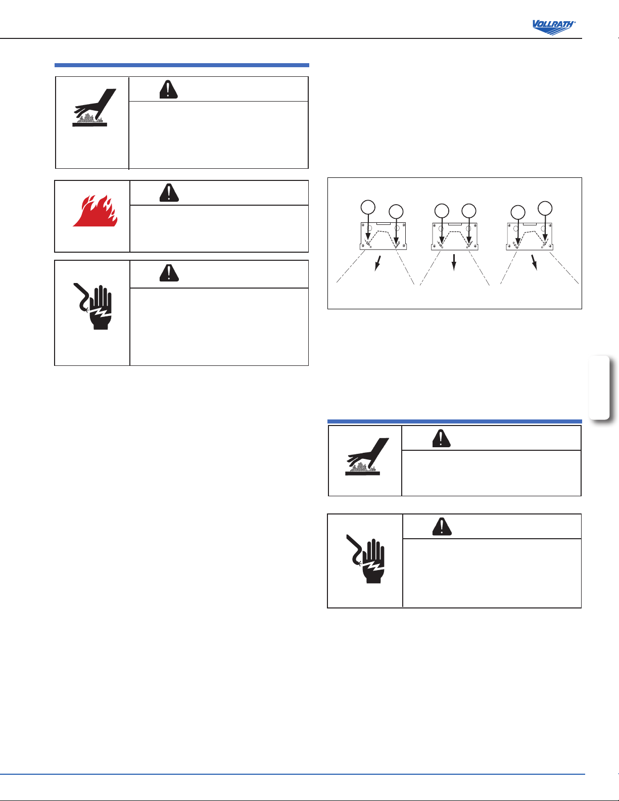
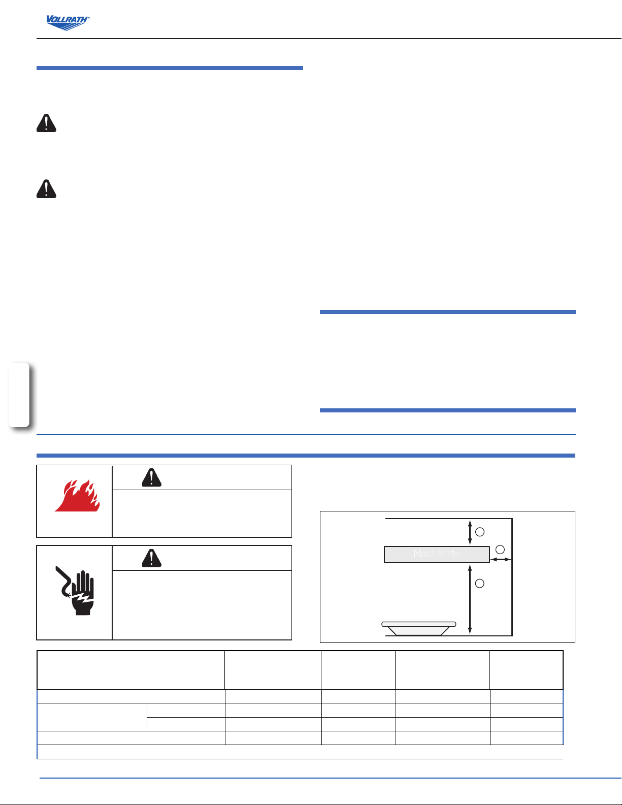
This unit must be installed by qualied personal in compliance with electrical
codes. The following distances must be kept between the unit and the
surrounding surfaces for safe operation. It is recommended that two (2) or
more people assist with the installation of this unit.
A
B
C
Heat Strip
Minimum Clearances
Single
Non-Combustible
Surface
Single
Combustible
Surface
Dual
Non-Combustible
Surface
Dual
Combustible
Surface
ATop of strip to surface above (minimum) 1" (2.5 cm) 2" (5.1 cm) 1" (2.5 cm) 2" (5.1 cm)
BBottom of strip to surface
below
Medium Wattage 11" (27.9 cm) 13" (33.0 cm) 18" (45.7 cm) 20" (50.8 cm)
High Wattage 16" (40.6 cm) 16" (40.6 cm) 24" (60.9 cm) 25" (63.5 cm)
CSide of strip to adjacent surface (minimum) 1" (2.5 cm) 5" (12.7 cm) 1" (2.5 cm) 5" (12.7 cm)
Setback from front opening on pass through application: maximum of 8" (20.3 cm)

3
ENGLISH
OperatOr’sManual
3. Mount the brackets and unit to a suitable surface using holes (E) and
suitable hardware.
centeR mount installation
Top mount brackets may be purchased as an option for direct-wired units.
The brackets are available in 1” height or 2” height. Dual units require
brackets on each unit.
NOTE:
For units longer than 72”, a minimum of three (3) mounting points
consisting of the two ends and the center of the unit must be used.
1. Access the area the unit will be mounted in and mark the location the
center mount brackets will be mounted. Make sure the material the unit
will be mounted to will support the weight of the unit.
2. The brackets must be located near the ends of the unit for greatest
stability.
3. Mount the hanging bracket (A) with the “T” slot cutout, in the locations
identied in step 1. Figure 3.
D
BG
C
A
F
E
Figure 3. Installing Center Mount Brackets.
4. Loosen the two screws (B) located in the center of the at channel
plates (C) far enough so they do not protrude out of the bottom of the
plate.
5. Slide the channel plates (C) into the channel (D) on the top of the unit.
6. Measure the distance from the center points of the hanging brackets
(A) and slide the channel plates (C) in the channel (D) on the top of the
unit so the center screws (E) in the channel plate (C) match the distance
between the center of the “T” slot (G) in the brackets (A).
7. Tighten the two outside screws (B) in the channel plate (C) to lock the
channel plate in position.
8. Loosen the nut (F) in the center of the channel plate (C) but DO NOT
REMOVE.
9. Raise the unit and align the nut (F) in the center of the channel plate (C)
with the “T” in the bracket (A) mounted in step 2.
10. Slide the nut (F) through the “T” slot and TIGHTEN THE NUT to keep the
unit in place. THE NUT MUST BE TIGHTENED TO PREVENT THE UNIT
FROM SLIPPING OUT OF THE BRACKET.
chain mount installation
NOTE: Units over 72” in length, must use the center mounting point.
1. The unit is shipped with mounting tabs (A) located on each end of
the unit. For units that are longer than 72”, three (3) mounting points
consisting of the two ends and the center of the unit must be used. See
Figure 4.
2. Loosen the screws (B) holding the mounting tabs in place but do not
remove. Rotate tabs (A) to an upright position and the attach chain to
holes (C). The chain must support each side of each end of the unit
evenly.
NOTE:
This unit must be installed in an area that will not be affected by the heat
from the unit. Damage to solid surface counter tops or other materials in
the heat zone of this product are not covered under warranty.
kool-touch®tRim installation
The Kool-Touch®trim option is shipped separately. It will need to be installed
on the unit. We recommend that this option be installed before the unit is
mounted.
1. Beginning on the side that does not have the control box (A), slide the
Kool-Touch®(B) panel into position by starting at one end of the unit. Slide
the Kool-Touch®panel in the channel (C) on the side of the unit until it is in
place. (Ganged units will require two pieces trimmed to t). See Figure 1.
B
A
C
Figure 1. Installation of Kool-Touch®Panels.
2. The side of the unit that has the control box will need to be trimmed.
Measure the area that is to be covered by the Kool-Touch®panel.
3. Mark the length to be covered on the Kool-Touch®panel.
4. Place a damp soft cloth under the end of the Kool-Touch®panel to be cut
to prevent the Kool-Touch®panel from scratching or slipping while it is
being cut.
5. Using a hacksaw with a ne metal or plastic blade, slowly cut the panel to
length.
6. Install the panel on the unit in the same manner as the opposite side.
unit installation - diRect wiRe mounting
top mount installation
Top mount brackets may be purchased as an option for direct-wired units. The
brackets are available in 1” height or 2” height. Dual units require two sets of
brackets.
NOTE:
Top mount brackets may not be used with units longer than 72”.
1. Access the area the unit will be mounted in and mark the location the
center mount brackets will be mounted. Make sure the material the unit
will be mounted to will support the weight of the unit.
2. Secure the top mount bracket (A) to the mounting holes (B) using
lockwashers (C) and screws (D). Repeat on the other end. See Figure 2.
A
B
D
C
C
E
Figure 2. Installing Top Mount Brackets.

OperatOr’sManual
4
ENGLISH
unit installation - coRded mounting
onBoaRd toggle contRols
Figure 7. On Board Toggle Control with Switches
AON/OFF Toggle Switch. Move the toggle switch to the up
position for “ON”. Move the toggle switch to the down position
for “OFF”.
mounting options
NOTE: UL requires all cord and plug heat strips, from all
manufacturers be mounted on legs. All heat strips are custom ordered
and therefore cannot be cancelled or returned per Vollrath Terms and
Conditions.
Figure 8. Stainless Steel C-Leg Stand - 13” (33 cm)
Figure 9. Stainless Steel T-Leg Stand -
Adjustable 8 to 15” (22.8 to 38.1 cm)
3. Hang chain from an appropriate hanging point directly over the area to be
kept warm. Make sure the hanging point is adequate for the total weight of
the unit and chain.
4. Adjust height of the unit making sure it is level and each point is supporting
the weight of the unit evenly.
5. Tighten screws (B) to secure the mounting tabs.
B
A
A
B
CC
Figure 4. Chain Mount Installation.
Remote mounting of contRol(s)
NOTE: Installations must be in accordance with National Electrical Code
(NEC) regulations.
Control boxes must be mounted securely to surfaces using proper hardware.
Mount the control box(es) in such a way they will not be bumped or accidently
switched on or off.
AB
Figure 5. Control Panel with Switch and Innite Control.
AA
A
Figure 6. Control Panel with Switches
AON/OFF Toggle Switch. Move the toggle switch to the up position
for “ON”. Move the toggle switch to the down position for “OFF”.
The switch(es) may operate a heating element(s) or light(s).
BINFINITE HEAT CONTROL. Rotate the INFINITE HEAT
CONTROL off zero “0” to turn control on. Rotate to desired heat.
A
A

5
ENGLISH
OperatOr’sManual
opeRation
WARNING
Burn Hazard.
Do not touch heating surfaces, liquid, or while unit
is heating or operating. Hot food, surfaces, steam
and liquids can burn skin. Use gloves, mitts or
pot holders if it is necessary to handle hot pans,
plates and equipment.
WARNING
Fire Hazard.
Do not install unit near combustible material. Do not
place combustible material under or on top of unit.
Discoloration or combustion could occur.
WARNING
Electrical Shock Hazard.
Keep water and other liquids from entering the
inside of the unit. Liquid inside the unit could cause
an electrical shock. Unit must be installed by
qualied personal in accordance with all local and
national ordinances. Do not use a power cord that
has been modied or damaged.
NOTE: Certain containers such as foam or plastic may melt if left in the
heat zone. Also, food left in the heat zone may begin to dry if left in the
heat zone for an extended time.
1. Make sure there are no combustible materials in contact or near the
food-warming unit.
2. Turn the heat switch(es) to the “ON”position or set the INFINITE HEAT
CONTROL to desired setting. Allow the unit to preheat for approximately
15 minutes before placing food in the heat zone.
3. If the unit is equipped with lights, switch the lights on.
4. Place food items to be kept warm in the heat zone. Regularly check the
food temperature. Adjust controls as necessary. See Note:
NOTE:
Monitor food temperature closely for food safety. The United States
Public Health Service recommends that hot food be held at a minimum
of 140 ºF (60 ºC) to help prevent bacteria growth. Maintain correct water
level and temperature setting. Periodically remove food container and
check the water level. Add water in needed.
5. When not in use turn the heat switch(es) to the “OFF” position or rotate
the innite heat control to the zero (0) position. Turn the lights to the
“OFF” position.
adjusting the heat ReflectoR
The heat strip units have been equipped with a directional heat reector to
allow the heat zone to be directed to best suite each application.
1. Turn the switch(es) to the “OFF” position(s). Allow the unit to cool
completely before continuing.
2. Make sure unit is cool. This is for safety and the reector can be moved
more easily when the unit is at room temperature.
3. Remove the small screws (A) from the holes on the end alignment
plates. There is one screw on each side of the end plate that secures the
reector. See Figure 10.
AAAAAA
Figure 10. Reector Positions.
4. Pivot the reector in the desired direction.
5. There are 3 alignment screw holes to choose from that are located on
the outside end of the unit. Align the screw hole in the reector end
with the appropriate hole in the end plate for the desired direction of the
reector.
6. Place the screws in the appropriate location and tighten.
cleaning
WARNING
Burn Hazard.
Hot surfaces can burn the skin. Allow unit to cool
completely before cleaning.
WARNING
Electrical Shock Hazard.
Do not spray unit or controls with liquid or cleaning
product.
Liquid could enter the electrical compartment and
cause a short circuit or electric shock.
1. Turn the power switch(es) off. Turn the light switch(es) off. Allow the unit
to completely cool.
2. Wipe the unit exterior with a clean damp cloth.
3. Do not use abrasive materials, scratching cleansers or souring pad to
clean the unit. These can damage the nish.
4. Thoroughly wipe off any mild soap or chemical cleaners. Residue could
corrode the surface of the unit.

OperatOr’sManual
6
ENGLISH
tRouBleshooting
All procedures are to be carried out by qualied individuals. This may include Vollrath Authorized Service Agents or special trained personnel adhering to
local codes.
Problem It might be caused by Course of Action
Unit is switched “ON” but there is no heat.
No power to the unit. Check that there is power to the outlet. Reset circuit breaker if
necessary.
Defective switch. Replace the switch.
Wiring or heating element problem. Check that all wire are good. Check that the element connection is
good. Check element and replace if necessary.
The unit is on, but low heat.
Unit is mounted too high above the
heating zone. Re-mount unit lower, placing heat closer to heating zone. See Unit
Installation Clearances chart on page 2.
Excess cold air circulation around
heating zone or unit. Restrict or redirect air movement away from heating zone or unit.
Incorrect power supply (low). Check that the power supply matching the nameplate rated voltage.
Lights or switches burn out after a short
time. Check mounting height. If unit is to
low, the unit will over heat.
Check that the unit is mounted as specied in the Unit Installation
Clearances chart on page 2. If unit is not at the correct height,
remount unit.

7
ENGLISH
OperatOr’sManual
1 1
1 2
1
2
3
4
5
6
7
8
H1
P2 P1
L1
L2
H2
120V 120V
120 Volt Optional Lights
Up to 6 Light Fixtures Wired in Parellel
Heating Element #1
Heating Element #2
Heating Element #3
Heating Element #4
Light
Switch
Fuse
Use W/Lighted units
above 16 Amps
L1
Black
Ground Wire
Green
Green
N
White
Optional
Heater AssemblyControl Assembly
Ceramic Wire Nuts
450 °C Temprature Rated Wire
200 °C Temprature Rated Wire
120 Volt Heater W/Infinate Control Assembly Wiring Diagram
Power
Relay
Power
Relay
electRical diagRam 120 volt heateR ~ infinite contRol

OperatOr’sManual
8
ENGLISH
1 1
1 2
1
2
3
4
5
6
7
8
120V 120V
120 Volt Optional Lights
Up to 6 Light Fixtures Wired in Parellel
Heating Element #1
Heating Element #2
Heating Element #3
Heating Element #4
Light
Switch
Use Fuse W/Lighted
units above 16 Amps
L1
Black
Ground Wire
Green
Green
N
White
Optional
Heater AssemblyControl Assembly
Ceramic Wire Nuts
450 °C Temprature Rated Wire
200 °C Temprature Rated Wire
120 Volt Heater W/Toggle Switch Control Assembly Wiring Diagram
electRical diagRam 120 volt heateR ~ switch contRol

9
ENGLISH
OperatOr’sManual
1 1
1 2
1
2
3
4
5
6
7
8
H1
P2 P1
L1
L2
H2
120V 120V
120 Volt Optional Lights
Up to 6 Light Fixtures Wired in Parellel
Heating Element #1
Heating Element #2
Heating Element #3
Heating Element #4
Light
Switch
Fuse Use W/Lighted
units above 16 Amps
L2
Black
Ground Wire
Green
Green
L1
Red
Optional
Heater AssemblyControl Assembly
Ceramic Wire Nuts
450 °C Temprature Rated Wire
200 °C Temprature Rated Wire
208 - 240 Volt Heater W/Infinate Control Assembly Wiring Diagram
White Nuetral Wire
Power
Relay
Power
Relay
electRical diagRam 208 - 240 volt heateR ~ infinite contRol

OperatOr’sManual
10
ENGLISH
1 1
1 2
1
2
3
4
5
6
7
8
120V 120V
120 Volt Optional Lights
Up to 6 Light Fixtures Wired in Parellel
Heating Element #1
Heating Element #2
Heating Element #3
Heating Element #4
Light
Switch
Use Fuse W/Lighted
units above 16 Amps
L2
Black
Ground Wire
Green
Green
L1
White
Optional
Heater AssemblyControl Assembly
Ceramic Wire Nuts
450 °C Temprature Rated Wire
200 °C Temprature Rated Wire
208 - 240 Volt Heater W/Toggle Switch Control Assembly Wiring Diagram
electRical diagRam 208 - 240 volt heateR ~ switch contRol

11
ENGLISH
OperatOr’sManual
notes

www.vollrath.com
The Vollrath Company, L.L.C.
1236 North 18th Street
Sheboygan, WI 53081-3201
U.S.A.
Main Tel: 800.628.0830
Fax: 800.752.5620
Technical Services: 800.628.0832
Service Fax: 920.459.5462
Canada Service: 800.695.8560
© 2014 The Vollrath Company, L.L.C.
Item No.17030-1 en Rev 09/14
seRvice and RepaiR
There are no user serviceable parts within this appliance. To avoid serious injury or damage, never attempt to repair the equipment or replace a damaged power cord
yourself. Do not send equipment directly to The Vollrath Company LLC. Please contact Vollrath Technical Service from the list below.
When contacting Vollrath Technical Service, please be ready with the item number, model number (if applicable), serial number, and proof of purchase showing the
date the unit was purchased.
waRRanty statement foR the vollRath co. l.l.c.
This warranty does not apply to products purchased for personal, family or household use, and The Vollrath Company LLC does not offer a written warranty to
purchasers for such uses.
The Vollrath Company LLC warrants each of its products listed below against defects in materials and workmanship for the applicable period provided below. All
other products manufactured or distributed by The Vollrath Company LLC are warranted against defects in materials and workmanship for a period of one year. In
all cases, the warranty runs from the date of the end user’s original purchase date found on the receipt. Any damages from improper use, abuse, modication or
damage resulting from improper packaging during return shipment for warranty repair will not be covered under warranty.
Cayenne® Heat Strips, heating element only – The warranty period is 2 years.
For refrigeration compressors and the second year of the warranty on Cayenne® Heat Strips and mixers, The Vollrath Company LLC will provide the part only;
and the buyer will be responsible for all labor charges incurred in performing the repair or replacement.
Replacement parts – The warranty period is 90 days.
Glass, Breath Guard Glass and Light Bulbs are not covered by warranty.
For complete warranty information, product registration and new product announcement, visit www.vollrath.com.

Núm. art. 17030-1 es Mod 09/14
ESPAÑOL
Manual del operador
InscrIba hoy mIsmo su producto en línea en www.vollrath.com
TIRAS CALENTADORAS Y CON LUCES CAYENNE®
Gracias por comprar este equipo Vollrath. Antes de usar el equipo, lea y familiarícese con las siguientes instrucciones de operación y
seguridad. CONSERVE ESTAS INSTRUCCIONES COMO REFERENCIA PARA EL FUTURO. Conserve la caja y embalado originales.
Deberá utilizarlos para devolver el equipo en caso de que requiera reparaciones.

Manual del operador
2
ESPAÑOL
espacIos lIbres para la InstalacIón de la unIdad
precaucIones de segurIdad
Para garantizar una operación segura, lea las siguientes armaciones
y comprenda su signicado. Este manual contiene precauciones de
seguridad que se explican a continuación. Léalas atentamente.
ADVERTENCIA
Advertencia se usa para indicar la presencia de un peligro que puede
provocar lesiones personales graves, muerte o daños materiales
considerables si se ignora el aviso.
PRECAUCIÓN
Precaución se usa para indicar la presencia de un peligro que
provocará o puede provocar lesiones personales o daños materiales
leves si se ignora el aviso.
NOTA
Nota se utiliza para indicar información sobre instalación,
funcionamiento o mantenimiento que es importante, pero que no
reviste peligros.
¡Por su propia seguridad!
Debe acatar estas precauciones en todo momento, ya que si no lo hace
podría lesionarse a sí mismo y a otras personas.
Para disminuir el riesgo de lesiones personales o daños en la unidad:
Enchúfela sólo en tomacorrientes o circuitos con puesta a tierra cuyo
voltaje nominal sea el indicado en la placa identicatoria.
Esta unidad debe utilizarse sólo en posición plana y nivelada.
Apáguela y deje que se enfríe antes de limpiarla o trasladarla.
No la deje operando sola.
No utilice cables de extensión, regletas eléctricas ni protectores contra
sobretensión con esta unidad.
Instálela con las distancias especicadas en la sección Instalación de la
unidad en este manual. Distancia mínima con las siguientes supercies.
Entornos combustibles Lados 12.7 cm Parte superior 5 cm
Entornos no combustibles Lados 2.5 cm Parte superior 2.5 cm
Separ. desde borde áreas transfer. 20.3 cm desde cualquier borde
Las unidades que requieren cableado para la instalación deben acatar
las normas del Código Eléctrico Nacional (NEC) y las ordenanzas
locales.
Use solamente bombillas revestidas que cumplan las normas NSF y
que estén especícamente diseñadas para las áreas de servicio de
comidas. El rompimiento de bombillas no revestidas podría causar
lesiones o contaminar los alimentos.
No permita que materiales combustibles entren en contacto con la
unidad ni coloque nada encima de la misma.
Esta unidad no tiene piezas que puedan ser reparadas por el usuario.
Comuníquese con un agente de servicio autorizado de Vollrath para
repararla.
El agente de servicio debe usar repuestos originales de Vollrath, de lo
contrario se anulará la garantía y puede causar peligros de seguridad.
No rocíe con líquidos ni agentes de limpieza los controles ni la parte
externa de la unidad.
Las unidades que requieren un cortacircuito de más de 20 amperios
deben tener un circuito aparte para la sección de iluminación que sea
inferior a 20 amperios.
FuncIón ypropósIto
Tiras calentadoras = Estas unidades están diseñadas para ser usadas como
una fuente de calor a n de ayudar a mantener los alimentos a temperaturas
seguras hasta que se sirvan. No están diseñadas ni tienen el propósito
de cocer alimentos crudos ni de recalentar comida preparada. La comida
debe prepararse y colocarse en las estaciones de alimentos a temperaturas
apropiadas.
Tiras con luces = Estas unidades se usan para iluminar las áreas de
presentación o preparación de alimentos.
desembalado del equIpo yconFIguracIón InIcIal
Retire cuidadosamente de la unidad la caja o los materiales de embalado.
Deseche todos los materiales de embalado de una manera ambientalmente
responsable.
ADVERTENCIA
Peligro de incendio.
No instale la unidad cerca de material combustible.
No coloque material combustible debajo ni encima
de la unidad, ya que puede producirse decoloración
o combustión.
ADVERTENCIA
Peligro de descarga eléctrica.
Evite que ingrese agua o cualquier otro tipo de
líquido al interior de la unidad, ya que ello podría
causar una descarga eléctrica. La unidad debe ser
instalada por personal calicado en cumplimento
con todas las ordenanzas locales y nacionales.
No use un cable eléctrico modicado ni dañado.
Esta unidad debe ser instalada por personal calicado en cumplimento con
los códigos eléctricos. Para una operación segura se deben mantener las
siguientes distancias entre la unidad y las supercies circundantes.
Se recomienda que dos (2) o más personas ayuden con la instalación de
esta unidad.
A
B
C
Tira calentadora
Espacios libres mínimos
Supercie
incombustible
individual
Supercie
combustible
individual
Supercie
incombustible
doble
Supercie
combustible
doble
A Parte superior de la tira hasta supercie superior (mínima) 1" (2.5 cm) 2" (5.1 cm) 1" (2.5 cm) 2" (5.1 cm)
BParte inferior de la tira hasta
supercie inferior
Vatiaje mediano 11" (27.9 cm) 13" (33.0 cm) 18" (45.7 cm) 20" (50.8 cm)
Vatiaje alto 16" (40.6 cm) 16" (40.6 cm) 24" (60.9 cm) 25" (63.5 cm)
C Lado de la tira hasta supercie adyacente (mínima) 1" (2.5 cm) 5" (12.7 cm) 1" (2.5 cm) 5" (12.7 cm)
Separación desde la abertura delantera en aplicación de transferencia: máximo de 8” (20,3 cm)

3
ESPAÑOL
Manual del operador
3. Monte los soportes y la unidad en una supercie adecuada usando los
oricios (E) y herrajes pertinentes.
InstalacIón de montaje central
Se pueden comprar soportes para montaje superior como opción para las
unidades de cableado directo. Los soportes se ofrecen en alturas de 1”
(2.5 cm) o 2” (5 cm). Las unidades dobles requieren soportes en cada una.
NOTA:
Para las unidades de más de 72”(182.9 cm) de largo, se debe usar
un mínimo de tres (3) puntos de montaje correspondientes a los dos
extremos y el centro de la unidad.
1. Acceda al área donde va a montar la unidad y marque la ubicación
donde irán los soportes para montaje central. Cerciórese de que el
material en el que va a instalar la unidad soporte el peso de la misma.
2. Los soportes deben ubicarse cerca de los extremos de la unidad para
brindar la mayor estabilidad.
3. Monte el soporte colgante (A) con el recorte ranurado en “T”, en las
ubicaciones identicadas en el paso 1. Figura 3.
D
BG
C
A
F
E
Figura 3. Instalación de los soportes para montaje central.
4. Aoje los dos tornillos (B) situados en el centro de las placas de canales
planos (C) lo sucientemente lejos de modo que no sobresalgan por la
parte inferior de la placa.
5. Deslice las placas (C) por el canal (D) en la parte superior de la unidad.
6. Mida la distancia desde los puntos centrales de los soportes colgantes
(A) y deslice las placas (C) por el canal (D) en la parte superior de la
unidad de modo que los tornillos centrales (E) en la placa de canales (C)
coincidan con la distancia entre el centro de la ranura en “T” (G) en los
soportes (A).
7. Apriete los dos tornillos externos (B) en la placa de canales (C) para
trabar la placa en su posición.
8. Aoje la tuerca (F) en el centro de la placa de canales (C) pero NO LA
RETIRE.
9. Suba la unidad y alinee la tuerca (F) en el centro de la placa de
canales (C) con la “T” en el soporte (A) que se montó en el paso 2.
10. Pase la tuerca (F) por la ranura en “T” y APRIÉTELA para mantener
la unidad en su lugar. LA TUERCA DEBE ESTAR APRETADA PARA
IMPEDIR QUE LA UNIDAD SE SALGA DEL SOPORTE.
InstalacIón de montaje en cadena
NOTA: Las unidades de más de 72” (182,9 cm) de largo deben usar el
punto de montaje central.
1. La unidad se despacha con lengüetas de montaje (A) situadas en cada
uno de sus extremos. Para las unidades de más de 72” (182.9 cm) de
largo, se deben usar tres (3) puntos de montaje correspondientes a los
dos extremos y al centro de la unidad. Consulte la Figura 4.
2. Aoje los tornillos (B) que sujetan las lengüetas de montaje en su lugar,
pero no los retire. Gire las lengüetas (A) hasta una posición vertical
y luego una la cadena a los oricios (C). La cadena debe soportar
uniformemente cada lado de cada extremo de la unidad.
NOTA:
Esta unidad debe instalarse en un área que no sea afectada por el calor
proveniente de la misma. La garantía no cubre los daños causados a los
mostradores de supercie sólida ni a los demás materiales presentes en
la zona de calor de este producto.
InstalacIón del borde Kool-touch®
La opción de borde Kool-Touch® se envía por separado. Debe instalarse en la
unidad. Recomendamos instalar esta opción antes de montar la unidad.
1. Comenzando en el lado que no tiene la caja de control (A), deslice el
panel Kool-Touch®(B) a su posición empezando en un extremo de la
unidad. Deslice el panel Kool-Touch®en el canal (C) en el costado de la
unidad hasta que quede en su lugar. (Las unidades acopladas requieren
dos piezas recortadas a medida). Consulte la Figura 1.
B
A
C
Figura 1. Instalación de los paneles Kool-Touch®.
2. El lado de la unidad que tenga la caja de control deberá recortarse. Mida
el área que abarcará el panel Kool-Touch®.
3. Marque la longitud que va abarcar en el panel Kool-Touch®.
4. Coloque un paño suave húmedo debajo del extremo del panel Kool-
Touch®que va a cortar para impedir que dicho panel se raye o deslice
mientras se corte.
5. Use una segueta con hoja na de metal o plástico y corte lentamente el
panel al largo correcto.
6. Instale el panel en la unidad del mismo modo que el lado opuesto.
InstalacIón de la unIdad - montaje de cableado dIrecto
InstalacIón de montaje superIor
Se pueden comprar soportes para montaje superior como opción para las
unidades de cableado directo. Los soportes se ofrecen en alturas de 1”
(2.5 cm) o 2” (5 cm). Las unidades dobles requieren dos juegos de soportes.
NOTA:
Es posible que los soportes para montaje superior no puedan usarse
con unidades de más de 72” (182.9 cm) de largo.
1. Acceda al área donde va a montar la unidad y marque la ubicación donde
irán los soportes para montaje central. Cerciórese de que el material en el
que va a instalar la unidad soporte el peso de la misma.
2. Aance el soporte para montaje superior (A) en los oricios de montaje
(B) usando arandelas de seguridad (C) y tornillos (D). Repita el
procedimiento en el extremo opuesto. Consulte la Figura 2.
A
B
D
C
C
E
Figura 2. Instalación de los soportes para montaje superior.

Manual del operador
4
ESPAÑOL
InstalacIón de la unIdad - montaje cableado
controles de conmutador Incorporado
Figura 7. Control de conmutador incorporado con interruptores
ACONMUTADOR DE ENCENDIDO/APAGADO. Mueva el
conmutador hacia arriba para encender la unidad. Muévalo
hacia abajo para apagarla.
opcIones de montaje
NOTA: UL exige que todas las tiras calentadoras con cable y enchufe
de todas las marcas se monten en patas. Conforme los términos
y condiciones de Vollrath todas las tiras calentadoras constituyen
pedidos personalizados por lo que no se pueden cancelar ni devolver.
Figura 8. Pedestal de patas en C de acero inoxidable - 13” (33 cm)
Figura 9. Pedestal de patas en T de acero inoxidable -
Ajustable de 8 a 15” (22.8 a 38.1 cm)
3. Cuelgue la cadena desde un punto apropiado directamente sobre el área
que va a mantener caliente. Cerciórese de que el punto colgante sea
adecuado para el peso total de la unidad y la cadena.
4. Ajuste la altura de la unidad cerciorándose de que esté nivelada y cada
punto soporte uniformemente el peso de la misma.
5. Apriete los tornillos (B) para aanzar las lengüetas de montaje.
B
A
A
B
CC
Figura 4. Instalación de montaje en cadena.
montaje remoto de los controles
NOTA: Las instalaciones deben realizarse de acuerdo con los
reglamentos del Código Eléctrico Nacional (NEC).
Las cajas de control deben montarse rmemente en las supercies mediante
herrajes apropiados. Monte la o las cajas de control de modo que no se
golpeen ni se enciendan o apaguen accidentalmente.
AB
Figura 5. Panel de control con interruptor y control innito.
AA
A
Figura 6. Panel de control con interruptores
ACONMUTADOR DE ENCENDIDO/APAGADO. Mueva el
conmutador hacia arriba para encender la unidad. Muévalo hacia abajo
para apagarla. El o los interruptores pueden hacer funcionar elementos
calefactores o luces.
BCONTROL TÉRMICO INFINITO. Gire el CONTROL TÉRMINO
INFINITO desde el cero “0” para encenderlo. Gírelo hasta el
ajuste de calor deseado.
A
A

5
ESPAÑOL
Manual del operador
operacIón
ADVERTENCIA
Peligro de quemaduras.
No toque las supercies de calentamiento,
los líquidos calientes ni la unidad cuando ésta
esté calentando o funcionando. Los alimentos,
supercies, vapores y líquidos calientes pueden
quemar la piel. Use guantes, mitones o tomaollas
si es necesario para manipular fuentes, platos y
equipos calientes.
ADVERTENCIA
Peligro de incendio.
No instale la unidad cerca de material combustible.
No coloque material combustible debajo ni encima
de la unidad, ya que puede producirse decoloración
o combustión.
ADVERTENCIA
Peligro de descarga eléctrica.
Evite que ingrese agua o cualquier otro tipo de
líquido al interior de la unidad, ya que ello podría
causar una descarga eléctrica. La unidad debe ser
instalada por personal calicado en cumplimento
con todas las ordenanzas locales y nacionales.
No use un cable eléctrico modicado ni dañado.
NOTA: Ciertos envases tales como los de espuma o plástico pueden
derretirse si se dejan en la zona de calor. Además, la comida puede
comenzar a secarse si se deja en la zona de calor por tiempo
prolongado.
1. Cerciórese de que no haya materiales combustibles en contacto con la
unidad calentadora de alimentos.
2. Gire el o los interruptores de calentamiento hasta la posición de
encendido “ON” o je el CONTROL TÉRMICO INFINITO en el ajuste
deseado. Deje que la unidad se precaliente aproximadamente 15
minutos antes de colocar los alimentos en la zona de calor.
3. Si la unidad viene equipada con luces, enciéndalas.
4. Coloque los alimentos que va a calentar en la zona de calor. Revise
regularmente la temperatura de los alimentos. Ajuste los controles si
fuera necesario. Consulte la nota:
NOTA:
Supervise estrechamente la temperatura de los alimentos para
mantenerlos seguros. El Servicio de Salud Pública de los Estados
Unidos (United States Public Health Service) recomienda mantener los
alimentos a un mínimo de 140 ºF (60 ºC) para prevenir el crecimiento
de bacterias. Mantenga correctamente el nivel del agua y el ajuste de
la temperatura. Retire periódicamente el recipiente para alimentos y
revise el nivel del agua. Agregue agua si es necesario.
5. Gire el o los interruptores de calentamiento hasta la posición de apagado
“OFF” o gire el control térmico innito hasta la posición del cero (0)
cuando no los use. Apague las luces.
ajuste del reFlector térmIco
Las tiras calentadoras vienen equipadas con un reector térmico direccional
para poder dirigir la zona de calor y adaptarla del modo más apto para cada
aplicación.
1. Apague el o los interruptores. Deje que la unidad se enfríe totalmente
antes de continuar.
2. Cerciórese de que la unidad esté fría. Esto se hace para brindar
seguridad y poder mover el reector fácilmente cuando la unidad esté a
temperatura ambiente.
3. Retire los tornillos pequeños (A) de los oricios situados en las placas de
alineamiento extremas. Hay un tornillo en cada lado de la placa extrema
que aanza el reector. Consulte la Figura 10.
AAAAAA
Figura 10. Posiciones del reector.
1. Gire el reector en la dirección deseada.
2. Escoja uno de los 3 oricios para tornillos alineadores que se encuentran
en el extremo externo de la unidad. Alinee el oricio para tornillos en el
extremo del reector con el oricio correspondiente de la placa extrema
a n de dar la orientación deseada al reector.
3. Coloque los tornillos en la ubicación deseada y apriételos.
lImpIeza
ADVERTENCIA
Peligro de quemaduras.
Las supercies calientes pueden quemar la piel.
Deje que la unidad se enfríe totalmente antes de
limpiarla.
ADVERTENCIA
Peligro de descarga eléctrica.
No rocíe con líquido ni agentes de limpieza la
unidad ni los controles.
El líquido podría ingresar al compartimiento
eléctrico y causar un cortocircuito o descarga
eléctrica.
1. Apague el o los interruptores de suministro. Apague el o los interruptores
de iluminación. Deje que la unidad se enfríe totalmente.
2. Limpie el exterior de la unidad con un paño húmedo y limpio.
3. No emplee materiales abrasivos, limpiadores que rayen ni esponjas
metálicas para limpiar la unidad, ya que pueden dañar el acabado.
4. Elimine totalmente los restos de detergente o limpiadores químicos
suaves, ya que los residuos podrían corroer la supercie de la unidad.

Manual del operador
6
ESPAÑOL
solucIón de problemas
Todos los procedimientos deben ser llevados a cabo por personas calicadas. Ello puede incluir agentes de servicio autorizados por Vollrath o personal
especial entrenado que cumpla los códigos locales.
Problema Podría deberse a Solución
La unidad se enciende pero no hay calor.
Unidad sin suministro. Revise que haya suministro en el tomacorriente. Reinicie el
cortacircuito si es necesario.
Interruptor defectuoso. Reemplácelo.
Problema con el cableado o el
elemento calefactor.
Verique que todo el cableado esté en buen estado. Verique que el
elemento esté bien conectado. Revise el elemento y reemplácelo si
fuera necesario.
La unidad está encendida, pero calienta
poco.
La unidad está montada
demasiado alto sobre la zona de
calentamiento.
Vuelva a montarla más baja, situando el calor más cerca de la zona
de calentamiento. Consulte el capítulo Espacios libres para la
instalación de la unidad en la página 2.
Circulación excesiva de aire frío
por la zona de calentamiento o la
unidad.
Restrinja o reoriente el movimiento del aire lejos de la zona de
calentamiento o la unidad.
Suministro eléctrico incorrecto
(bajo). Verique que el suministro eléctrico coincida con el voltaje indicado en
la placa identicatoria.
Las luces o los interruptores se queman
tras un período corto.
Revise la altura de montaje.
Si la unidad está baja se
sobrecalentará.
Verique que la unidad esté montada tal como se especica en el
capítulo Espacios libres para la instalación de la unidad en la
página 2. Si la unidad no está a la altura correcta, vuelva a montarla.

7
ESPAÑOL
Manual del operador
1 1
1 2
1
2
3
4
5
6
7
8
H1
P2 P1
L1
L2
H2
120V 120V
Luces de 120 voltios opcionales
Hasta 6 accesorios de iluminación cableados en paralelo
Elemento calefactor núm. 1
Elemento calefactor núm. 2
Elemento calefactor núm. 3
Elemento calefactor núm. 4
Interruptor
de Iluminación
Fusible
Se usa c/unidades
iluminadas de más
de 16 amp.
L1
Negro
Cable a tierra
Verde
Verde
N
Blanco
Opcional
Conjunto del calentadorConjunto del control
Tuerca de mariposa cerámica
Alambre, capacidad de 450 °C
Alambre, capacidad de 200 °C
Diagrama de cableado, conjunto del calentador de 120 voltios con control infinito
Relé
de po-
tencia
Relé
de po-
tencia
dIagrama eléctrIco del calentador de 120 voltIos ~ control InFInIto

Manual del operador
8
ESPAÑOL
1 1
1 2
1
2
3
4
5
6
7
8
120V 120V
L1
Negro
NVerde
Verde
Blanco
Fusible
Interrupteur
Lampe
Option
Diagrama de cableado, conjunto del calentador de 120 voltios con control de conmutador
Hasta 6 accesorios de iluminación cableados en paralelo
Elemento calefactor núm. 1
Elemento calefactor núm. 2
Elemento calefactor núm. 3
Elemento calefactor núm. 4
Se usa c/unidades
iluminadas de más
de 16 amp.
Conjunto del calentador
Conjunto del control
Tuerca de mariposa cerámica
Alambre, capacidad de 450 °C
Alambre, capacidad de 200 °C Luces de 120 voltios opcionales
Cable a tierra
dIagrama eléctrIco del calentador de 120 voltIos ~ control de conmutador
Other manuals for Cayenne Series
1
Table of contents
Languages:
Other Vollrath Heater manuals