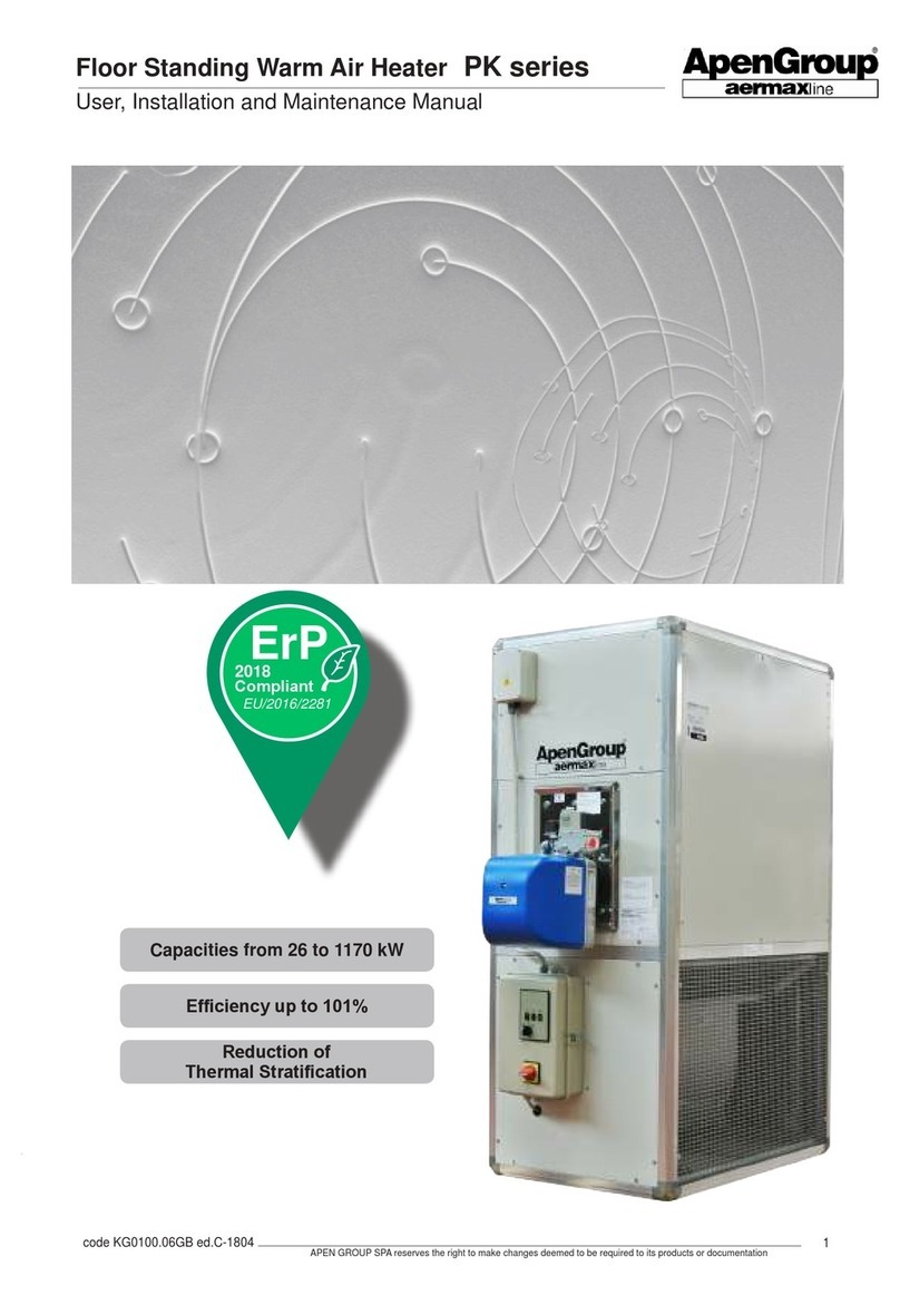
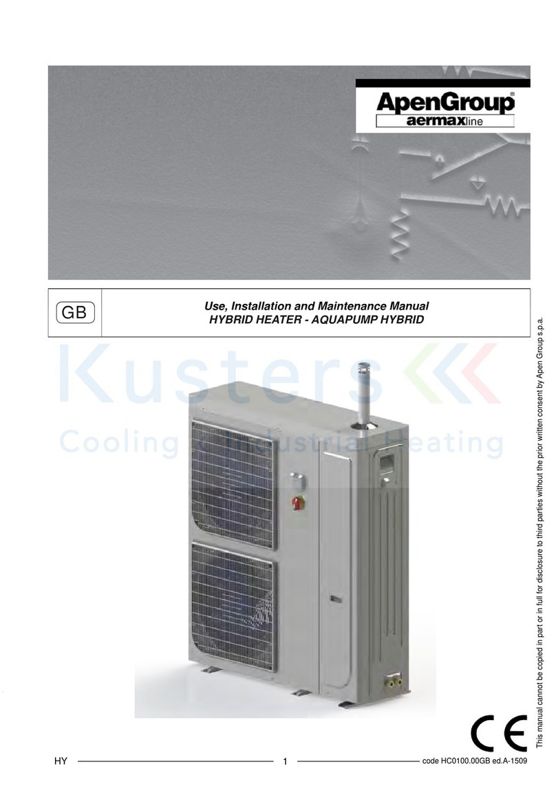
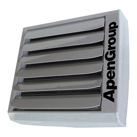
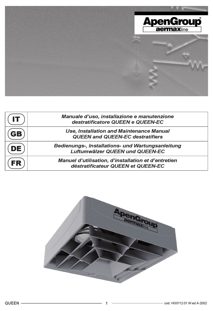
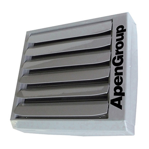
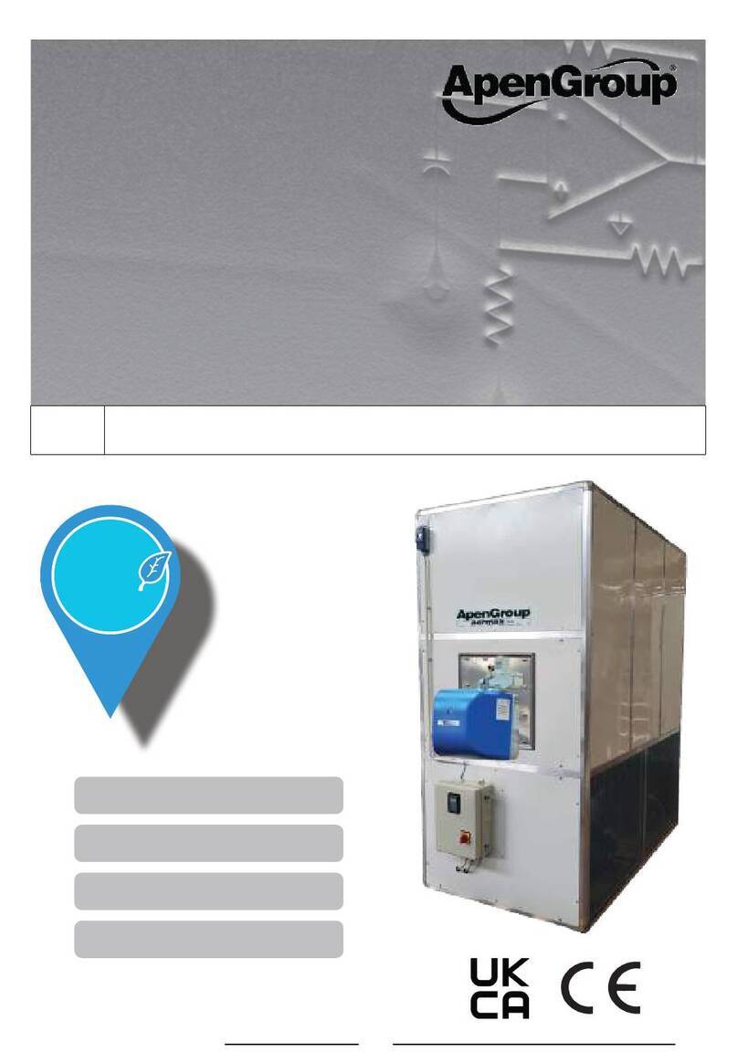
ApenGroup PK Series Operating instructions

1
code HG0320.00GB ed.F-2203 APEN GROUP SPA reserves the right to make changes deemed to be required to its products or documentation
GB User, Installation and Maintenance Manual
PK series oor standing warm air heater with CPU-PLUS
Capacities from 14 to 1170 kW
Eciency up to 101%
Reduction of
Thermal Stratication
ErP
2021
Compliant
EU/2016/2281

code HG0320.00GB ed.F-2203
APEN GROUP SPA reserves the right to make changes deemed to be required to its products or documentation
2
Floor Standing Warm Air Heater PK series
User, Installation and Maintenance Manual
VER. 01.2020
CODE SERIAL NUMBER
Dichiarazione di Conformità
Statement of Compliance
APEN GROUP S.p.A.
20042 Pessano con Bornago (MI)
Via Isonzo, 1
Tel +39.02.9596931 r.a.
Fax +39.02.95742758
Internet: http://www.apengroup.com
Il presente documento dichiara che la macchina:
With this document we declare that the unit:
Modello:
Model:
Generatore a basamento PK PKA-N, PKA-K, PKA-R, PKE-N, PKE-K, PKE-R
Floor Standing Heater PK PKA-N, PKA-K, PKA-R, PKE-N, PKE-K, PKE-R
è stata progettata e costruita in conformità con le disposizioni delle Direttive Comunitarie:
has been designed and manufactured in compliance with the prescriptions of the following EC Directives:
•Regolamento Apparecchi a Gas 2016/426/UE
Gas Appliance Regulation 2016/426/UE
•Direttiva Bassa Tensione 2014/35/UE
Low Voltage Directive 2014/35/UE
•Direttiva Compatibilità elettromagnetica 2014/30/UE
Electromagnetic Compatibility Directive 2014/30/UE
•Regolamento ErP 2016/2281/UE
ErP Regulation 2016/2281/UE
•Direttiva ROHS II 2011/65/UE e ROHS III 2015/863/UE
ROHS II 2011/65/UE and ROHS III 2015/863/UE Directives
Valido solo per gli accoppiamenti generatore-bruciatore indicati dal costruttore (vedere manuale)
Valid only for the heater-burner matching specified by the manufacturer (see manual)
è stata progettata e costruita in conformità con le norme:
has been designed and manufactured in compliance with the standards:
•EN17082:2020
•2017/C 229/01
•EN60335-1
•
EN60335-2-102
Organismo Notificato:
Notified body:
Kiwa Cermet Italia S.p.A
0476
PIN 0476CT2224
La presente dichiarazione di conformità è rilasciata sotto la responsabilità esclusiva del fabbricante
This declaration of conformity is issued under the sole responsibility of the manufacturer
Pessano con Bornago
29/03/2022 Apen Group S.p.A.
Un Amministratore
Mariagiovanna Rigamonti

3
code HG0320.00GB ed.F-2203 APEN GROUP SPA reserves the right to make changes deemed to be required to its products or documentation
Floor Standing Warm Air Heater PK series
User, Installation and Maintenance Manual
INDEX
SECTION 1. GENERAL CAUTIONS......................................................................... 5
SECTION 2. SAFETY-RELATED WARNINGS...................................................... 5
2.1 Fuel....................................................................................................5
2.2 Gas Leaks..........................................................................................5
2.3 Power Supply.....................................................................................6
2.4 Use ....................................................................................................6
2.5 Air Vents ............................................................................................6
2.6 Maintenance......................................................................................6
2.7 Transport and Handling .....................................................................7
2.8 Packaging..........................................................................................7
2.9 Unpacking..........................................................................................8
2.10 Disposal and demolition.....................................................................8
2.11 How to Identify the Heater.................................................................9
SECTION 3. TECHNICAL FEATURES..................................................................... 10
3.1 Main Components..............................................................................10
3.2 Choosing the Heater..........................................................................11
3.3 DiagramsofOutputHeat/EciencyRatioofPK-NHeaters ..............11
3.4 DiagramsofOutputHeat/EciencyRatioofPK-KHeaters ..............12
3.5 DiagramsofOutputHeat/EciencyRatioofPK-RHeaters ..............13
3.6 Technical Data...................................................................................14
3.7 Noise..................................................................................................18
3.8 DimensionsofPKAVerticalHeater ...................................................20
3.9 DimensionsofPKAHorizontalHeater...............................................22
3.10 DimensionsofPKEVerticalHeater ...................................................24
3.11 DimensionsofPKEHorizontalHeater...............................................26
SECTION 4. USER INSTRUCTIONS........................................................................ 28
4.1 Operation...........................................................................................28
4.2 Accessories .......................................................................................29
4.3 Smart Web.........................................................................................30
SECTION 5. SERVICING INSTRUCTIONS............................................................ 34
5.1 Operating cycle..................................................................................34
5.2 Interface Panel...................................................................................34
5.3 Reset .................................................................................................35
5.4 NavigationmapofLCDdisplaymenu ...............................................36
5.5 Modulation PCB parameters..............................................................38
5.6 Analysis of Lockouts..........................................................................41
5.7 SCHNEIDERInverterparametersettings..........................................42
5.8 LGInverterparametersettings..........................................................44
SECTION 6. INSTALLATION INSTRUCTIONS..................................................... 46
6.1 Where to install the Heater................................................................46
6.2 Wiring to Power Supply .....................................................................48
6.3 Electrical Connections.......................................................................49
6.4 Wiring the Burner...............................................................................50
6.5 Optional Accessories .........................................................................51
6.6 Wiring diagrams.................................................................................65
6.7 Burner matching ................................................................................68

code HG0320.00GB ed.F-2203
APEN GROUP SPA reserves the right to make changes deemed to be required to its products or documentation
4
Floor Standing Warm Air Heater PK series
User, Installation and Maintenance Manual
6.8 Gas burners.......................................................................................69
6.9 Burner matching tables......................................................................69
SECTION 7. MAINTENANCE.....................................................................70
7.1 Controls at First Start Up...................................................................70
7.2 RoutineMaintenance.........................................................................71
7.3 Spare Part List...................................................................................72

5
code HG0320.00GB ed.F-2203 APEN GROUP SPA reserves the right to make changes deemed to be required to its products or documentation
Floor Standing Warm Air Heater PK series
User, Installation and Maintenance Manual
1. GENERAL CAUTIONS
This manual is an integral part of the product and must always
accompany it.
Should the equipment be sold or passed on to someone else,
alwaysmakesurethatthismanualissuppliedwiththeequipment
for future reference by the new owner and/or installer.
Themanufacturershallnotbeheldcivillyorcriminallyresponsible
for injuries to people or animals or damages to things caused
by incorrect installation, calibration and maintenance or by
failure to follow the instructions contained in this manual or by
operationscarriedoutbyunqualiedsta.
This product must be used only for the applications for which
itwasdesignedorapproved.Anyotherusemustberegarded
ashazardous.
During the installation, operation and maintenance of the
equipment described in this manual, the user must always
strictlyfollowtheinstructionsgiveninallthechaptersofthis
use and instruction manual.
The condensing warm air heater must be installed
in compliance with current regulations, according to
the manufacturer's instructions and by qualied sta,
technically specialised in the heating eld.
“Firstignition,conversionfromonefamilygas
to another and maintenance must be
carriedoutonlybysuitablyqualiedstaofTechnicalService
Centres
complying with the requisites required by the regulations in
force in their country.
Maintenance must be carried out with methods
andtimingthatcomplywithcurrentandpreviousregulations
in force in the country where the equipment is to be installed.
ForItaly,the“technicalservice”tabofApenGroupwebsitewww.
apengroup.comindicatesseveralTechnicalServiceCentres
thattheusercancontacttohavetherststart-up,adjustment
and maintenance of the product carried out according to law
37/2007 (ex 46/90)
Formoreinformation,visitourwebsite
www.apengroup.com or contact Apen Group directly.
Thewarrantyconditionsarespeciedonthewarrantycerticate
suppliedwiththisequipment.”
2. SAFETY-RELATED WARNINGS
The following symbol is used in this manual to attract machine
operators’ attention.
Safety rules for users or operators of the
equipment and for nearby workers.
Please nd below the safety regulations for the installation
roomandtheairvents.
2.1. Fuel
The heater must be matched to a suitable burner, using the
fuel chosen for the equipment.
The burner shall use the type of fuel it is set for, which is
speciedontheequipmentplateandintechnicalspecications
in burner’s Manual.
In case of a gas burner, the pressure of the gas supplying the
burner and the combustion head must be within the range of
valuesindicatedinthemanual.
Gas oil burners can be used only for N series non-
condensing heaters. For K and R series condensing heaters
use only gas burners.
Before starting the burner/heater, check that:
• the gas mains supply data are compatible with the data
stated on the nameplate;
• thecombustionairissuppliedinsuchawayastoavoid
evenpartialobstructionsoftheintakegrille;
• the gas seal of the feeding system has been tested and
approvedincompliancewiththeapplicablestandards;
• the heater burner is supplied with the same type of fuel it
has been designed for;
• the unit is correctly sized to match required ow rate,
indicatedinthe manual,andincludesallsafetyandcontrol
devicesrequiredbythelaw;
• the inside of the gas pipes and air distribution ducts for
ductedheatershavebeenthoroughlycleaned;
• thefuelowrateissuitableforthepowerrequiredbythe
heater;
• thefuelsupplypressureisbetweentherangespecied
on the nameplate.
When connecting gas supply pipe to gas valve, do not
tighten excessively in order to avoid damaging sealing
gaskets.
2.2. Gas Leaks
If you smell gas:
• donotoperateelectricalswitches,thetelephoneoranyother
objectordevicethatcancausesparksornakedames;
• immediatelyopendoorsandwindowstocreateanairow
toventthegasoutoftheroom;
• closethegasvalves;
• call for qualied sta.
• call the Fire Brigade.
.

code HG0320.00GB ed.F-2203
APEN GROUP SPA reserves the right to make changes deemed to be required to its products or documentation
6
Floor Standing Warm Air Heater PK series
User, Installation and Maintenance Manual
2.3. Power supply
Theheatermustbecorrectlyconnectedtoaneectiveearthing
system,ttedincompliancewithcurrentlegislation.
Cautions:
• Checktheeciencyoftheearthingsystemand,ifrequired,
calloutaqualiedengineer.
• Check that the mains power supply is the same as the
power input stated on the equipment nameplate and in
this manual.
• Donotreverseliveandneutral;theheatercanbeconnected
tothemainspowersupplywithaplug-socketonlyifthe
latterdoesnotallowliveandneutraltobeswapped.
• The electrical system and, more specically, the cable
section, must be suitable for the equipment maximum
power input, shown on the nameplate and in this manual.
• Do not pull electric cables and keep them away from heat
sources.
NOTE:It is compulsory to install, upstream of the power
cable, a switch with a protection (fuses or automatic),
as required by existing regulations. The switch must be
visible, accessible and placed at a distance lower than
3 metres from the control compartment; any electrical
operation (installation and maintenance) must be
performed by qualied sta.
2.4. Use
Do not allow children or inexperienced people to use any
electrically powered equipment.
The following instructions must be followed:
• do not touch the equipment with wet or damp parts of your
body and/or with bare feet;
• donotleavetheequipmentexposedtotheelements(rain,
sun etc...) unless it is adequately protected;
• do not use the gas pipes to earth electrical equipment;
• donotwettheheaterwithwaterorotheruids;
• donotplaceanyobjectovertheequipment;
• donottouchthemovingpartsoftheheater.
Avoidcontactwithhotheatersurfaces.Suchsurfaces,generally
locatedneartheame,overheatduringoperationandremain
hot for some time after the burner has stopped.
If the equipment is not to be used for a certain period of time,
openthe main electrical switchof the thermalstation and close
themanualvalveontheductwhichbringsthe fueltotheburner.
If, instead, the equipment is not to be used any more, perform
the following operations:
• aqualiedpersonshalldisconnectthepowersupplycable
from the main switch;
• closethemanualvalveontheductsupplyingfueltothe
burnerbyremovingorlockingthecontrolhandwheel.
2.5. Air Vents
Theroomwheregasredheaterwillbeinstalledmustbeprovided
withoneormoreairvents.Theseairventsmustbetted
• ushtotheceilingforgaseswithdensitylowerthan0.8sqm;
• ush to the oor for gases with density higher than or
equal to 0.8sqm.
Theairventsmustbettedtowallsfacingtheopenair.The
sectionsmustbesizedaccordingtotheheatoutputinstalled.
In case of doubt, measure the CO2with the burner working at
maximumoutputrateandtheroomventilatedonlythroughthe
airventsfortheburnerandthenmeasureagainwiththedoor
closed. C02valuemustbethesameunderbothconditions.If
inthesameroomthereareseveralburnersoraspiratorsthat
can work together, measure with all the equipment working at
the same time.
Do not obstruct the room air vents, the burner fan intake
opening, any air ductwork and intake or dissipation grilles,
avoidinginthisway:
• stagnationintheroomofanytoxicand/orexplosivemixture;
• smoulderingcombustion:dangerous,expensive,pollutant.
Theheater,ifnotbuiltforoutdoorinstallation,shallbesheltered
from rain, snow, and frost. If air is pulled from outdoor, the
intakemustbeprotectedbyaraindeectororsimilardevice
thatpreventswaterfrompenetratingintotheheater.
Theroomwheretheheater-burnergroupisinstalledmustbe
cleananddeprivedofvolatilesubstancesthatcanbedrawnby
the fan and obstruct burner inner hoses or combustion head.
Dust itself can be a problem if it is left depositing on fan blades,
thusreducingfanowrateandmakingcombustionpolluting.
Moreoverdustcandepositonthebackofamestabilitydisk
incombustionhead,degradingair-fuelmixingratio.
2.6. Maintenance
Before carrying out any cleaning and maintenance operations,
isolate the boiler from the mains power supply using the switch
locatedontheelectricalsystemand/orontheshut-outdevices.
If the equipment is faulty and/or incorrectly operating, switch it
oanddonotattempttorepairityourself,butcontactourlocal
TechnicalServiceCentre.
All repairs must be carried out by using genuine spare parts.
Failuretocomplywiththeaboveinstructionscouldcompromise
thesafetyoftheequipmentandinvalidatethewarranty.
7
code HG0320.00GB ed.F-2203 APEN GROUP SPA reserves the right to make changes deemed to be required to its products or documentation
Floor Standing Warm Air Heater PK series
User, Installation and Maintenance Manual
2.7. Transport and Handling
Verticalheatersaredeliveredfastenedtoapallet.Horizontal
heatershavetheirownbase.
Unloadtheheater fromthetruckandmove ittothesiteof
installation by using means of transport suitable for the shape
and for the weight of the load.
Any lifting and transport operations must be carried out by
skilledsta,adequatelytrainedandinformedontheworking
procedures and safety regulations. Instructions in this Manual
shallhavetobefollowedwhenhandlingtheexchanger.
Based on their weight and dimensions, heaters can be lifted
withlifttrucksorwheel-mountedcrane.
KG0100C3020
Intherstcase,useforkextensionsaslongasheaterwidth.
If a crane is to be used, insert in holes in heater base rods with
asuitableliftingresistanceandinstallprotectionstoprevent
crane ropes from damaging heater body.
Once the equipment is moved to the correct position, the
unpacking operation can be started.
KG0100C3022
2.8. Packaging
The unpacking operation must be carried out by using suitable
toolsorsafetydeviceswhererequired.Recoveredpackaging
materials must be separated and disposed of according to
applicable regulations in the country of use.
While unpacking the unit, check that the unit and all its parts
havenotbeendamagedduringtransportandmatchtheorder.
Ifdamageshaveoccurredorpartsarefoundtobemissing,
immediately contact the supplier.
The manufacturer is not liable for any damages occurred
during transport, handling and unloading.

code HG0320.00GB ed.F-2203
APEN GROUP SPA reserves the right to make changes deemed to be required to its products or documentation
8
Floor Standing Warm Air Heater PK series
User, Installation and Maintenance Manual
2.9. Unpacking
The unpacking operation must be carried out by using suitable
toolsorsafetydeviceswhererequired.Recoveredpackaging
materials must be separated and disposed of according to
applicable regulations in the country of use.
While unpacking the unit, check that the unit and all its parts
havenotbeendamagedduringtransportandmatchtheorder.
Ifdamageshaveoccurredorpartsarefoundtobemissing,
immediately contact the supplier.
The manufacturer is not liable for any damages occurred
during transport, handling and unloading.
Packing material disposal
The packing safeguards the product from transport damages.
All the materials used are environmentally friendly and
recyclable. Please contact a specialised distributor or your
local administration for more information on waste disposal.
2.10. Dismantling and demolition
Should the machine be dismantled or demolished, the person
in charge with the operation shall proceed as follows:
Disposal of end-of-life products
This equipment is marked in compliance with
European Directive 2012/19/EU on waste
electrical and electronic equipment (WEEE).
This Directive denes the rules for collecting
and recycling waste equipments throughout the
entire territory of the European Union.
WEEE contains both pollutants (that can
negatively aect the environment) and raw materials (that
can be reused). IT is therefore necessary to subject WEEE to
appropriatetreatments,inordertoremoveandsafelydispose
of pollutants and to extract and recycle raw materials. IT is
forbidden to dispose of WEEE as unsorted waste. These
operationsfacilitaterecoveryandrecyclingofthematerials,
thusreducingtheenvironmentalimpact.
NOTE: All materials recovered will be processed and
disposed of according to what provided for by the laws
in force in the country of use and/or according to the
standards indicated in the safety sheets of the chemicals.
INFORMATION FOR DISPOSAL valid in ITALY
(Legislative Decree 49/2014)
The AH series air handling units and relating accessories
are considered “professional WEEE - waste electrical and
electronic equipment”. According to the legislation in force
in Italy, professional WEEE must be sent to treatment plants
suitable for these types of waste. Please contact the Apen
Groupforend-of-lifeproductssoastoobtainalltheinformation
necessary for their correct waste disposal, which is possible
thankstotheCollectiveSystem(Union)towhichthecompany
is associated. Please remember that product disposal without
complyingwiththemodedescribedaboveisaviolationliable
toadministrativeandpenalsanctions.
INFORMATION FOR DISPOSAL valid abroad
(EU COUNTRIES except Italy).
TheEuropeanDirective2012/19/ECshallbeimplementedin
everyEUmemberstate.Theremaybedierentapplication
modalities for the various member states, even in terms of
modalityforwastedisposaldependingonitstype(House-hold
or Professional WEEE). To this regard at the end of the life of
the product, we highly recommend you call the distributor or
installer so as to obtain information on the correct disposal, in
compliance with the existing laws of the installation country.

9
code HG0320.00GB ed.F-2203 APEN GROUP SPA reserves the right to make changes deemed to be required to its products or documentation
Floor Standing Warm Air Heater PK series
User, Installation and Maintenance Manual
2.11. How to Identify the Heater
PKwarmairheaterscanbeidentiedusingtheirnameplate,
stuck on the front of the unit.
The nameplate shows all the data needed for identifying the
heater model.
WhenrequiredbyServiceCentre,read the heater model and
serial number on the nameplate, which identify your unit.
Heater Code
PK A 250 N - 2 H W
Heater
Version:
A (indoor);
E (outdoor).
Capacity
Series:
Standardnon-condensingNseries
CondensingKseries
CondensingRseries
Available Head Pressure (valuesareshownintableswithtechnicalfeatures):
0-LowHeadPressure;
1-MediumHeadPressure;
2-HighHeadPressure.
Installation:
H-Horizontal
0-Vertical
Control panel implemented for accessory management

code HG0320.00GB ed.F-2203
APEN GROUP SPA reserves the right to make changes deemed to be required to its products or documentation
10
Floor Standing Warm Air Heater PK series
User, Installation and Maintenance Manual
3. TECHNICAL FEATURES
3.1. Main Components
Warm air heaters include:
• stainless steel heat exchanger
• frame and body
• centrifugal fan and electrical motor
• control panel and settings
• safetydevicesandcontrols
Stainless steel heat exchanger
Theinnovativedesignandlargesurfaceof the combustion
chamberandheatexchangerpipesensureoptimumeciency
and durability.
Combustionchamberanduegascollectorsarecompletely
made of AISI 441 stainless steel with low carbon content, as
wellasthesurfacesincontactwithuegases(tubebundle)in
order to ensure a high resistance to corrosion.
Tube bundle design is patented.
Characteristics of steel types used
Thefollowing table shows naming correspondenceof the steel
types used to manufacture our exchangers:
USA-AISI EN-No. Composition
AISI441 1.4509 X2CrTiNb18
AISI310* 1,4845 X8CrNi25-21
AISI304* 1,4301 X5CrNi18-10
*Exchangersbuiltwithdierentmaterials,suchasAISI310or
304, can be taken into account for special applications.
Heater’sheatexchangercanworkalsounderconditionsthatlead
to condensation (if equipped with the necessary accessories)
onlyiftherelevantburnerissuppliedwithgaseousfuel.
Frame and body
The frame consists of solid anodised aluminium bars. The
frameisassembledwithdemountablepartsallowing,inspecial
cases such as door crossing, to disassemble and reassemble
the heater completely.
Body panels are formed by:
-ontheexchangerside:riveteddouble-layeredpanelswith
innergalvanizedsteelsheet,high-densityglassbreinsulation,
externalpaintedgalvanizedsteelsheet.
-onthefanside:paintedgalvanizedsteelsheetwithinnerlayer
forthermalandsoundisolation,securelyfastenedtosteelpanel.
Allpanelsfeatureagasketforaperfectsealingagainstairleaks.
Centrifugal Fan
Standardcentrifugalfansinstalledaremadeofgalvanisedsteel
sheetwithforwardcurvedbladesandlownoiseofoperation.
Fansarexedonhermeticballbearingswhichareself-aligned
andassembledinsiderubberdampers.Twotypesoffanareused:
• directdrivefans:themotorisdirectlycoupledtothefan.
They are used on heaters with single phase power supply
(PKA060-00W)
• fansforsquareduct:drivenbymeansofxeddiameter
pulleysandbelts,three-phasemotor.
Nolubricationisrequiredonstandardfans.Forspecialfans,
checkspecicrequirements.
Operating Temperatures:
A- directdrive -20°C +40°C
B- beltdrive -20°C +85°C
Thefollowingfansareavailableondemand:
• backwardcurvedblades
• plugfan,directlydrivenbythemotorandcontrolledthrough
inverter
• fansfortemperatureslowerthan-20°C
Electrical Motor
Allmotorsused,exceptthosewithdirectdrivetothefan,have
the following characteristics:
• Supply 400Vac-Three-phase-50Hz
• Structure B3-withterminalboardabove
• Protection degree IP55
• Isolationlevel cl.F
• Eciency IE3
Formoremodel-relatedinformationonmotors,seefurtherin
this Manual.
If required, motors with the following characteristics can be
supplied:
• varioussupplyvoltages,electricalfeaturesandphysical
shapes;
• motorsforlowtemperatures(below-30°C)
• motors with class H isolation
• tropicalised motors
• motors with internal heat protection, thermostat, or PT100
or PTC probe.
Control Panel and Settings
Standard control panel includes:
• oven-varnishedmetalbox
• quadripolarswitch-disconnector,padlockable, with door
lock
• protectionfromoverheatandshortcircuitforeachmotor
• fuse-protectedwiringboardtocontrolheater,safetydevices
and burner.
• for motors with power equal to or greater than 5.5 kW it is
supplied with soft starter.
The setting depends on the burner installed. The following
typesareavailable:
• ON-OFF
• high/lowame
• modulating.
Safety Devices and Controls
All heaters are supplied with the following thermostats:
-STB Manualresetsafetythermostat,insidetheairow,
whichswitchesotheburnerimmediatelyifthetemperature
is high.
-NTC NTCprobemodulatesand/orstopstheburneroperation
beforethesafetythermostatactivates.

11
code HG0320.00GB ed.F-2203 APEN GROUP SPA reserves the right to make changes deemed to be required to its products or documentation
Floor Standing Warm Air Heater PK series
User, Installation and Maintenance Manual
3.2. Choosing the Heater
Heatersareavailableincondensingversions(KandRseries
respectively)andinnon-condensingversion(Nseries).Rseries
meets the eciency requests of the regional resolutions of
Lombardy,EmiliaRomagnaandPiedmont;atEuropeanlevel,
amatchingwithlowNOxburnersisrequiredinordertocomply
with the imposed regulatory limitations.
Heatersforindoorinstallation(PKA)aresuppliedwithexchanger,
fanunitand controlpaneltobeinstalledindoororinasheltered
position; those for outdoor installation (PKE) are supplied with
exchanger, fan unit, control panel and burner casing to be
positioned outdoor.
Aworkeldhasbeentestedandapprovedforeachheater.
This eld allows the heater to be used at dierent power
andeciencylevelsbasedoneectiveoutputpower.When
choosingaheatermodel,thefollowingcriteriahavetobetaken
intoaccount:itsuse(heating,processplant,orother),service
type(seasonorallyearlong),matchingburnertype(on-o,
two stages or modulating).
3.3. Diagrams of Output Heat/Eciency Ratio of PK-N Heaters
KG0100EG011 KG0100EG011_A
Power - Eciency
Heat output kW
Eciency%
250
190
140
87
88
89
90
91
92
93
94
95
96
50 100 150 200 250 300 350 400 450 500 550 600 650 700 750 800 850 900 950 1000 1050 1100
Rendimento%
PotenzaTermicakW
Potenze - Rendimenti
550
320
700
900
42
0
1M2

code HG0320.00GB ed.F-2203
APEN GROUP SPA reserves the right to make changes deemed to be required to its products or documentation
12
Floor Standing Warm Air Heater PK series
User, Installation and Maintenance Manual
3.4. Diagrams of Output Heat/Eciency Ratio of PK-K Heaters
90
92
94
96
98
100
102
104
106
108
50 100 150 200 250 300 350 400 450 500 550 600 650 700 750 800 850 900 950 1000 1050 1100
Rendimento%
PotenzaTermicakW
Potenze -Rendimenti
550
320
700
900
420
1M2
Heat output kW
Eciency%
Power - Eciency
KG0100EG008
90
92
94
96
98
100
102
104
020 40 60 80 100 120 140 160 180 200 220 240 260
Rendimento%
PotenzaTermicakW
Potenze -Rendimenti
140
100
060
190
250
032
Power - Eciency
Heat output kW
Eciency%
KG0100EG006

13
code HG0320.00GB ed.F-2203 APEN GROUP SPA reserves the right to make changes deemed to be required to its products or documentation
Floor Standing Warm Air Heater PK series
User, Installation and Maintenance Manual
3.5. Diagrams of Output Heat/Eciency Ratio of PK-R Heaters
92
94
96
98
100
102
104
020 40 60 80 100 120 140 160 180 200 220
Rendimento%
PotenzaTermicakW
Potenze -Rendimenti
140
100
060
190
250
032
Heat output kW
Eciency%
Power - Eciency
KG0100EG009
Heat output kW
Eciency%
Power - Eciency
KG0100EG010
94
95
96
97
98
99
100
101
102
103
104
50 100 150 200 250 300 350 400 450 500 550 600 650 700 750 800
Rendimento%
PotenzaTermicakW
Potenze -Rendimenti
550
320
700
900
420

code HG0320.00GB ed.F-2203
APEN GROUP SPA reserves the right to make changes deemed to be required to its products or documentation
14
Floor Standing Warm Air Heater PK series
User, Installation and Maintenance Manual
3.6. Technical Data
Technical data table for PKA, PKE Series N. Technical data for PKA-N and PKE-N models are the same.
Heat Input and Eciency Data
Model PKA140N PKA190N PKA250N PKA320N PKA420N
Type of appliance B23
ECapproval 0476CT2224
NOxClass NOxCLASS 5**
MIN MAX MIN MAX MIN MAX MIN MAX MIN MAX
Furnace Heat Input Pmin;
Pated,h kW 96.0 195.0 115 230.0 154.0 310.0 185.0 380.0 260 508
Useful Heat Output kW 90.2 171.0 108.1 205.9 145.0 275.0 173.9 335.9 245 450
CombustionEciency(Hi) ηpl;
ηnom
%94.0 87.7 94.0 89.5 94.0 88.7 94.0 87.7 94.4 88.6
CombustionEciency(Hs) % 84.7 79.0 84.7 80.6 84.7 79.9 84.7 79.0 85.0 79.8
Seasonal heating energy
efficiency ηs,h %According to the chosen burner: see table in Par. 6.9
Output efficiency ηs,flow %According to the chosen burner: see table in Par. 6.9
Chimneyloss-BurnerON(Hi) % 6.0 12.3 6.0 10.5 6.0 12.3 6.0 12.3 5.6 11.4
Chimneyloss-BurnerOFF % < 0.1 <0,1 <0,1 < 0.1 < 0.1
Casing losses *Fenv %1.26 1.16 1.17 1.02 1.03
Combustion Chamber pressure Pa 13 50 10 40 10 50 15 60 28 120
CombustionChambervolume m30.37 0.52 0.76 1.06 1.55
Model PKA550N PKA700N PKA900N PKA1M2N
Type of appliance B23
ECapproval 0476CT2224
NOxClass NOxCLASS 5**
MIN MAX MIN MAX MIN MAX MIN MAX
Furnace Heat Input Pmin;
Pated,h
kW 320 670 397 818 447 1028 617 1170
Useful Heat Output kW 301 592 374 730 422 920 583.7 1049.5
CombustionEciency(Hi) ηpl;
ηnom
%94.3 88.4 94.3 89.3 94.4 89.5 94.6 89.7
CombustionEciency(Hs) % 85.0 79.6 85.0 80.5 85.0 80.6 85.2 80.8
Seasonal heating energy
efficiency ηs,h %According to the chosen burner: see table in Par. 6.9
Output efficiency ηs,flow %According to the chosen burner: see table in Par. 6.9
Chimneyloss-BurnerON(Hi) % 5.7 11.6 5.7 10.7 5.6 10.5 5.6 10.5
Chimneyloss-BurnerOFF % < 0.1 < 0.1 < 0.1 < 0.1
Casing losses *Fenv %0.97 1.00 1.01 1.01
Combustion Chamber pressure Pa 21 110 25 120 28 130 53 205
CombustionChambervolume m31.79 4.78 5.58 5.58
*Heatlossofthecasingmustbeconsideredonlywhenheateris
installedoutdoororinathermalstation.Iftheheaterisinstalled
intoabuilding,heatisirradiatedinside,solossesarezero.
**WithCLASS3GASBURNERSaccordingtoEN676

15
code HG0320.00GB ed.F-2203 APEN GROUP SPA reserves the right to make changes deemed to be required to its products or documentation
Floor Standing Warm Air Heater PK series
User, Installation and Maintenance Manual
Technical data table for PKA, PKE Series K. Technical data for PKA-K and PKE-K models are the same.
Heat Input and Eciency Data
Model PKA032K PKA060K PKA100K PKA140K PKA190K PKA250K
Type of appliance B23
ECapproval 0476CT2224
NOxClass NOxCLASS 5**
MIN MAX MIN MAX MIN MAX MIN MAX MIN MAX MIN MAX
Furnace Heat Input Pmin;
Pated,h
kW 14 34.6 22.0 72.0 26.5 114 38.0 152.0 48.0 200.0 61.0 270.0
Useful Heat Output kW 14.3 32.0 22.5 66.5 27.1 105.4 38.5 140.8 48.3 182.2 61.6 248.9
CombustionEciency(Hi) ηpl;
ηnom
%102.5 92.5 102.4 92.4 102.4 92.5 101.2 92.6 100.5 92.6 101.0 92.2
CombustionEciency(Hs) % 92.3 83.3 92.3 83.2 92.3 83.3 91.2 83.4 90.5 83.4 91.0 83.1
Seasonal heating energy
efficiency ηs,h %According to the chosen burner: see table in Par. 6.9
Output efficiency ηs,flow %According to the chosen burner: see table in Par. 6.9
Chimneyloss-BurnerON(Hi) % 7.5 7.6 7.5 7.4 7.4 7.8
Chimneyloss-BurnerOFF % < 0.1 < 0.1 < 0.1 < 0.1 <0,1 < 0.1
Casing losses *Fenv %2.61 1.64 1.81 1.26 1.16 1.17
Combustion Chamber pressure Pa 8 40 12 100 14 100 15 140 15 130 19 175
CombustionChambervolume m30.06 0.12 0.24 0.37 0.52 0.76
Model PKA320K PKA420K PKA550K PKA700K PKA900K PKA1M2K
Type of appliance B23
ECapproval 0476CT2224
NOxClass NOxCLASS 5**
MIN MAX MIN MAX MIN MAX MIN MAX MIN MAX MIN MAX
Furnace Heat Input Pmin;
Pated,h
kW 74.0 347.0 83.0 455.0 95.0 595.0 126.0 756.0 175.0 974.0 175.0 1130.0
Useful Heat Output kW 74.8 319.8 83.8 419.4 96.1 549.1 127.6 697.2 179.7 900.0 186.0 1057.7
CombustionEciency(Hi) ηpl;
ηnom
%101.0 92.2 101.0 92.2 101.2 92.3 101.3 92.2 102.7 92.4 106.3 93.6
CombustionEciency(Hs) % 91.0 83.1 91.0 83.1 91.2 83.2 91.3 83.1 92.5 83.24 95.77 84.32
Seasonal heating energy
efficiency ηs,h %According to the chosen burner: see table in Par. 6.9
Output efficiency ηs,flow %According to the chosen burner: see table in Par. 6.9
Chimneyloss-BurnerON(Hi) %8.7 7.8 7.7 7.8 7.6 7.6
Chimneyloss-BurnerOFF % < 0.1 < 0.1 < 0.1 < 0.1 < 0.1 < 0.1
Casing losses *Fenv %1.02 1.03 0.97 1.00 1.01 1.01
Combustion Chamber pressure Pa 15 225 30 275 40 365 45 410 45 420 60 615
CombustionChambervolume m31.06 1.55 1.79 4.78 5.58 5.58
*Heatlossofthecasingmustbeconsideredonlywhenheateris
installedoutdoororinathermalstation.Iftheheaterisinstalled
intoabuilding,heatisirradiatedinside,solossesarezero
**WithCLASS3GASBURNERSaccordingtoEN676

code HG0320.00GB ed.F-2203
APEN GROUP SPA reserves the right to make changes deemed to be required to its products or documentation
16
Floor Standing Warm Air Heater PK series
User, Installation and Maintenance Manual
Technical data table for PKA, PKE Series R. Technical data for PKA-R and PKE-R models are the same.
Heat Input and Eciency Data
Model PKA032R PKA060R PKA100R PKA140R PKA190R PKA250R
Type of appliance B23
ECapproval 0476CT2224
NOxClass NOxCLASS 5**
MIN MAX MIN MAX MIN MAX MIN MAX MIN MAX MIN MAX
Furnace Heat Input Pmin;
Pated,h
kW 14.0 32.0 22.0 58.0 26.5 90.0 38.0 115.9 48.0 162.0 61.0 217.0
Useful Heat Output kW 14.3 29.6 22.5 53.8 27.1 84.8 38.5 113.4 48.3 150.6 61.6 205.5
CombustionEciency(Hi) ηpl;
ηnom
%102.5 93.2 102.4 93.6 102.4 94.1 101.2 94.2 100.5 94.5 101.0 94.7
CombustionEciency(Hs) % 92.3 84.0 92.3 84.3 92.3 84.8 91.2 84.9 90.5 85.1 91.0 85.3
Seasonal heating energy
efficiency ηs,h %According to the chosen burner: see table in Par. 6.9
Output efficiency ηs,flow %According to the chosen burner: see table in Par. 6.9
Chimneyloss-BurnerON(Hi) % 7.5 7.6 7.5 7.4 7.4 7.8
Chimneyloss-BurnerOFF % < 0.1 < 0.1 < 0.1 < 0.1 <0,1 < 0.1
Casing losses *Fenv %2.61 1.64 1.81 1.26 1.16 1.17
Combustion Chamber pressure Pa 8 40 12 100 14 100 15 140 15 130 19 175
CombustionChambervolume m30.06 0.12 0.24 0.37 0.52 0.76
Model PKA320R PKA420R PKA550R PKA700R PKA900R
Type of appliance B23
ECapproval 0476CT2224
NOxClass NOxCLASS 5**
MIN MAX MIN MAX MIN MAX MIN MAX MIN MAX
Furnace Heat Input Pmin;
Pated,h
kW 74.0 275.0 83.0 345.0 95.0 450.0 126.0 599.0 175.0 760.0
Useful Heat Output kW 74.8 256.5 83.8 325.8 96.1 430.1 127.6 571.4 179.7 723.4
CombustionEciency(Hi) ηpl;
ηnom
%101.0 94.9 101.0 95.2 101.2 95.3 101.3 95.4 102.7 95.4
CombustionEciency(Hs) % 91.0 85.5 91.0 85.8 91.2 85.9 91.3 85.9 92.5 85.95
Seasonal heating energy
efficiency ηs,h %According to the chosen burner: see table in Par. 6.9
Output efficiency ηs,flow %According to the chosen burner: see table in Par. 6.9
Chimneyloss-BurnerON(Hi) %7.7 7.8 7.7 7.8 7.6
Chimneyloss-BurnerOFF % < 0.1 < 0.1 < 0.1 < 0.1 < 0.1
Casing losses *Fenv %1.03 1.03 0.97 1.00 1.01
Combustion Chamber pressure Pa 23 225 30 275 40 365 45 410 45 420
CombustionChambervolume m31.06 1.55 1.79 4.78 5.58
* Heatloss of the casingmustbe considered only whenheater
is installed outdoor or in a thermal station. If the heater is
installedintothebuildingtobeheated,heatisirradiated inside,
socasinglossesarezero
** WithCLASS3GASBURNERSaccordingtoEN676

17
code HG0320.00GB ed.F-2203 APEN GROUP SPA reserves the right to make changes deemed to be required to its products or documentation
Floor Standing Warm Air Heater PK series
User, Installation and Maintenance Manual
Air ow rate technical data, head pressure and installed power supply.
Values of PKA and PKEareidentical,aswellasvaluesofN, Kand Rseries
Model PKA032 PKA060 PKA100 PKA140 PKA190
Version 10A 10A 20A 10A 20A 10A 20A 10A 20A
AirFlowRate-15°C m3/h 2,700 5000 7300 10500 14000
AvailableHeadPressure Pa 150 120 240 150 270 140 280 150 230
Heat drop Min and Max* K 26.8-32.5 26.0-41.7 28.3-38.0 23.8-45.2 23.4-40.8
Power supply V 230M 400T+N 400T+N 400T+N 400T+N
Frequency Hz 50
Motor Max. capacity ** kW 0.35 1.1 1.5 1.5 2.2 3.0 4.0 3.0 4.0
Max. Absorbed power*** kW 0.56 1.44 1.91 1.91 2.72 3.63 4.73 3.63 4.73
ProtectionRating IP PKASeries=IP20,PKESeries=IP24;PKAControlPanel=IP44,PKE=IP54
Runningtemperature °C from-20°Cto+40°C(checkrunningtemperatureofmatchingburner)
Model PKA250 PKA320 PKA420 PKA550 PKA700
Version 10A 20A 10A 20A 10A 20A 10A 20A 10A 20A
AirFlowRate-15°C m3/h 18,000 23000 30000 40000 54000
AvailableHeadPressure Pa 130 250 210 320 180 270 180 280 240 350
Heat drop Min and Max* K 22.4-42.4
9.5-38.4(Series
K)
21.1-40.5
9.0-38.6(Series
K)
22.3-40.9
7.8-38.8(Series
K)
21.0-41.0
6.7-38.0(Series
K) 19.9-38.8
Power supply V 400T+N 400T+N 400T+N 400T+N 400T+N
Frequency Hz 50
Motor Max. capacity ** kW 2x2.2 2x3.0 2x3.0 2x4.0 2x5.5 2x5.5 2x4.0 2x5.5 2x5.5 2x7.5
Max. Absorbed power*** kW 5.43 7.26 7.26 9.46 12.8 12.8 9.46 12.8 12.8 17.1
ProtectionRating IP PKASeries=IP20,PKESeries=IP24;PKAControlPanel=IP44,PKE=IP54
Runningtemperature °C from-20°Cto+40°C(checkrunningtemperatureofmatchingburner)
Model PKA900 PKA1M2
Version 10A 20A 10A 20A
AirFlowRate-15°C m3/h 68,500 74000
AvailableHeadPressure Pa 260 400 260 400
Heat Drop Min and Max K 18.8-38.5 24.4-43.9
7.8-44.3(SeriesK)
Power supply V 400T+N 400T+N
Frequency Hz 50
Motor Max. capacity ** kW 2x9.2 2x11.0 2x11.0 2x15.0
Max. Absorbed power*** kW 20.7 24.8 24.3 32.8
ProtectionRating IP PKASeries=IP20,PKESeries=IP24;
PKAControlPanel=IP44,PKE=IP54
Runningtemperature °C from-20°Cto+40°C(checkrunning
temperature of matching burner)
* Minimum heat drop is referred to minimum heat input, while
maximum heat drop refers to maximum heat input
** Max.capacityreferstothemaximumpowerdeliveredby
themotor;asfortheheater,thepoweractuallydeliveredby
the motor depends on the fan working position with respect to
the air distribution system’s drops (system drops)
*** Maximum absorbed power refers to the maximum power
deliveredbythemotormultipliedbythesuppliedmotoreciency
(eciencyIE3);thepowerabsorbedbythematchingburner
mustbeaddtothevalueindicatedinthetable.

code HG0320.00GB ed.F-2203
APEN GROUP SPA reserves the right to make changes deemed to be required to its products or documentation
18
Floor Standing Warm Air Heater PK series
User, Installation and Maintenance Manual
3.7. Noise
HEATERS INSTALLED INDOOR
Thefollowingtableshowssoundpressurevalues
(LpA), issued by PK-A heaters 00W version,
installed as follows:
• standard distribution plenum;
• air intake turned towards a wall, without
lters;
• indoor installation.
Sound pressure value refers to the heater
standard installation with the long side adjacent
to a wall and the plenum with air blowing on one
long side and 3 short sides.
Theestimatedvalueonlyreferstotheamountof
sound directly produced by the heater.
Any sound source in a closed surrounding
producesasoundlevelthatisthesumofdirect
anddiusesounds.Directsoundistheoutput
from the source while diuse sound depends
on the acoustic characteristics of the installation
room (size, average sound absorption, etc.).
Obviously,theincidenceofdiusesoundover
directsoundisgreaterasthedistancefromsound
source grows.
InPK-Aheatersforindoorinstallation,thenoise
generated on intake by centrifugal fans is the
maincomponentofnoiseproducedbytheheater,
sinceonlyaprotectivegridisinstalled.
Thevalueondeliveryislowersinceexchanger,
panelling and plenum help reducing it.
Detectiondistanceforsoundpressureinthetable
changesaccordingtoheatersize.
Noise level is the same in N series and K series heaters.
Model Distance LpA - Sound Pressure Level [dB(A)] dB(A)
metres 63 125 250 500 1000 2000 4000 8000
PKA032-00A 6 18.6 32.6 38.5 43.2 47.0 46.6 39.2 32.5 51.3
PKA060-00A 6 24.3 38.8 44.0 46.0 48.7 48.1 43.1 36.0 53.7
PKA100-00A 6 28.8 43.3 48.5 50.5 53.2 52.6 47.6 40.5 58.2
PKA120-00A 6 28.8 43.3 48.5 50.5 53.2 52.6 47.6 40.5 58.2
PKA140-00A 9 27.3 41.8 47.0 49.0 51.7 51.1 46.1 39.0 56.8
PKA190-00A 9 29.7 44.2 49.4 51.4 54.7 53.5 48.5 41.4 59.4
PKA250-00A 9 28.1 42.6 47.8 49.8 52.5 51.9 46.9 39.8 57.6
PKA320-00A 9 30.3 44.8 50.0 52.0 54.7 54.1 49.1 42.0 59.8
PKA420-00A 12 35.3 49.8 55.0 57.0 59.7 59.1 54.1 47.0 64.8
PKA550-00A 12 32.0 41.3 47.2 49.0 47.9 47.4 42.6 35.0 54.6
PKA700-00A 12 32.7 40.8 46.5 49.6 50.9 49.9 43.8 34.9 56.0
PKA900-00A 12 39.6 43.2 52.6 51.0 54.8 50.5 44.4 37.5 59.0
PKA1M2-00A 12 43.6 47.5 57.9 56.1 60.3 55.6 48.8 41.3 64.9

19
code HG0320.00GB ed.F-2203 APEN GROUP SPA reserves the right to make changes deemed to be required to its products or documentation
Floor Standing Warm Air Heater PK series
User, Installation and Maintenance Manual
DUCTED HEATERS
Thefollowingtableshowssoundpowervalues,
LwA,andsoundpressurevalues,LpA, issued
byPKA/Eheatersof10Wand20Wversions.
Thevaluereferstoheaterswithductedintake
anddelivery.
ThevaluesinthetablerefertoLwApower,which
passes through the heater sandwich panels.
Detection distances for sound pressure have
beenchangedaccordingtoheatersize.
Forthevaluesoffannoiseinductsforairintake
anddelivery,contactAPENGROUPTechnical
Support.
Noise level is the same in N series and K series heaters.
Heater with ducted delivery and intake
MODEL LwA - Sound Power Level [dB(A)] LwA distance LpA
63 125 250 500 1000 2000 4000 8000 dB(A) metres dB(A)
PK032-10A 37.9 51.9 52.1 52.5 51.4 47.0 37.7 30.1 58.4 4 35.4
PK060-10A 42.7 57.2 56.7 55.9 54.1 49.3 41.6 33.0 62.5 4 39.4
PK060-20A 44.6 59.1 58.6 57.8 56.0 51.2 43.5 34.9 64.4 4 41.3
PK100-10A 47.4 61.9 61.4 60.6 58.8 54.0 46.3 37.7 67.2 4 44.1
PK100-20A 48.4 62.9 62.4 61.6 59.8 55.0 47.2 38.7 68.2 4 45.1
PK140-10A 48.8 63.3 62.8 62.0 60.2 55.4 47.7 39.2 68.6 4 45.5
PK140-20A 50.0 64.5 64.0 63.2 61.4 56.6 48.9 40.3 69.8 4 46.7
PK190-10A 51.6 66.1 65.6 64.8 63.0 58.2 50.5 41.9 71.4 6 44.8
PK190-20A 53.0 67.5 67.0 65.9 64.4 59.6 51.9 43.3 72.7 6 46.1
PK250-10A 49.9 64.4 63.9 63.1 61.3 56.5 48.3 40.2 69.6 6 43.1
PK250-20A 52.4 66.9 66.4 65.7 63.8 59.0 51.3 42.7 72.2 6 45.6
PK320-10A 54.3 68.8 68.3 67.6 65.7 61.0 53.2 44.6 74.1 6 47.5
PK320-20A 55.4 69.9 69.4 68.7 66.8 62.0 54.3 45.7 75.2 6 48.6
PK420-10A 58.9 73.4 72.9 72.2 70.3 65.5 57.8 49.2 78.7 10 47.7
PK420-20A 59.9 74.4 73.9 73.2 71.3 66.5 58.8 50.2 79.7 10 48.7
PK550-10A 58.3 68.0 64.2 63.5 57.6 53.9 46.1 37.1 71.0 10 40.0
PK550-20A 64.7 68.2 64.3 64.5 58.1 53.8 46.5 37.7 72.0 10 41.0
PK700-10A 57.8 67.1 65.2 63.2 61.3 56.4 47.4 36.9 71.1 10 40.1
PK700-20A 59.7 70.5 67.3 65.8 62.9 57.3 49.1 39.1 73.8 10 42.8
PKA900-10A
PKA1M2-10A 62.5 68.9 70.5 67.3 61.5 57.3 48.3 39.6 74.5 10 43.5
PKA900-20A 63.1 72.4 70.8 69.8 63.3 58.8 50.1 40.9 76.4 10 45.4
PKA1M2-20A 69.4 79.6 77.9 76.8 69.6 64.7 55.1 45.0 84.0 10 49.9

code HG0320.00GB ed.F-2203
APEN GROUP SPA reserves the right to make changes deemed to be required to its products or documentation
20
Floor Standing Warm Air Heater PK series
User, Installation and Maintenance Manual
3.8. Dimensions of PKA Vertical Heater
INDOOR VERTICAL HEATERS (Series N, K and R)
KG0100C2001
C
Model Overall dimensions Intake Delivery Prole Chimney Burner Weight
L B H Hb A E A D P G N Ø R C S Ø T kg.
PKA032 750 530 1490 670 590 670 450 40 25 1210 120 42 860 135 (119*)
PKA060 995 700 1680 915 650 915 620 40 25 1420 150 40 940 135 (178*)
PKA100 1100 800 2020 1020 800 1020 720 40 25 1760 180 46 1190 190 (251*)
PKA140 1330 920 2080 1250 800 1250 840 40 25 1800 180 78 1155 190 320 (326*)
PKA190 1460 1060 2230 1380 800 1380 980 40 25 1960 250 109 1190 190 382 (390*)
PKA250 1750 1140 2330 1670 800 1670 1060 40 25 2020 250 112 1180 190 506 (517*)
PKA320 1960 1140 2330 1880 800 1880 1060 40 25 2040 250 122 1180 230 574 (587*)
PKA420 2170 1340 2800 1000 2070 900 2070 1240 50 30 2480 300 132 1440 230 902 (919*)
PKA550 2600 1340 3170 1290 2500 1190 2500 1240 50 30 2800 300 92 1930 230 1148 (1170*)
PKA700 2950 1600 3420 1290 2850 1190 2850 1500 50 30 3070 350 169 1800 290 1560 (1587*)
PKA900
PKA1M2 3550 1700 3750 1420 3450 1320 3450 1600 50 30 3380 400 158 2000 290 1940 (1975*)
KG0100ET004
* weights of K and R series heaters
Other manuals for PK Series
2
This manual suits for next models
92
Table of contents
Other ApenGroup Heater manuals

ApenGroup
ApenGroup Aermax line Operating instructions

ApenGroup
ApenGroup PK Series Technical manual

ApenGroup
ApenGroup PK Series Operating instructions

ApenGroup
ApenGroup AH-Sport User manual

ApenGroup
ApenGroup Aermax AX EC Technical manual

ApenGroup
ApenGroup PKE-SPORT Series Installation and user guide

ApenGroup
ApenGroup AQUAPUMP HYBRID HYN432 Technical manual

ApenGroup
ApenGroup Aermax Series Technical manual

ApenGroup
ApenGroup aermax line Q Series Technical manual

ApenGroup
ApenGroup AX-EC Series User manual