VOLTA VEDVR 2304B User manual

4 / 8CH H.264
STANDALONE
DVR
VEDVR 2304B / VEDVR2308B
USER MANUAL
2011 April. V1.0

ii
WARNING
Do not expose the DVR under the sunlight, heat or
wet environment while installation. As it could
decrease the performance of DVR and damage the
machine.
Do not touch the power plug or case with wet hands
as this could result electric shock.
Do not forcedly bend or put heavy object on power
cable as this could result in injury to personal or
equipment.
Do not operate with damaged power cord or loose
electrical outlet as this could result in electric shock or
accident.
Please use individual power instead of share electrical
outlets with other electrical equipment as this could
result in damage or accident.
Do not attempt to service this DVR by yourself as it
may expose you to dangerous voltage or other
hazards. Please refer all service to the qualified
servicing distributor.
Do not open the covers or insert any object into DVR.
CAUTION
Do not place the machine on an uneven surface or it would
decrease the DVR efficiency or malfunction.
Avoid any shock or bumping of the DVR while recording.
Improper handling could damage the system.
CAUTION
Make sure the voltage selector switch
(115V/230V) is set to appropriate setting
before plug in!

iii

iv
CONTENTS
1. Specification .............................................................................................1
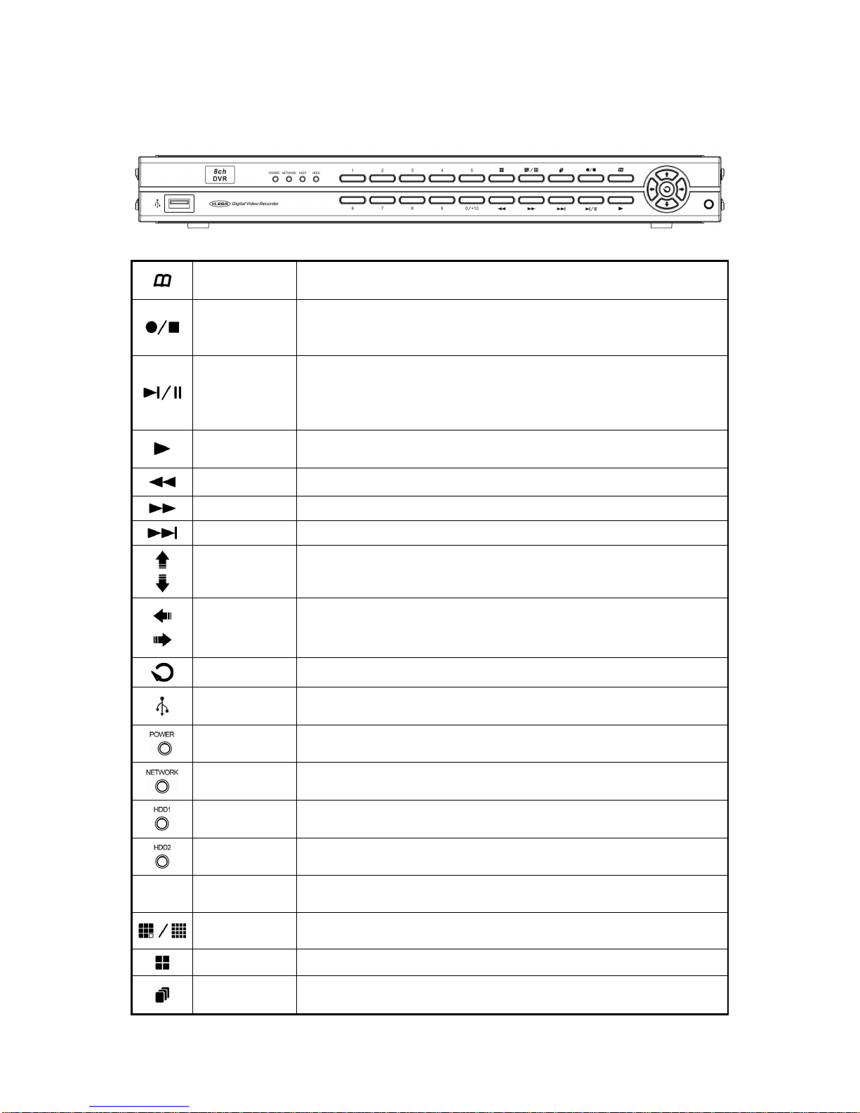
2. Front Panel...............................................................................................2
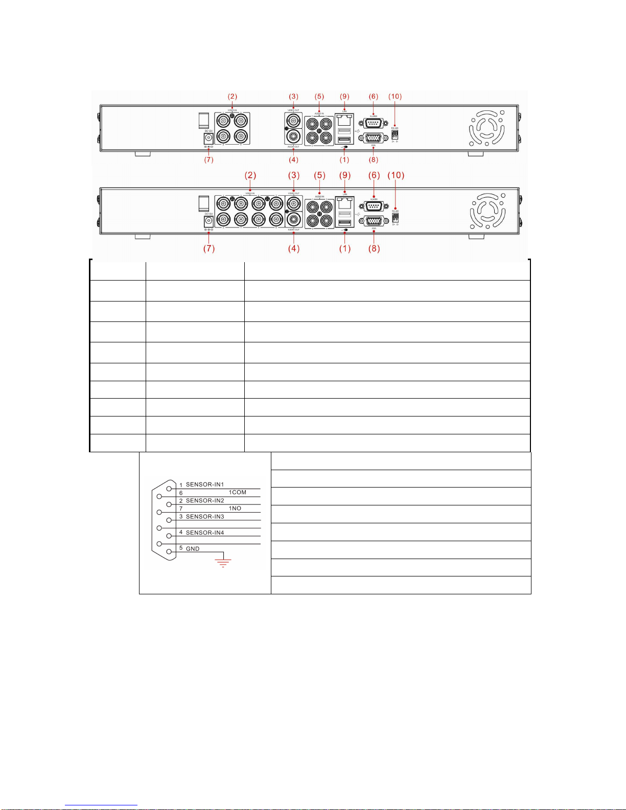
3. Installation ................................................................................................3
4. DVR Installation........................................................................................3
5. System Operation.....................................................................................4
6. Display Setup ...........................................................................................6
7. Search......................................................................................................8
8. Main Menu..............................................................................................10
8.1 Camera Setup................................................................................11
8.2 Record Setup.................................................................................13
8.3 Alarm Setup ...................................................................................14
8.4 Motion Detection............................................................................14
8.5 Network Setup................................................................................15
8.6 Log Search.....................................................................................17
8.7 Backup...........................................................................................18
8.8 System...........................................................................................19
8.8.1 Time Setting.........................................................................19
8.8.2 HDD Setup...........................................................................20
8.8.3 Display Setting.....................................................................21
8.8.4 System Information..............................................................22
8.8.5 User password.....................................................................22
8.8.6 System Language................................................................23
8.8.7 Audio setting ........................................................................23
8.8.8 System Maintenance............................................................23
9. Cell Phone Monitoring Operation............................................................24
10. H264Player Operation............................................................................27
11. Web Operation .......................................................................................29
12. Default Setting........................................................................................37
13. USB Flash Memory Stick Support List....................................................38

1
1. Specification
Video Format
NTSC PAL
Video Input
4 / 8 CH Input / BNC
Audio Input
4 CH Input / RCA
Video Output
1CH Output / BNC
Audio Output
1CH Output / RCA
XGA Output
800x600, 1024x768, 1280x1024, 1440x900
Alarm Input
4CH Alarm In
Alarm Output
Buzzer,1 x Relay Out (N.O、N.C)
Display Mode
Full Screen, 4/8CH Split Screen, Auto Switch, Picture in Picture
Display Resolution
720 x 480 720 x 576
Recording
Resolution
Highest
720 x 480 720 x 576
High
720 x 240 720 x 288
Normal
360 x 240 360 x 288
Recording Frame
Max. 120 / 240 FPS Max. 100 / 200 FPS
Compression Algorithm
H.264
Operating System
Embedded Linux
Pentaplex
Live / Record / Playback / Network / Mobile Phone
Recording Mode
Manual, Schedule, Event
Schedule Recording
Full Recording, Motion, Alarm, Manual Recording
Status Indicator
Power, Network, HDD1, HDD2
Event Mode Alarm Trigger, Motion Trigger, Video Loss
Recording Duration: 10~60 sec.
Playback Mode
Normal Speed: x1
Fast Forward: x2 / x4 / x8 / x16 /x32multiple speed
Slow Forward: 1/2, 1/4, 1/8 multiple speed
Fast Rewind: x2 / x4 / x8 / x16 /x32
Frame by Frame Playback: Forward
Search Function: Time / Event
Network Protocol
TCP/IP / PPPoE / DHCP / SMTP / DDNS
HDD Type
SATA3.5”HDD x 2 (No HDD Included)
HDD Management
Automatic Format System
PTZ Control
Communication Protocol (PELCO P, PELCO D, MIKAMI)
Backup Device
USB 2.0 Flash Memory Stick
Firmware Update
Host USB
Multi-Language
English / Chinese / Others
Control Mode
Front Panel / Remote Control / USB Mouse / Internet
Network Control
IE Browser
Network Function
Live Display / Playback / PTZ Control / System Setup
IR Extension
YES (Optional)
Power Supply
DC 12V / 4.16A(AC100V~240V 50/60HZ)
Unit Dimension
430mm (W) x 314mm (D)x 53mm (H)
Weight
2.83kg ( HDD and Power Adapter Not Included )
Operating Temperature
0℃~ 46℃

2
2. Front Panel
MENU
Under the live viewing mode, press MENU to enter the main menu.
Under the menu mode, press MENU to go to the upper menu.
Stop
Manual Record
Under the playback mode, press the STOP button to stop the operation
or go to the upper menu.
Press the Manual Record button to start recording under the live mode.
Pause
Step Forward
Under the playback mode, press the Pause button to pause the
playback.
Under the pause mode during the playback, press the button to
playback frame by frame in each time.
Play
Under the live viewing mode, press the Play button to enter the
playback mode.
Fast Rewind
Rewind speed: x2 / x4 / x8 / x16 / x32
Fast Forward
Forward speed: x2 / x4 / x8 / x16 / x32
Slow Forward
Slow Forward speed: 1/2, 1/4, 1/8
Up
Down
To move up or down of the selection setting in the menu.
Left
Right
To move left or right of the selection setting in the menu.
Enter
Press the Enter button to confirm the setup or go into sub-menu.
USB 2.0 Port
USB backup or firmware update.
(There are a front and a back USB that can be used one at a time.)
Power
Indicator LED The LED will light on when power on
Network
Indicator LED
The LED will light on when network connected.
HDD 1
Indicator LED
The LED will light on when the HDD 1 is written.
HDD 2
Indicator LED
The LED will light on when the HDD 2 is written.
1~8 Channel 1~8
Under the live viewing mode or playback mode, 1~8 Channel display.
8CH Split 8 channel split screen display.
Quad
Quad screen display.
Auto Switching
Under the live viewing mode, press the button to start/stop the auto
switching function.

3
3. Installation
1 USB Mouse Port 2.0 USB Mouse
2 Video In 8CH Video Input (BNC)
3 Video Out 1CH Video Output (BNC)
4 Audio Out 1CH Audio Output (RCA)
5 Audio In 4CH Audio Input
6 Alarm Alarm I/O
7 DC12V Power Input
8 XGA PC Monitor Output
9 LAN RJ-45 Network Connection
10 RS-485 For Speed Dome Use
Item
Point 1: CH1 sensor input.
Point 2: CH2 sensor input.
Point 3: CH3 sensor input.
Point 4: CH4 sensor input.
Point 5: ground.
Point 6: the first relay joint port.
Point 7: the first relay normal open.
4. DVR Installation
Connect the camera video output to the DVR video input port with BNC
connectors.
The camera install coaxial cable is suggested cat 6 or above.
DVR Network installation
Please connect DVR to HUB or router by using RJ-45 network cable and
make sure the DVR network indicator LED is on.
(Please refer to Network Setup for further network setting information of
using static IP, PPPoE or DHCP.

4
Alarm Installation
Please refer to Installation for external alarm I/O installation. Please refer to
Alarm Setup.
Speed Dome Installation
This device can support 3 kinds of communication protocol (Pelco D, Pelco P
& MIKAMI)
Power Installation
Please use the provided power cable and adaptor to connect the DVR
(AC100V~AC230V). Please refer to Installation for connecting position. The
DVR system will enter into live viewing mode when power is connected.
Please refer to Display Setup - Live Viewing Mode for more information.
5. System Operation
There are 3 kinds of DVR control method: front panel, remote control and USB
mouse.
USB Mouse Operation
1. Quick Menu: Right click the mouse button under the live viewing mode to
go for enter into Quick Menu.
2. Left click the mouse button under the main menu to go to the sub-select
menu.
3. Left click the mouse button under the select menu to go to the sub-menu.
4. Use the mouse to change the setting.
5. Please refer to Display Setup - PTZ Setup.
Remote Control Operation
Remote Control and front panel operation are the same; please refer to Front
Panel and the reference table of the button as below.
Stop
Record
Play
Fast
Rewind
Fast
Forward
Zoom
in/out
PTZ
Setup
Mute
Auto
Switch
Up
Selection
Left
Selection
MENU
Down
Selection
Split Windows display
Step/Pause
Slow Forward
PTZ IRIS
PTZ Focus
Search
Information
Enter
Right Selection
Cancel
Channel
1
~
8
Quad
Display

5
Virtual Keyboard Operation
The text input of the virtual keyboard is as below:
Menu Operation Front Panel & Remote
Control Operation Mouse Operation
Select character from virtual keyboard [Up/Down/Left/Right] [Move Cursor]
Keyin the select character [Enter] [Left Click]
Exit the virtual keyboard [MENU] [Left Click]out of selection area
Key Description of Virtual Keyboard
Delete the previous character
Switch to text input
Enter key. Save and exit the virtual keyboard
Other Keys Character Keyin
Main Menu Operation
Setup Operation Front Panel & Remote Control USB Mouse
Select [Up/Down/Left/Right] [Moving Cursor]
Enter Select Menu [Enter] [Left Click]
Return to Upper Menu [MENU] [Exit]
Setup Operation

6
Setup Operation Front Panel & Remote Control USB Mouse
Select [Up/Down/Left/Right] [Moving Cursor]
Confirm Select Setting [Enter] [Left Click]
Change the Select Setting [Left/Right] [Left Click]
Return to Upper Menu [MENU] Right Click
6. Display Setup
There are 3 kinds of screen display mode: Live, Auto Switching and PTZ. DVR.
Live Viewing Mode
The DVR will go to the live viewing mode after boot up. There are 5 different
status icon:
●: Record
M: Motion Triggered
L: Video Loss
A: Alarm Triggered
: Sound on/off
Setup Operation Front Panel&Remote Control USB Mouse
Channel 1~8 Single Channel
Display [CH1~8] Select one of channel
[Double click left button]
8 Channel Split Display [8 CH Split] Under single channel
[Double click left button]
Quick Menu [MENU] [Right]
Playback Mode [Play] [Right] QuickMenu
Start/Stop the Manual Record [Record] [Right] QuickMenu
Start/Stop the Auto Switching
Front Panel
[Auto Switch]
Remote Control
[Auto Switch]
[Right] QuickMenu
Start/Stop Mute Remote Control
[Mute] [Left] Left Click

7
Quick Menu
Setup Operation Front Panel & Remote Control USB Mouse
Select Item [Left/Right] [Moving Cursor]
Enter the Select Item [Up/Down] [Moving Cursor]
Confirm the Select Item [Enter] [Left Click]
Exit [MENU] [Left Click] out of selection area
PTZ
Please set the speed dome properly before control PTZ. Please refer to PTZ
Setup.
Setup Operation Front Panel & Remote Control USB Mouse
Select Item [Up/Down/Left/Right] [Moving Cursor]
Enter Select Item [Enter] [Left Click]
Zoom +,-
Focus, +-
Iris, +-
Adjust Movement Speed
PTZ Upward
PTZ downward
PTZ Left
PTZ Right
Start/Stop Auto Tracking
Exit [MENU] Right Click

8
Playback Operation
Setup Operation Front Panel & Remote Control USB Mouse
Fast Rewind [Fast Rewind]
Fast Forward [Fast Forward]
Step Forward [StepForward] |
Step/Pause [Step/Pause] |
Play 1x [Play]
Stop [Stop]
Digital Zoon Drag by Left Click
1~8Single Channel Display
[1~8 Channel] Select Channel [Double left click]
8split Display [8split] Under single channel [Double left
click]
Auto Switching
1. Auto switch starts from order CH1~CH8, 8 split channel.
2. Press the button again to stop the function.
7. Search
In Live mode, use Play button in the front panel/remote controller or right clicking the
mouse to switch to the Search function.

9
Setup Operation Front Panel & Remote
Controller USB Mouse
Search [Enter] [Left Click]
Select Channel [Up/Down] [Moving Cursor]
Select Dates [Up/Down/Left/Right] [Moving Cursor]
Playback [Enter] [Left Click]
Return to Upper Menu [MENU] [Right Click
No data: no color, data of alarm trigger: red color, normal record data: green
color.
Select the first half of hour frame under the date, the playback will start from
00 mins: 00 sec. Select the second half of hour frame under the date, the
playback will start from 30mins:00sec. If there is no data on the date, please
try to search from record list.
Select any of 8 channels to playback.
Record List

10
Setup Operation Front & Remote
Controller USB Mouse
Enter Select Item [Enter] [Left Click]
Select Item [Up/Down/Left/Right] [Moving Cursor]
Return to Upper Menu [MENU] [Left Click]
First Page
Previous Page
Next Page
Last Page
Mark all the events in this page
BackUp
List all of recording data and click on one of record data to
playback.
Backup
Please click “BACKUP” to backup the selecting file to USB memory
stick.
8. Main Menu
Setup Operation Front Panel & Remote
Controller USB Mouse
Select Item [Up/Down/Left/Right] [Moving Cursor]
Enter Select Item [Enter] [Left Click]
Exit Main Menu [MENU] [Right Click]

11
8.1 Camera Setup
Channel
Select one channel to set. Use CopyButton to copy present settings to other
channels.
Camera Title
Set the title of camera. Key in by using virtual keyboard.
Title Position
Set the title position. Set: Top Left, Top Right, Bottom Left, Bottom Right and
Off.
Display
Display the channel, set: On/Off
Camera Color Setup
Hue: 0~50
Brightness: 0~50
Contrast: 0~50
Saturation: 0~50
PTZ Setting

12
Type
Speed dome model type. Set: PTC-301, PTC-203ST, FUM 626,
JG_QG988, FUM 622SD, FUM 628 or off. Please select the correct
communication protocol if you enable this setting.
Protocol
Speed dome protocol. Set: PELCO P, PELCO D, MIKAMI or off.
Address
Speed dome address. Set: 0~255
Baud Rate
Speed dome baud rate. Set: 1200, 2400, 4800, 9600, 19200.
Tour Time
Speed dome tour time. Set: 5, 10, 15, 20, 25 sec or off.
Tilt Opposite
Set speed dome image upside down. Set: On/Off
Preset
Setup Operation Front Panel & Remote
Controller USB Mouse
Select Item [Up/Down/Left/Right] [Moving Cursor]
Enter Select Item [Enter] [Left Click]
Zoom +,-
Focus +,-
Iris +,-
Adjust Move Speed
Set PTZ Upward
Set PTZ Downward
Set PTZ Leftward
Set PTZ Rightward
Number Preset Setting
Save Preset Setting
Clear Preset Setting
Clear All Preset Setting
Return to Upper Menu [MENU] [Right Click]

13
Buzzer Duration
The buzzer ON duration when video loss.
Alarm Relay Duration
The Relay ON duration when video loss.
Time Display
Display the time in LIVE mode. Values: ON/OFF.
8.2 Record Setup
Channel Switch
On/Off the channel.
Resolution
NTSC Recording Resolution : 720x480, 720x240, 360x240.
PAL Recording Resolution: 720x576, 720x288, 360x288.
Frame Rate
Setting of Frame Rate: NTSC: 0-30 frames/sec; PAL: 0-25 frames/sec.
Quality
Setting of recording quality: Values 1-5. The bigger valve, the better quality.
Prerecord setting
Prerecording time when motion alarm. Values: 0-10 seconds.
Audio
On/Off the sound effects.
Encoding
Encoding of channel. Values: VBR or CBR.
Record schedule setup
Always and Schedule Record.
Record Schedule

14
Setup Operation Front Panel & Remote
Controller USB Mouse
Enter Select Item [Enter] [Left Click]
Select Channel [Up/Down] [Moving mouse wheel]
Select Time&Date [Up/Down/Left/Right] [Click/Drag-draw]
Return to Upper Menu [MENU] [Right Click]
Copy
(1) Select source (2) Select target (3) Press COPY icon to copy.
8.3 Alarm Setup
Channel
Select the channel to set. COPY icon can copy the present setting to other
channels.
Mode
Enable/disable alarm trigger. Set: On/Off.
Post REC
The duration of the recording after triggered: 10, 20,…, 60 sec. or off.
Buzzer Duration
The duration of the buzzer beeping after being triggered: 1~30 sec or off.
Alarm Duration
Alarm out after alarm triggered: 1~30 sec or off.
Event Display Duration
The Duration of single channel display after being triggered: 1~30 sec or off.
8.4 Motion Detection

15
Motion Detection
Select the channel to set. COPY icon can copy the present setting to other
channels.
Channel Status
Enable/disable motion detection for each camera. Set: On/Off
Sensitivity
Sensitivity level of motion detection. Set: 1~10. Higher value equal more
sensitive.
Motion Area Setup
Setup by each small square.
Setup Operation Front Panel & Remote Controller USB Mouse
Area Selection [Up/Down/Left/Right] [Moving Cursor]
Set Detection Area: must set
on none detection
area(Transparent Area)
(1)Move to the area
(2)Press Enter to set the area [Drag by Left Click]
Clear Detection Area: clear the
set detection area: must set on
detection area(Green Area)
(1)Move to the area
(2)Press Enter to set the area [Drag by Left Click]
Return to Upper Menu [MENU] [Right Click]
8.5 Network Setup

16
Mode
Set the connection method. Set: Static IP, DHCP, PPPoE.
Media port
Port used for stream media. Default is port 9000.
Webport
Port used for web access. Default is port 80.
Command Port
Port used for settings. Default is port 8000.
IPAddress
Assigned IP address.
Net mask
Assigned net mask
Gateway
Assigned gateway
PPPOE
Need account and password for PPPoE.
DDNS setting
DNS1 First Domain Name Server,Default : 168.95.1.1
DNS2 Second Domain Name Server, Default :168.95.192.1
DDNS
Enable/disable Dynamic Domain Name server. Values: On, Off.
DDNS Server
DDNS Server, Values: 3322, dyndns, cctvdvr.
When using DDNSserver, server name and account/password are
required.
E-Mail Setting
This manual suits for next models
2
Table of contents
Other VOLTA DVR manuals