VOLTDRIVE s.r.o.,
Háj 365 (MICOS TELCOM premises), 798 12 Kralice na Hané, Czech Republic
Tel.: +420 582 307 603, Fax: +420 582 307 688
5
Option: [2] Change settings
To change the items you can select the following options (their meaning is described above):
> Change:
[1] Circuit breaker capacity
[2] Number of chargers
[3] Source (packet)
[4] Tracked phases
[5] Safe region
[e] Exit
Selection :
These options enable setting the relevant values, supposing that the meaning of the numbers is as follows:
¬Option 1 : an integer between 1 and 99, unit – A.
¬Option 2 : an integer between 0 and 99, providing that 0 means that at least one charger is connected to the device,
i.e. the final number of chargers is “the entered number” + 1.
¬Option 3 : a character that will be entered into the sent packet.
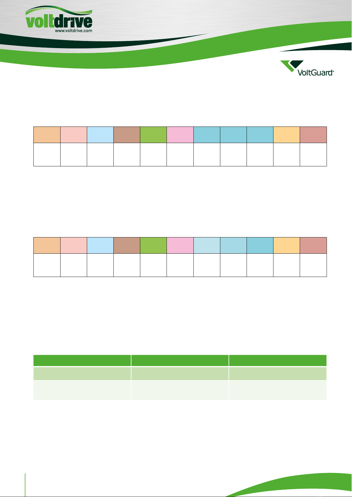
¬Option 4 : a number between 1 and 7 that determines the tracked phases. Binary encoded as follows:
∆4 = 100 first phase tracked
∆2 = 010 second phase tracked
∆1 = 001 third phase tracked
∆6 = 110 first and second phase tracked
∆3 = 011 second and third phase tracked
∆5 = 101 first and third phase tracked
∆7 = 111 all phases tracked
Option: [3] Save settings
The last option enables saving the master module setting to the internal memory. This setting is then loaded once the
power supply is on. The result of the option is either ok or fail. The result fail means the processor internal memory
error, i.e. the written data do not match the read data.
Selection :˙4
> saving ....
> ok.
----- Current Measurement Terminal -----
[1] Display settings
[2] Change settings
[3] Save settings
[4] Reload saved settings
Selection :
Option: [4] Reload saved settings
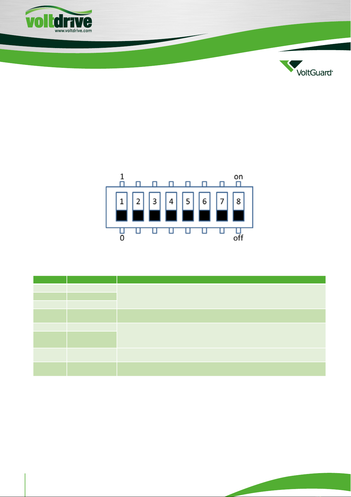
The console mode can be terminated in two ways, by:
¬Switching the DIP switch to the relevant position – the device will start using the changed setting values.
¬Selecting Option no. 4 – the setting stored in the FLASH memory is loaded before leaving the console mode.
CALIBRATION
The procedure for initiation of the calibration mode:
¬Turn on the device in the measuring mode (“DIP Start Calibration” jumper is open) – LED2 blinks slowly, the other LED
indicators are off.
¬Set the calibration current of 20A effective for all 3 phases (the easiest way is to use one calibration source serially
connected across all three inputs).
¬Connect the “DIP Start Calibration” jumper - LED2 blinks quickly, the other LED indicators are off.
¬Wait until LED4 is on – LED4 is on, LED2 blinks quickly, and simultaneously either LED2 is on (calibration result OK) or
LED5 is on (calibration completed with ERROR, the process needs to be repeated).
¬Open the “DIP Start Calibration” jumper – LED3 and LED4 turn off, LED5 and LED2 blink slowly