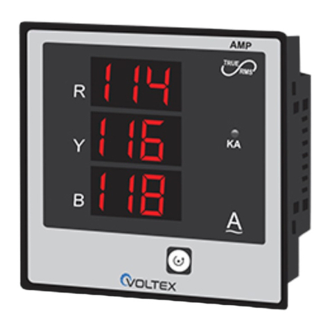
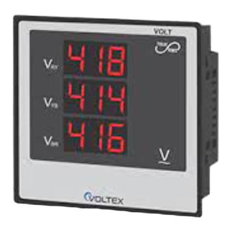
Voltex M380 User manual

1
M380, M380R, M320CT –Three Phase Meters Installation Manual
M380, M320CT-Three Phase Meters Installation Manual
Table of contents
1. Introduction.............…...........................................................................2
1.1 General ................................................................................................ 2
2. Product information......................................................................3
2.1 Meter parts.......................................................................................... 3
2.2 Technical Data ................................................................................... 4
3. Safety regulations ......................................................................... 7
4. Installation......................................................................................8
4.1 Protection requirements.....................................................................8
4.2 Mounting the meter............................................................................8
4.3 Connecting and commissioning the meter ....................................11
5. Functions ........................................................................................ 15
5.1. Reading and Control of the meter ................................................ 15
5.2. Operating LCD Display .....................................................................15
5.2.1. Bottom line information ................................................................. 15
5.2.2. Top line information........................................................................16
5.2.2.1. Display screens when power is ON............................................16
5.2.2.2. Auto-scrolling display screens ....................................................17
5.3. Test LED indicator ..............................................................................18
6. Maintenance instructions..........................................................19
7. Disconnecting meter..................................................................21

2
M380, M380R, M320CT –Three Phase Meters Installation Manual
M380, M320CT-Three Phase Meters Installation Manual
1.
Introduction
1.1.
General
M380, M320CT - Three-phase, low voltage 3x230(400)V, electronic meters enabling advanced
communicating capability for monitoring and managing the power network.
These meters measure active and reactive electric energy consumption and transmit data over
the power network, using two way Power Line Communication (PLC) to a central unit –
concentrator –from which data is transmitted to the billing center by cellular communication –
GSM/GPRS.
M380 –Direct connection meter.
M320CT - CT (current transformers) connection meter.
Fig. 1.1 Meter view

3
M380, M380R, M320CT –Three Phase Meters Installation Manual
M380, M320CT-Three Phase Meters Installation Manual
2. Product information
2. 1. Meter parts
Fig. 2.1 Meter front/side view
1
Hook
6
Terminal cover's screw and
sealing point
2
Upper cover
7
Terminalcover
3
LCD display(protected
bytransparent window)
8
IrDA port
4
Label
9
Red LED
5
Sealing points
10
Lower part of case

4
M380, M380R, M320CT –Three Phase Meters Installation Manual
M380, M320CT-Three Phase Meters Installation Manual
2.2. Technical Data
General
Nominal Voltage (Un)
3 x 230V AC
Supply Voltage range
80% - 115% Un
Nominal Frequency (fn)
50Hz
Consumption at Un
5 W –4.1 Var (Capacitive)
System connections
3 phase 4 wire
Measurement
Class Index
Active energy acc. to IEC62053-21
Class 2
Reactive energy acc. to IEC62053-23
Class 2
M380
Basic Current (Ib)
3x20A
Maximum continuous current (Imax)
3x80A
M320CT
Basic Current (Ib)
3x5A
Maximum continuous current (Imax)
3x20A
Environmental
Temperature range
operation
-10ºC to 55ºC
storage
-25ºC to 70ºC
Protection rating
IP51
Insulation Strength
Protective Class acc. to IEC62052-11
Class I I
Display
Type
LCD
Format
16 Characters x 2 Lines
Character size
9.55mm x 5.2mm
LED Indicator
Flash rate
200 imp/kWh
Communication Interfaces
PLC Frequency range
A-band 60-90 kHz
PLC Method
Spread FSK
Optical Comm. port IrDA baud rate
9600bps

5
M380, M380R, M320CT –Three Phase Meters Installation Manual
M380, M320CT-Three Phase Meters Installation Manual
Weight and Dimensions/ Case protection
Weight
1300 g
Width
145 mm
Height
228 mm
Depth
74 mm
Enclosure protection acc. IEC60529
IP51
Phase connections M380
Connection system type
Screw type terminals
Diameter
8.6mm
Maximum conductor cross-section
25 mm²
Minimum conductor cross-section
6 mm²
Screw dimension
M6x12
Screw head
Slotted,/comb. drive
Max. screw head diameter
< 8 mm
Tightening torque
<2.5 Nm
Phase connections M320CT
Current connections
Connection system type
Screw type terminals
Diameter
6 mm
Maximum conductor cross-section
6 mm²
Minimum conductor cross-section
4 mm²
Screw dimension
M4x8
Screw head
Slotted,/comb. drive
Max. screw head diameter
< 6.8 mm
Tightening torque
<1.5 Nm
Voltage inputs
Connection system type
Screw type terminals
Diameter
4.5 mm
Maximum conductor cross-section
1.5 mm²

6
M380, M380R, M320CT –Three Phase Meters Installation Manual
M380, M320CT-Three Phase Meters Installation Manual
Fig.2.2 Meter Dimensions

7
M380, M380R, M320CT –Three Phase Meters Installation Manual
M380, M320CT-Three Phase Meters Installation Manual
3.
Safety regulations
The following safety regulations must be observed at all times:
●
When installing or opening the meter the connections must be free of voltage.
Touching parts under voltage is life threatening. The relevant preliminary fuses should therefore
be removed and kept in a safe place until the work is completed, so that other persons cannot
replace them unnoticed.
●
Local safety regulations must be observed.
●
Installation of the meters must be performed by qualified industrial electricians only.
●
Meters which have fallen must not be installed, even if no damage is apparent,
but must be
returned for testing to the service or the manufacturer. Internal damage can result in functional
disorders or short circuits.
●
The meters must on no account be cleaned with water.

8
M380, M380R, M320CT –Three Phase Meters Installation Manual
M380, M320CT-Three Phase Meters Installation Manual
4.
Installation
Installation and commissioning must be performed by a qualified
industrial electricians only!
The persons installing the meter must be familiar with and observe the normal local safety regulations
and safety regulations specified in this “Installation Manual”.
The installer is responsible that the electricity meter is correctly and safely installed.
4.1.
Protection requirements
Circuit protection for electricity meter must be installed: fuse or circuit breaker with maximum switching
current less than maximal continuous current of the meter according to the technical specification.
4.2.
Mounting the meter
WARNING! The connecting wires at the place of installation must not be live when fitting the meter.
Touching live parts is dangerous to life. The corresponding preliminary fuses should therefore be
removed and kept in a safe place until work is completed, so that they cannot be replaced by anyone
unnoticed.
The meter should be mounted on the meter board or similar devices provided for this purpose. The
meter has one hook on the top backside of the meter's lower case and two mounting holes in the
terminal block, see Fig 4.1.
1. Determine the correct meter position for mounting the meter.
2. Set the meter hook in desired position and fix it by a screw .The hook on the meter's backside
can be moved up and down as shown on Fig 4.1.
3. Unscrew the meter terminal cover and remove it.
4. Shut off power to line. Make sure voltage is zero. Check with a phase tester or universal measuring
instrument whether the connecting wires are live. If so, remove the corresponding preliminary fuses and
keep them in a safe place until installation is completed, so that they cannot be replaced by anyone
unnoticed.
5. Make the three holes for fixing screws on the surface where the meter has to be installed. The
mounting dimensions are according with Fig 4.2.
6. Fit the meter with the three fixing screws on the mounting board :
1. First support the meter on the upper screw by the hook .
2. by using two screws, mount the meter through the bottom two holes in the meter's
terminal block on to the surface .

9
M380, M380R, M320CT –Three Phase Meters Installation Manual
M380, M320CT-Three Phase Meters Installation Manual
Fig.4.1 Meter Backside view

11
M380, M380R, M320CT –Three Phase Meters Installation Manual
M380, M320CT-Three Phase Meters Installation Manual
Fig.4.2. Drilling plan

12
M380, M380R, M320CT –Three Phase Meters Installation Manual
M380, M320CT-Three Phase Meters Installation Manual
4.3.
Connecting and commissioning the meter
WARNING! The connecting wires at the place of installation must not be live when fitting the
meter. Touching live parts is dangerous to life. The corresponding preliminary fuses should
therefore be removed and kept in a safe place until work is completed, so that they cannot be
replaced by anyone unnoticed.
The meters are ready to be installed as they are already calibrated and tested at
the factory.
1. Shut OFF power to line. Make sure voltage is zero. Check with a phase tester or universal
measuring instrument whether the connecting wires are live. If so,
remove the corresponding
preliminary fuses and keep them in a safe place until installation is completed, so that they cannot
be replaced by anyone unnoticed.
2. Remove the terminal cover to get easy access to terminal connections.
3. Shorten connecting wires to the required length and then strip them. If stranded wire is used, this
must be provided with ferrules for connection.
4. Connect the wires according to the diagram on the terminal cover and according to installation
diagram in this guide,see Fig. 4.3, 4.4 .Tighten the terminal screws firmly.
5. Make sure that the screws are tightened properly and the wires are not loose.
WARNING! Insufficiently tightened screws at the phase connections can lead to increased
power losses at the terminals and therefore to undesirable heating.
6. Check that the electricity meter is correctly wired and connected to specified voltage
3x230(400)V. Verify that the inputs and outputs of each phase are connected correctly. Make sure
each phase is connected to a phase and neutral to the neutral according to connection diagram
on the terminal cover.
7. Check that the input terminals are connected to a source of power after fuse or circuit-breaker
with rated switching current less than max current of the meter in order to provide circuit
protection.
8. Close the terminal block with terminal cover and fasten it by two screws. Seal with two seals in
order to prevent non-authorized access.

13
M380, M380R, M320CT –Three Phase Meters Installation Manual
M380, M320CT-Three Phase Meters Installation Manual
9. Insert preliminary fuses removed for installation. Turn ON power to line.
WARNING! Leaving the terminal covers open may cause a risk of touching the electrified terminals
which is life threatening. For any modifications to the installation therefore the preliminary fuses must
always be removed again and kept in a safe place until completion of work, so that they cannot be
replaced by anyone unnoticed.
10. Make sure the meter is activated and displays information. The red LED is ON or pulsing and the
LCD display screens are scrolling automatically every 2 second.
Check on the display whether all three phases L1, L2, L3 are indicated. If one phase is not present the
displayed voltage value of this phase will be 000 V or less than 090V.
Check if electricity is supplied to the customer. If the customer does not receive electricity, shut OFF power
to line and repeat steps 1, 6 -10.

14
M380, M380R, M320CT –Three Phase Meters Installation Manual
M380, M320CT-Three Phase Meters Installation Manual
Fig. 4.3. Terminal dimensions and connection diagram M380

16
M380, M380R, M320CT –Three Phase Meters Installation Manual
M380, M320CT-Three Phase Meters Installation Manual
15
Fig. 4.4. Terminal dimensions and connection diagram M320CT

16
M380, M380R, M320CT –Three Phase Meters Installation Manual
M380, M320CT-Three Phase Meters Installation Manual
5.
Functions
5.1.
Reading and Controlling of the meter.
The meters M380, M320CT measure electric energy consumption.
Control of the meter can
only be done remotely thru the concentrator.
5.2.
Operating LCD Display.
The electricity meter's data is displayed on it's LCD .
The screens scroll automatically every 2 seconds, without the intervention of the customer.
The LCD Display has 2 lines of 16 characters each.
5.2.1. Bottom line information
The bottom line scrolls long messages running from right to left, that are sent
from the AMI (
Advanced Metering Infrastructure) Control Center to the customer.
The messages can be sent to all customers –general message, or to a specific customer
individually - individual message.
If the message starts with three dots (…), it is an individual message sent only to this meter's display,
otherwise it is a general message sent to all the users.
5.2.2. Top line information
5.2.2.1. Display screens when power is ON

17
M380, M380R, M320CT –Three Phase Meters Installation Manual
M380, M320CT-Three Phase Meters Installation Manual
The Screens 1 - 6 appear in this sequence only once immediately when the meter is
turned ON.
Screen 1
100A 002171012
Program version
Screen 2
Soft.Ver. 11.22
Software version
Screen 3
Elec. #27100336
Electricity Meter ID
Screen 4
5. 000316.8kWh
Reading of Total (peak, of peak,
standard tariff) active accumulated
Power consumption, in kWh
Screen 5
6. 000025.0 kVarh
Reading of Total (peak, of peak,
standard tariff) reactive
accumulated Power consumption,
in kWh
Screen 6
7. 229V 227V 225V
The current measure of
Power Line Voltage in all three
phases L1, L2, L3

19
M380, M380R, M320CT –Three Phase Meters Installation Manual
M380, M320CT-Three Phase Meters Installation Manual
18
5.2.2.2. Auto-scrolling display screens
The following screens are continuously scrolling and changing every 2 seconds
Screen 7
24/10 13:15
Current Date and Time
(updated from Concentrator)
Screen 8
OfPk: 000144.0kWh
Reading of accumulated Power
consumption in Of Peak tariff,
in kWh.
Screen 9
Stnd: 000064.2kWh
Reading of accumulated
consumption in Standard tariff,
in kWh.
Screen 10
Peak: 000108.6kWh
Reading of accumulated
consumption in Peak tariff,
in kWh
Screen 11
06:00<Peak<20:00
TOU Duration:
The duration period of present
tariff is indicated in a special
message: HH:MM<NNNN<hh:mm
HH:MM –start time of current tariff
hh:mm –end time of current tariff
NNNN –current tariff name
Screen 12
Load Plugs OFF
In case an Appliance Control
Device (PLSWITCH) is installed in
order to control the load in the
customer's residence a screen will
display the status of the load plug:
ON/OFF

19
M380, M380R, M320CT –Three Phase Meters Installation Manual
M380, M320CT-Three Phase Meters Installation Manual
Screen 4
5. 000316.8kWh
Reading of Total (peak, of peak,
standard tariffs) active
accumulated Power consumption,
in kWh
5.3 Test LED indicator:
The red LED is placed under the front transparent window (see Fig. 2.1, position
9) and should be used for meter testing. The red LED indicates power consumption. While the meter
is on, its red light is visible and flashes at a rate depending on the power passing through the meter
relative to the pulse rate indicated on the label.
The Meter Constant (LED flash rate) as indicated on the label is 200 imp/kWh
Screen 5
6. 000025.0 kVarh
Reading of Total (peak, of peak,
standard tariffs) reactive
accumulated Power consumption,
in kVarh
Screen 6
7. 229V 227V 225V
The current measure of
Power Line Voltage in all three
phases L1, L2, L3

19
M380, M380R, M320CT –Three Phase Meters Installation Manual
M380, M320CT-Three Phase Meters Installation Manual
20
6.
Maintenance instructions:
The following points should be checked on the meters periodically:
●
The meter is in operation and serviceable.
●
All seals are undamaged
●
The condition of plastic around the terminals is undamaged
●
Wire isolation is undamaged
●
The meter is dry.
●
The plastic covers are clean and transparent
If the meter's transparent window is dirty and needs to be cleaned, use damp cleaning cloth to
remove the dirt.
WARNING! Make sure no liquid enters into the meter as this could damage the meter.
It should not be necessary to recalibrate the meter during its lifetime.
The meter's calibration is to be checked according to requirements of the Electricity Company.
If the meter does not operate correctly, the meter should be disconnected,
removed and sent to
the responsible service and repair center.

21
M380, M380R, M320CT –Three Phase Meters Installation Manual
M380, M320CT-Three Phase Meters Installation Manual
7.
Disconnectingmeter:
The meter should be removed as follows:
1. Turn OFF power to line.
2. Check that the connecting wires are not live using a phase tester or universal measuring
instrument. If they are live, remove the corresponding preliminary fuses and keep these in a
safe place until work is completed,
so that they cannot be replaced by anyone unnoticed.
3. Remove the two seals, unscrew plastic terminal cover and open it.
4. Check that the meter's terminals are not live using a phase tester or universal measuring
instrument. If they are live, repeat step 2.
3. Release the terminal screws of the connecting wires with a suitable screwdriver
and withdraw the connecting wires from the terminals.
4. Release three fixing screws and remove the meter.
5. Fit a substitute meter as described in Section 4 “Installation”.
The protection provided by the equipment may be impaired if the product is used in
a manner not specified in the Manual.
This manual suits for next models
2
Table of contents
Other Voltex Measuring Instrument manuals
Popular Measuring Instrument manuals by other brands

Circutor
Circutor DCB-72 mAdc instruction manual

GrainSense
GrainSense GS-ANLZR-A-2 quick start guide

AEA Technology
AEA Technology Liberator Series Operation manual

Renishaw
Renishaw PH10 PLUS Series Installation and user guide

Datalogic
Datalogic Smart-VS Quick reference guide

Jäger
Jäger ADwin-Pro System and hardware description

Boumatic
Boumatic StepMetrix Installation, Operation Maintenance & Service Instructions

Oval
Oval 50 instructions

PCB Piezotronics
PCB Piezotronics CS625B11 Installation and operating manual

brennenstuhl
brennenstuhl PM 231 operating instructions

Larson Davis
Larson Davis SoundAdvisor 831C Reference manual

GVS
GVS Archimedes A1200 quick guide