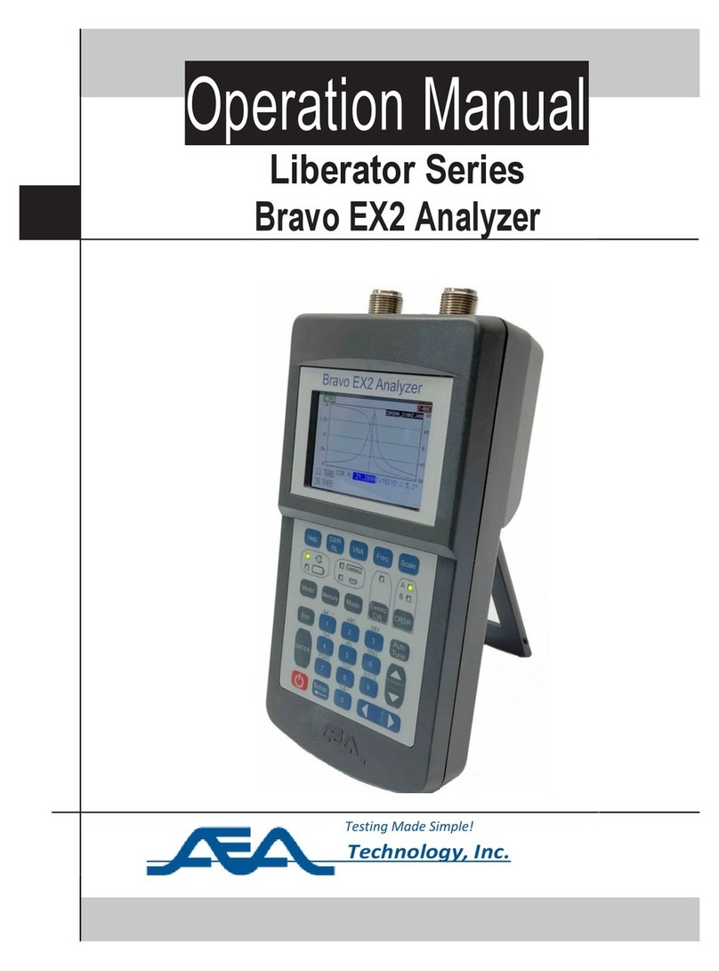
AEA Technology Liberator Series User manual

Operation Manual
Liberator Series
Bravo MRI 3000 Analyzer
Testing Made Simple!
_ Technology, Inc.

i
Proprietary Information
Reproduction, dissemination, or use of information contained herein for purposes other than
operation and/or maintenance is prohibited without the written authorization from AEA Technology,
Inc.
© 2021 by AEA Technology, Inc. All rights reserved. This document and all software or firmware
designed by AEA Technology, Inc. is copyrighted and may not be copied or altered in any way
without the written consent from AEA Technology, Inc.
The AEA Logos are trademarks of AEA Technology, Inc.
Acknowledgements:
Windows 7, Windows 10, and Power Point are registered trademarks of Microsoft Corp. WD-40 is
a registered trademark of WD-40 Company
409 cleaner is a registered trademark of Clorox Corporation
6055-3020 October, 2021

ii
WARNING
DC Port and A/C Adapter
Connecting and Operating the Analyzer while using the A/C or D/C adapters can create external
sparks during connection. Connecting or use of these power sources in an explosive atmosphere is
dangerous and should never be attempted. Always connect the MRI-3000 away from any explosive
atmosphere. Use ONLY internal battery power if the presence of explosive fumes is a potential
hazard.
Coax Test Ports
Thepresenceofanyvoltage,fromanappliedsourceorstaticbuild-uponcablesor antennas, particularly
vacant cables with no terminations or grounding, can cause an ignitionsparkwhentheyareconnected
tothe MRI Analyzer. Cautionshouldbetakento ensurecablesarefreeofanyvoltagesorstaticcharge
priortoconnectingtheinstrumentin a potentially explosiveatmosphere.
Operating Precautions
Although the Bravo MRI 3000 is a rugged instrument, care should be taken to avoid exposing it to
excessive external RF or a Magnetic Field. Do not connect the Bravo MRI to an active transmitter.
The Bravo MRI Should Not be allowed to get closer than 3 feet (1 meter) with a 1.5T Coil, and 5 feet
(1.5 meter) with a 3T Coil
The MRI Analyzer, when in its Belt Case, is splash resistant and designed to work for relatively long
periods in rain depending on intensity. It is not designed to be immersed in water. See Cleaning
Instructions in the appendix.
The Test Port is limited to +15dBm input power. Power exceeding this level could damage sensitive
input components.
Batteries
Due to the strong magnetic fields involved with MRI servicing, the use of batteries is not
recommended. Both the Bravo MRI unit and the MRI unit under test could be more susceptible to
damage if batteries were installed. for convenience we provide a 20 ft long DC extension cord to use
with the Ac adapter plug, if you must use batteries follow operating precautions instruction and keep
the analyzer a min of 3 feet (1 meter) away from the magnet
When batteries are required you can use Alkaline, NI-MH, LiION "AA" Batteries in the MRI Analyzer,
but when installed go to the Battery Menu and change the Battery Type to ALKALINE, Rechargeable
or NON.
Please note rechargeable batteries can't be charged inside the unit.
Cleaning
Under ordinary operating conditions, it should only be necessary to occasionally wipe the VIA Bravo
MRI with a soft, water moistened cloth. Avoid using solvents which may attack the plastic.

iii
Battery Precautions
Failure to carefully observe the following procedures and precautions can result in leakage of battery
fluid (electrolyte), heat generation, bursting, fire and serious personal injury.
Never dispose of batteries in a fire or heat them. Doing so may cause them to burst.
Do not connect the + (positive) and - (negative) terminals of batteries together with electrically
conductive materials, including lead wires.
Never disassemble batteries.
The + (positive) and - (negative) terminals of batteries are predetermined, observe polarity.
WARNING
1. Keep batteries or the equipment out of the reach of infants and small children.
2. Do not use batteries if the outer tube/label is scratched or damaged.
CAUTION
1. Do not use old and new batteries mixed together, or batteries at different charge levels. Do not
use Ni-MH batteries mixed together with a dry cell or other battery of a different capacity, type, or
brand name.
2. After they have been removed from equipment, store batteries in a dry place and within the
recommended storage temperature range.
Electrostatic Discharge (ESD) Precautions
The SWR Analyzer was constructed in an ESD protected environment. This is because most of the
semiconductor devices used in this instrument are susceptible to damage by static discharge.
Static charges are generated in numerous ways, such as simple contact, separation of materials, and
normal motions of persons working with the SWR Analyzer. To prevent instrument damage, practice
industry accepted techniques for handling static sensitive devices when using the SWR Analyzer. Very
often, coaxial cables and antennas also build up a static charge, which, if allowed to discharge by
connecting to the SWR Analyzer, may damage the instrument input circuitry. To avoid such damage, it is
recommended to dissipate any static charges by temporarily attaching a short to the cable or antenna
prior to attaching to the instrument.
If this instrument does become subject to ESD, be advised that the instrument may reset itself in this
event, and re-entry of the sweep parameters may be necessary.
The MRI Analyzer is designed to be safely operated in normal testing environments. Instrumentisnottobe
usedincriticalapplicationswherefailureof the instrument or inaccuracies in data might cause personal
injury or property damage. Use in such applications is not recommended
If you have any questions concerning the use of the MRI Analyzer or other AEA Technology, Inc.
instruments please contact us at:
Tel: 1-800-258-7805 or +1-760-931-8979 or Email: techsupport@aeatechnology.com

iv
MRI-3000 Literature Introduction
There are two literature items available for the MRI Analyzer:
Quick Start Guide is a laminated tri-fold held in the Belt Case’s inside pocket. This provides a light-
weight condensed guide to calibration, measurement functions and menus
Operator Manual instructional guide which has three purposes:
1. Gives a concise description of the instrument, keypad, menus and measurement
screens.
2. Provides user instructions in more detail than the Quick Start Guide including a section on
Measurement Information and Helpful Tips.
3. Provides specifications, troubleshooting guides, and accessories lists.
Both these items are available on line or the enclosed CD in PDF format ready for printing.
NOTES:
1.In addition to digital files of this literature the enclosed CD also contains MRI Analyzer PC
Vision™ software and a training Power Point presentation.
2.All these items and technical support is also available on our website: www.aeatechnology.com

v
Table of Contents
Proprietary Information.......................................................................................................................................... i
WARNING .............................................................................................................................................................. ii
DC Port and A/C Adapter................................................................................................................................ ii
Coax Test Ports............................................................................................................................................... ii
Operating Precautions..................................................................................................................................... ii
Batteries .......................................................................................................................................................... ii
Cleaning .......................................................................................................................................................... ii
Battery Precautions........................................................................................................................................ iii
Electrostatic Discharge (ESD) Precautions.................................................................................................... iii
MRI-3000 Literature Introduction ......................................................................................................................... iv
NOTES:.................................................................................................................................................. iv
MRI Analyzer Description ...................................................................................................................................... 1
General............................................................................................................................................................1
Instrument Front Panel Layout
............................................................................................................................ 2
Screen Layouts................................................................................................................................................2
General....................................................................................................................................................2
VNA Wide Format....................................................................................................................................2
VNA Narrow Format ................................................................................................................................4
SWR/RL Wide Format.............................................................................................................................4
SWR/RL Narrow Format..........................................................................................................................5
S21 Screen format...................................................................................................................................6
Keypad Operations
............................................................................................................................................... 6
Power ON/OFF
..............................................................................................................................................6
POWER ON.............................................................................................................................................6
NORMAL POWER DOWN......................................................................................................................6
HARD POWER DOWN ...........................................................................................................................7
Soft Reset........................................................................................................................................................7
Menu Keys
........................................................................................................................................................7
Function Keys
....................................................................................................................................................7
Help Key..................................................................................................................................................7
SWR/RL...................................................................................................................................................7
VNA Key..................................................................................................................................................7
FREQ Key ...............................................................................................................................................8
SCALE Key..............................................................................................................................................8
SWEEP/CW Key .....................................................................................................................................8
Menus
................................................................................................................................................................... 11
Menu Navigation............................................................................................................................................11
Meter Menu ...................................................................................................................................................11
BACKLIGHT..........................................................................................................................................11
COLOR SCHEME .................................................................................................................................11
KEYPAD BEEP .....................................................................................................................................12
BATTERY MENU ..................................................................................................................................12
DATE/TIME ...........................................................................................................................................12

vi
Mode Menu....................................................................................................................................................13
On a two-port MRI-3000, you will see this screen:................................................................................13
. 13
VNA MODE (Dual Port Models Only)....................................................................................................14
CALIBRATIONS....................................................................................................................................14
BROADBAND CAL................................................................................................................................14
SWEEP ENABLE ..................................................................................................................................14
GRAPH SELECT...................................................................................................................................14
GRID LINES..........................................................................................................................................14
MORE OPTIONS...................................................................................................................................15
OTHER OPTIONS Menu...............................................................................................................................15
RLC MODEL..........................................................................................................................................15
SYSTEM Z0...........................................................................................................................................15
RE-ENABLE SWEEP............................................................................................................................15
MEMORY OPERATIONS..............................................................................................................................15
DATA SAVE ..........................................................................................................................................15
DATA RECALL.....................................................................................................................................16
SAVE SETTINGS..................................................................................................................................16
RECALL SETTINGS..............................................................................................................................16
Measurement and Support Screens ..................................................................................................................... 16
General Information.......................................................................................................................................16
Measurement Screens ..................................................................................................................................17
SWR Screen..........................................................................................................................................17
Return Loss Screen...............................................................................................................................18
CW –Continuous Wave Screen............................................................................................................18
Cable Null Screens................................................................................................................................18
Calibration Sequence Screens..............................................................................................................19
MRI-3000 VNA Measurements ............................................................................................................................ 19
General Information.......................................................................................................................................19
S11 VNA SCREEN................................................................................................................................19
S21 VNA Screen (Two-Port Model only)...............................................................................................20
Calibration, Measurement Information and Helpful Tips ..................................................................................... 20
Calibration Processes....................................................................................................................................20
Broadband Calibration Process.............................................................................................................21
Frequency Specific Calibration Process................................................................................................21
SWR (Standing Wave Ratio a.k.a. Voltage Standing Wave Ratio-VSWR)...................................................23
Return Loss...................................................................................................................................................23
SWR and Return Loss Measurement Steps..................................................................................................24
MRI PC Vision™.................................................................................................................................................... 25
Abstract .........................................................................................................................................................25
Installing MRI PC Vision................................................................................................................................25
Running MRI PC Vision.................................................................................................................................25
Display Screen ......................................................................................................................................27
S11 Single-Port Operation.....................................................................................................................28
Graphs in Detail.....................................................................................................................................30
Z-Plot.....................................................................................................................................................31
Smith Chart............................................................................................................................................31

vii
Limit Lines .............................................................................................................................................32
S21 Operation (Two-port units only).....................................................................................................33
Naming Your Chart................................................................................................................................33
Saving Traces........................................................................................................................................34
Check Connection.................................................................................................................................34
Instrument File Management.................................................................................................................35
Warranty, Maintenance, and Troubleshooting Guides ........................................................................................ 37
Limited Warranty ...........................................................................................................................................37
Maintenance..................................................................................................................................................37
Battery Replacement Instructions..................................................................................................................37
Cleaning ........................................................................................................................................................38
Instrument Troubleshooting Guide................................................................................................................39
Factory Reset................................................................................................................................................39
Used to recover any program faults and then restores the factory defaults..................................................39
Appendix A .......................................................................................................................................................... 40
Specifications ................................................................................................................................................40
Appendix B .......................................................................................................................................................... 41
MRI Analyzer Model and Accessories...........................................................................................................41
Included items Part Number.........................................................41

1
MRI Analyzer Description
General
The MRI-3000 analyzer measures complex impedances of electrical components. In
particular, its design has been focused on making these measurements on the circuitry used in
MRI machines. The results of the measurements are displayed graphically, with some numeric
detail. You may choose to display the impedance from among several formats. The MRI-3000
sweeps across a range of frequencies, or operates at CW, either way the display is continuously
updated with new measurement results. This unit has many applications, including, but not
limited to:
1. Tune/align MRI coils (transmit and receive)
2. Measure Z, Phase Angle, Resistance, and/or Reactance of a load
3. Portable and economic replacement for network analyzer applications that measure S11.
4. Find resonant frequency and response curve
5. CW signal generator
6. Two plots may be simultaneously viewed on the same graph.
The MRI-3000 communicates with your PC via the MRI PC Vision™ application software allowing the
user to remotely control the instrument or view results on the PC's much larger display, in either X-Y or
Smith Chart plot format. The impedance altering effects of coax cable can be nulled out, so that the
load at the end of the coax is displayed. The MRI-3000 operates over a wide range of characteristic
impedances, so you are not limited to measuring 50 ohm systems.
Operator conveniences include: Non volatile storage, back lit display, display brightness adjustment,
versatile output displays, and USB port communications. Internal Batteries (8 AA batteries, not
included) power the MRI-3000 in situations where wall power is not available.

2
Instrument Front Panel Layout
Single Port Model Dual Port Model
Instrument Top Panel Layout
Screen Layouts
General
The MRI-3000 has two operating modes, VNA and SWR/RL. Each single-port mode has two
possible screen layouts, Wide and Narrow. Dual port mode (S21) is displayed in Wide only. This
gives a total of five possible screen layouts, which will be described here.
The MRI-3000's measurement screens are divided into two sections: The chart or graph section, and
the sidebar section. The Graph section is where the instruments measurements are graphically
represented by plots on a chart. This graph will display a different number of points depending on the
width selected. The sidebar section to the left of the chart, numerically indicates measurements at
center frequency. The size and content displayed also varies depending on the graph size selected.
The sidebar indications ALWAYS represent their respective measurements at center frequency (f0).
VNA Wide Format
Shown above is the VNA mode screen, in wide chart format. Features of interest are as follows:
Left & Right Scale indicators: These labels, in the upper corners of the chart area, indicate which
measurement that scale is for, and, more importantly, which trace is using that scale. The color of the
frame drawn around the label is always the same color as the trace using that scale.

3
Displayed Frequency Range:Displayed in the lower left of the screen, they indicate the frequency
endpoints actually displayed on the chart. The trace actually has points not visible on the chart, and
these can be viewed by enabling a cursor, and rolling the cursor past the left or right edge of the
chart, which will cause the graph to scroll left or right. This will also cause the frequencies displayed
to be updated as appropriate. When there are no cursors enabled, the upper frequency is displayed
near the lower right corner of the chart.
Cursor Frequency: For each cursor enabled, the cursor's frequency is displayed as shown. In the
above illustration, the cursor frequency is displayed highlighted-- indicating that it is selected, and can
be moved using the LEFT & RIGHT arrow buttons. As the cursor is moved, this frequency value is
updated.
Left & Right Scale Cursor Values: Immediately to the right of the cursor frequency, are the Scale
Cursor Values. These are the measurements for the frequency at which the cursor is positioned.
They are updated for every sweep.
It should be noted, that all of the above elements are common to both the VNA and SWR mode wide-
format screens. As previously mentioned, the MRI-3000's screen is composed of the chart area, and
the sidebar area (on the left side of the screen). In VNA mode, the sidebar in wide chart format is
made up of the following indicators (all of which represent their respective measurements at center
frequency):
Impedance Magnitude: Labeled "Z-Mag", this is the vector sum of the impedance's resistance and
reactance components. This value is in Ω.
Impedance Angle: Labeled "Z-Ang", this is the relative phase shift of the impedance, in degrees.
Resistance: Labeled "Rs" is the resistive component of the impedance, in Ω.
Reactance: Labeled "Xs" is the reactive (i.e. complex) component of the measured impedance, in Ω.
Reactance values can be positive or negative.
Capacitance / Inductance: Labeled "C/L", this indicator calculates the value of the equivalent series
or parallel reactive component to give the measured complex impedance. If the reactive part of the
impedance is negative, this value will be represented as a capacitance value. If it is positive, an
inductance value will be displayed. The RLC model used in the calculation can be selected from the
'OTHER OPTIONS' menu, on Page 15.

4
VNA Narrow Format
Shown above is the VNA mode presented in narrow chart format. In this mode, the chart is windowed
to 152 points visible. Note that the left and right scale indicators are still present, as well as the
cursor frequency, left and right scale cursor values displayed below the chart. As was the case in
wide chart format shown previously, moving the cursor past either edge of the chart will cause the
chart to scroll, revealing the data points that were previously not visible.
The sidebar now has fewer indicators, and the numerals for them are much larger-- enabling the user
to see them from a distance. The top indicator will always be the measurement for the left scale, at
center frequency. The trace color indicator (the triangle to the left of the indicator) gives the user a
visual cue as it will always be the same color as the trace that it belongs to.
The second indicator will always be the associated with the chart's right side scale, and the trace
color indicator will be the same color of that trace as well.
The third indicator will not always be present. This is the indicator for the value of 'Q' for the circuit
under test. In VNA mode, the 'Q' factor is displayed only when narrow chart format is selected
(shown here), and only if the impedance magnitude ('Z-MAG') is selected for either scale. The 'Q'
factor measurement will be explained in detail later in this document.
SWR/RL Wide Format
Shown above is screen of the MRI-3000 in SWR/RL mode, with wide chart format selected. This
appears similar to the screen in VNA mode, with some differences. In SWR/RL mode, only the left
scale is displayed, and only one trace is drawn on the chart. Only two measurements can be
selected to be plotted on the chart, SWR and RL (return loss). Pressing the SWR/RL key will cause
the displayed trace to switch between SWR and Return Loss.
The Sidebar to the left of the chart contains the following indicators, which will always be present for
this mode and chart format, and will always be the measurement at center frequency:
SWR: This indicator displays the Standing Wave Ratio measurement of the current trace at center
frequency.
Return Loss:Labeled 'RTL' this indicator is the measured return loss of the unit under test.
Impedance Magnitude: Labeled "MAG", this is the vector sum of the impedance's resistance and
reactance components. This value is in Ω, and is the same measurement as the one in VNA mode.

5
Impedance Angle: Labeled "PHASE", this is the relative phase shift of the impedance, in degrees.
It's the same as the equivalent in VNA mode.
SWR/RL Narrow Format
Shown above is the SWR mode presented in narrow chart format. In this mode, the chart is
windowed just as it is in VNA mode. Cursor operation is the same, with only the left scale displayed,
and selected by pressing the SWR/RL key.
Due to there being only two graph possibilities (SWR & RL), on this screen the top indicator will
always display the SWR at center frequency, the second indicator will always display the Return
Loss (again, at center frequency), and the third will always display the calculated 'Q' factor. The
displayed trace indicator (the triangle on the left) will always be the same color as the trace, but it will
move to point to the appropriate indicator whenever the SWR/RL key is pressed.

6
S21 Screen format
Shown above is the instrument's screen as it appears for Dual-port (S21) measurements. The left
scale will always be GAIN in dB, and the right scale will always be PHASE in degrees.
Keypad Operations
Power ON/OFF
The ON/OFF key is used to power the instrument on and off. There are different ON/
OFF sequences; Normal for starting with using the last settings at power down or Soft
Reset for starting with default settings. There are two different power down sequences
as described below the Power ON:
POWER ON –Press the ON/OFF key for one second.
A splash screen with AEA Technology’s logo and Version information will appear for several seconds.
It will then open to the test screen in use at the time it was normally or automatically powered down.
Keypad Power ON indication: LED lit
NORMAL POWER DOWN –From any Measurement screen, Press and hold the ON/ OFF key for
one second. Power Down sequence will start within one second later. This power down sequence
saves all the settings for resuming testing on the next Normal Power Onpress.

7
TheBATTERYSAVERAuto-PowerDownisanormalpower down which alsosaves all the settings.
HARD POWER DOWN –Press andhold theON/OFFkeyfortenseconds. Thisforces theMRI-
3000toshut downandshouldbeused if:
A. Theunitwillnotpowerdown withaNormalPowerDown (1secondholdofthe key).
B. IftheMRI-3000 isnotperformingcorrectly,menusorcursorkeysdonotwork,or themeasurement
screendoes notappearcorrectlyformatted.
NOTE: AHardPowerDownwillNOTsavethecurrentsettingsastheirdata/data corruptionmaybecausing
thefirmwareissue.IfaHardPowerDownneedstobe executedthenextpoweronshouldbetheSoftReset
proceduretoperformfirmware housekeeping and restore normal operation.
Soft Reset
With the MRI-3000 OFF, Press and hold the ENTER key
Press and release the ON/OFF key to power the MRI-3000 ON.
After power comes on... (~1 second) release the ENTER key
Display will allow you to confirm reset to factory default settings.
When Measurement Screen appears you can recall a saved setting or set desired settings
Menu Keys
These keys bring up the Meter Settings, Options settings, and Memory Operations menus, respectively.
For details, please refer to the Menus section, on page 11.
Function Keys
Help Key
The Help key has two modes of operation; First, if no function keys are active (CRSR,
FREQ, etc.) and no menus are open, pressing Help will open the help information for the displayed
Measurement Screen. This includes help with navigation in the screen and adjusting Frequency or Scale
ranges
.
Second, when a menu is open or a function key is active Context Sensitive Help will open and
provide instructions and options that address that particular open or highlighted menu item or function.
Using the Help key is a great tool for getting started, refreshing your memory on how things work.
SWR/RL
Press the SWR/RL key to directly access SWR & RL. Once there, pressing SWR/RL will alternate
between SWR and Return Loss modes. See section 3: Measurement Screens for information on
cycling modes, setup, and scales.
VNA Key
Press the VNA Key to access complex impedance measurements such as Z-Mag, Z-Angle. See section
3 Measurement Screens for information on cycling modes, setup, and scales.

8
FREQ Key Press the FREQ key to set frequency range of interest. There are two types of setting
screens for this operation:
Press FREQ once to enter START and END FREQUENCIES.
Press twice to enter CENTER FREQUENCY and SPAN.
Use the left/right arrow key to navigate digit positions, the alpha-numeric keypad to enter values, and
up/down arrow key to jump between upper and lower entries. Press ENTER key to save changes
and exit. If Broadband Calibration is selected it will go directly back to the Measurement Screen. If
Frequency Specific Calibration is selected it will exit to the Calibration procedure. See
Page 20
SCALE Key
The Scale key is used to cycle through preset vertical scales on the measurement screens.
SWR and RL have only one scale on the left side of the plot. Repeated presses will present
the next scale range in the cycle. See Section 3 Measurement screens for more information
on selecting and changing Scales.
SWEEP/CW Key
The Sweep/Continuous Wave key will switch the modes between them. The LED indicator flashes
when the instrument is sweeping the selected band or transmitting the center frequency.
Sweep is the normal mode performing frequency sweeps from low to high frequency
selected and measurements appear in graphic plots. Continuous Wave mode stops the
Sweep mode and only emits a continuous wave at the Center Frequency. This
changes the graphic plot to a list of tests showing digital value responses. The
Continuous Wave mode is useful when the antenna or other DUT is being tuned or
adjusted. In CW mode, measurements refresh at a faster rate than in Sweep mode.
See the Measurement Screens section on page 17 for information on setup and cycling through the
readings list. To exit Sweep/CW, press SWR/RL or VNA to enter those modes.
The CRSR (Cursor) key is used to activate Cursor A or both A & B Cursors with a second
press of the key. Cursors are controlled as follows:
A: Single cursor with data on screen. Cursor A LED lit. Use the left/ right arrow key to
move the cursor. Readings will automatically update to cursor’s position.
A & B: Press the CRSR key a second time to add the B cursor. Both A & B Cursor LEDs
will be lit.
Dual cursors will display on screen with cursors’ differential reading (CRSR ∆) below Cursor B. The
active cursor will be the last CRSR summoned with the CRSR key and the left/right arrow key will
control that cursor.
To alternate between the Cursors A & B to change which cursor is active, press the CRSR key as
needed. Exit cursors –Press the ESC key once to exit Cursor B only or reduce to Cursor A only and
twice to exit both cursors.
The Escape key has the following uses:

9
A. Exits menus or backs up one menu level saving any changes.
B. Exits the cursors as described above.
C. In HELP mode, ESC closes the on-screen HELP window and returns to either the Measurement
Screen or the menu or function where it was pressed to continue what you what
operation you were doing when HELP was pressed.
D. In Memory Save or Cable Null, Escape cancels the process prior to completion.
E. See on-screen prompts about using ESC to complete the current operation.
The ENTER key has the following uses:
In any measurement screen with a highlighted testing parameter, it will either cycle
through that parameter’s presets or exit to data entry screen like FREQ for example.
A. Saves alpha-numeric entries and moves to the next step.
B. In the Mode Menu the ENTER key activates the highlighted sub-menu.
The Auto Tune key works slightly differently in SWR/RL and in VNA mode, but in both
cases it only functions with one or both cursors enabled. In SWR and RL, pressing Auto
Tune will cause the selected cursor to seek to the LOWEST point on the graph. In VNA
Mode, the cursor will seek to the highest impedance point on the graph.
The up/down arrow key has the following uses:
In the menus it moves the menu selector to a desired item on the vertical menu list.
In the Memory Operations screen, it moves the file select highlight up or down one file
entry at a time.
In the measurement screens the UP arrow moves the highlight between scales or other
measurement parameters to make changes to that parameter.
In the date/time menu it is used to cycle through the day, month, year, or time settings.
The left/right arrow key has the following uses:
A. When in the measurement screen with cursors enabled, it moves the
active cursor left or right in the plot.
B. When in any alpha-numeric settings (FREQ, date/ time, Memory save,
etc.) it changes digit position for character entries.
C. In the menus it changes the options (horizontal menu) for highlighted
items in the vertical menu.
NOTE: See Page 11 for Menu Navigation.

10
A. The squared U above the 1 key is an underscore. Use as a space.
B. There are more than just the 3 special characters shown above the 0 key. Continued presses will
cycle through them on screen for selection.
C. Bcksp = Backspace to erase the character to the left of the entry cursor.
D. Bcksp key in the Memory menu will erase the saved test result or setting.
CAUTION –There is NO UNDELETE. Once a test result or setup is erased it is permanently deleted.
The alpha-numeric keypad
operates like those on smaller
cell phones. Press a selected key
once for entering the number and
repeat the key’s presses to cycle
to the character desired above
that key. In an alpha entry screen
the first press will present the first
alpha character above the
number. Subsequent presses will
cycle the alpha characters and
finally the number or use the Up
or Down arrow to cycle through
the entire characters set

11
Menus
Menu Navigation
Menus contain two types of lists; vertical list is the one you can see all items available and horizontal
lists that only show the selected item’s options; mode or value. The other horizontal selections are
hidden. Navigation is accomplished as follows:
1. Use the UP/DOWN arrow keys to select (highlight) the desired item in the vertical menu list
2. Then use the left/right arrow keys to change the highlighted item’s current setting and scroll
through the options. Some setting lists (horizontal menus) are as simple as ON or OFF options,
others are longer lists like the Color Schemes with 16 colors to choose from for each item on the
list.
3. Use the ENTER key as indicated to call a sub-menu of selections. Navigation in sub- menus
works the same.
4. When selections are completed, use the ESC key to save and exit the menu. Sub- menus, if any,
exit back to main menu and main menu exits back to measurement screen.
Meter Menu
The Meter Menu provides for control of the instrument itself. It has direct action items that
when highlighted and the left/right arrow key is pressed changes the current setting to the
next item in the horizontal menu.
The menu appears:
Below is a list of items and their options:
BACKLIGHT
LO, MED, HI Press to make a selection
(recommend MED for best light with less battery power consumption)
COLOR SCHEME
Selecting the 'COLOR SCHEME' menu item from the 'Meter' menu brings up this screen:
COLOR SCHEME: Press ENTER to open sub-menu:

12
This allows you to adjust the color of the various items on the MRI-3000's screen. When any item on
this menu is selected, you can use the (left and right arrow) buttons to select the color for
that item from a palette of 16 colors.
Color-settable items are:
TRACE A –This will be the color of the trace for the left scale.
TRACE B –Selects the color of the trace for the right scale.
CURSOR A –Set the color for the 1st cursor
CURSOR B –Sets color of the 2nd cursor
MENU TEXT -- This sets the color of all of the menus, all of the text items that appear on
measurement screens, as well as the color of the chart graticule.
BACKGROUND–Just what it says: The backdrop against which EVERYTHING is painted. Take care
that your background color has enough contrast against the menu text (set above).
Note: Menu Text and Background are linked so the same color can NOT be used for both. This
ensures that the instruments menus will always be visible.
KEYPAD BEEP
ON or OFF. Press to make a selection.
UNITS
FEET or METERS Press to make a selection
BATTERY MENU
Press ENTER to open sub-menu. Selecting the BATTERY MENU item from the 'Meter' menu will
bring up the battery settings screen:
There are only two settable items here:
BATTERY SAVER: Setting this option ON will cause the unit to automatically power down in 5
minutes after last key press. This is a normal power down and all modes, set-ups and calibrations are
saved and recalled on powering back up. This feature is not recommended when working with the
MRI PC Vision software. Auto power downs will interrupt communications between the PC and MRI-
3000.
BATTERY TYPE: When batteries are required you can use "AA" batteries of any type. This option
sets the type of battery used in the unit. The possibilities are NO BATTS, ALKALINE, or
RECHARGABLE. This selection is necessary as Rechargeable and non-rechargeable batteries are of
different voltages.
BATTERY STATUS: Cells total voltage and Current draw are displayed in mA.
DATE/TIME
Press ENTER to open sub-menu to set date/time (see below).
Press ESC to exit the Meter Menu.
Other manuals for Liberator Series
1
This manual suits for next models
1
Table of contents
Other AEA Technology Measuring Instrument manuals
Popular Measuring Instrument manuals by other brands
Extech Instruments
Extech Instruments 407727 user manual

Ellisys
Ellisys USB Explorer 350 user manual

IFM Electronic
IFM Electronic Efector 300 SI5002 operating instructions
Conrad
Conrad 67 25 06 operating instructions

PCB Piezotronics
PCB Piezotronics M357B14 Installation and operating manual
Kimo
Kimo AQ 110 user manual
Precision Gold
Precision Gold NO9AQ instruction manual

Kusam-meco
Kusam-meco KM 8041 Operation manual
X-Rite
X-Rite EyeOne Pro user guide
MICRO-EPSILON
MICRO-EPSILON capaNCDT 6630 instruction manual
Hanna Instruments
Hanna Instruments C 215 instruction manual

Pro-dig
Pro-dig Intelli-Tork H200 instruction manual
