In the event of an alarm condition, pressing the HUSH button
on the alarm unit will silence the alarm for approximately 10
minutes.
NOTE: Where multiple alarms are interconnected, the HUSH
function WILL NOT OPERATE EXCEPT ON THE UNIT THAT THE
ALARM WAS TRIGGERED FROM. The triggered unit can be
identified by the RED LED flashing.
Do Not Disturb Mode
When the unit indicates a low battery alarm or internal fault,
pushing the HUSH button will silence the alarm for 10 hours
and the red LED will flash every 40 seconds.
¬
The smoke alarm incorporates a replaceable battery
(CR17450) which is designed to power the smoke alarm
in the event of a short-term power outage. The battery is
designed to last 10 years subject to normal use and regular
maintenance from the date of manufacture and can be
replaced by opening the smoke alarm and accessing the
battery under the battery cover
¬Periodically apply the Test Procedure to test the alarm.
¬Smoke Alarm are prone to dust and insect ingress which can
cause false alarm, it is prudent to clean the smoke alarm
periodically. The Smoke Alarm must be kept clean so that
excess dust does not build up. Any insects or cobwebs in the
vicinity of the Smoke Alarm should be promptly removed.
Vacuum the outside of the Smoke Alarm to remove any dust
build up.
¬
Do not spray any cleaning liquids directly onto the smoke alarm.
Replace the battery
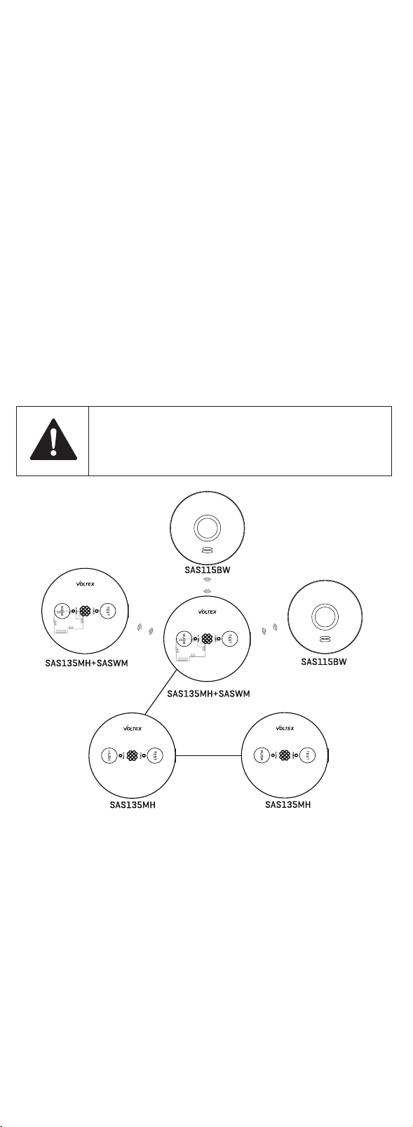
Audio and Visual Indication System Configuration
Trouble Shooting
Alarm Memory
Warranty Information
Maintenance
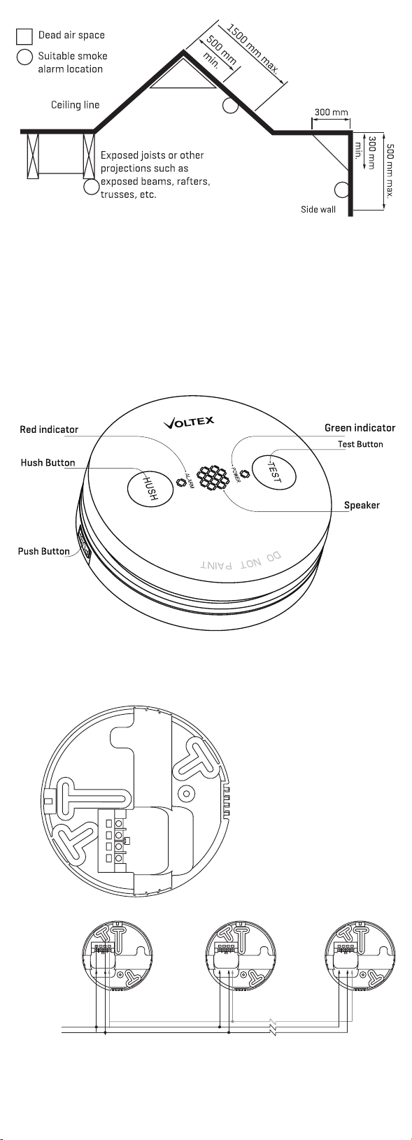
Test Procedures For Hardwired Interconnection
HUSH Mode
1. Ensure the green LED is continuously illuminated on each
unit, this indicates 240V mains AC power is available.
2.
Pressing and holding the test button on any smoke
alarm for at least 5 seconds will activate an alarm and
cause the red LED on the front face to flash.
(Note: all other interconnected smoke alarms will stop
alarming when releasing the Test button, but the red LED
will flash for 3 minutes.
3. Repeat this procedure for each alarm.
*Continuous alarm pattern: Beep 0.5s- Pause 0.5s- Beep
0.5s- Pause 0.5s-Beep 0.5s- Pause 1.5s repeatedly per ISO
8201 Smoke is detected, and the building must be vacated
immediately. Emergency services must be notified.
NOTE: If self-test fault warning is existing, but the product
can sound alarm when press the test button. The product can
continue to be used. Need to test weekly by press the test button
instead of self-test weekly.
Problem Solution
Green LED not lit Check mains power connection
Hard wire paired
smokes don't
alarm during test
Check if Smoke Alarms are in same
circuit, interconnect cable is corrected
firmly and mains power is connected.
Wireless
interconnected
smoke alarms
don't alarm
during test
Clean the wireless paired smoke alarm per
instruction and repair.
Alarms sound
for no apparent
reason
Check for fumes, steam, etc. from the
kitchen or bathroom. Paint and other
fumes can cause nuisance alarms. Check
for any sign of contamination such as
cobwebs or dust. Clean the alarm.
Press the local Hush button to silent the
Smoke Alarm triggered, identify the alarm
that triggered by the flashing red LED
(alarm will not silence if it does not have a
flashing red LED)
If cannot hush the smoke alarm, push
the button located on the side and open
the Smoke Alarm, take off the battery.
Contact Voltex.
Chirp every 40
seconds and
cannot hush
Check if battery has been installed firmly,
contact Voltex
Dust and insect
Contamination
Vacuum the outside of the Smoke Alarm
to remove any dust build up. Smoke Alarm
are prone to dust and insect ingress which
can cause false alarm, it is prudent to
clean the smoke alarm periodically.
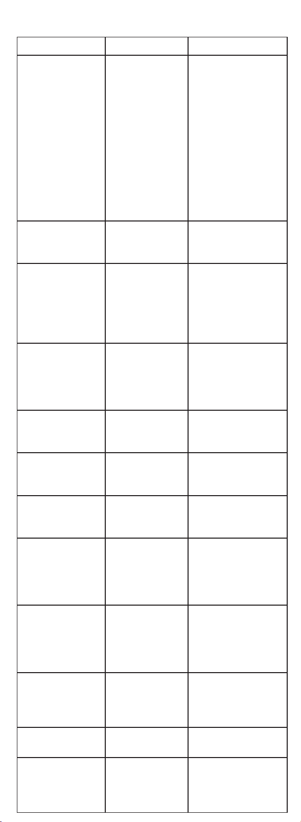
OPERATION MODE RED LED STATUS SOUND
Power Up Flash
No beep for
no wireless
interconnection.
No beep for
hard wired
interconnection.
Beep once when
wireless module is
installed & paired.
Beep 3 times when
wireless module is
installed but NOT
paired.
Alarm functioning
correctly
(standby)
Low intensity
flash every 40
seconds
-
Low battery
warning
Flash every 40
seconds
One chirp every 40
seconds.
Press HUSH button
enter ‘Do Not
Disturb’ Mode for 10
hours.
Fault warning Flash every 40
second
One chirp every
40 seconds. Press
HUSH button enter
‘Do Not Disturb’
Mode for 10 hours.
Self-test fault
warning
Flashes twice
every 40
seconds
-
HUSH mode
Flash once every
8 seconds for 10
min
-
Do not Disturb
Flash once very
40 seconds for
10 hours
-
Smoke detected
on local alarm*
Flash every
second
Continuous alarm
signal pattern,
Press HUSH button
to enter Silent Mode
for 10 min
Smoke detected
on interconnected
or paired unit
-
Continuous alarm
signal pattern,
Press HUSH button
to enter Silent Mode
for 10 min
Test function Flash every
second
Continuous alarm
signal pattern
until TEST button
released
Weekly self-test Flash once Chirps once every
week
End of Life (10
year) Warning
Flashes twice
every 40
seconds
Chips every 40
seconds
Cannot enter ‘Do
Not Disturb’ Mode.
Voltex warrants this accessory against defective workmanship
and faulty materials for seven (7) years from the original date of
purchase.
In an interconnected group, only the LED on the triggered alarm
flashes once approximately every 20 seconds for 72 hours. This
can be used to identify the triggered unit.
© Voltex Electrical 2020. All Rights Reserved.
CONFIG 1
Hardwire Interconnect Only, 1 Circuit
CONFIG 2
Hardwire & Wireless Interconnect, 1 Circuit
CONFIG 3
Wireless Interconnect Only, 2 Circuits
NOT ALLOWED