Volth ARGO HYTOS PVRM2X3-103 User manual

Operating instructions_PVRM2X3-103_15315_1en_09/2023
Page 1
www.argo-hytos.com
ARGO-HYTOS s.r.o.
Dělnická 1306, CZ 543 01 VRCHLABÍ
The following is the authorised translation of original operating instruction PVRM2X3-103 no. 15315_1cz_07/2023
issued by the producer:
PROPORTIONAL PRESSURE CONTROL VALVE,
REDUCING - RELIEVING, DIRECT-ACTING
DESIGNED FOR USE IN POTENTIALLY EXPLOSIVE ATMOSPHERES
PVRM2X3-103
OPERATING INSTRUCTIONS
TP
AEN
Important! Read the instructions before using the product.
Save the instructions for future reference.
If the operating instructions are lost, new ones can be found on the ARGO-HYTOS website www.argo-hytos.com

Operating instructions_PVRM2X3-103_15315_1en_09/2023
Page 2 www.argo-hytos.com
PROHLÁŠENÍ O SHODĚ
ARGO
-HYTOS
o
I
Typ I Type I Typ Cís/o I No. I N Vydán I lssued I Ausgestellt

Operating instructions_PVRM2X3-103_15315_1en_09/2023
Page 3
www.argo-hytos.com

Operating instructions_PVRM2X3-103_15315_1en_09/2023
Page 4 www.argo-hytos.com

Operating instructions_PVRM2X3-103_15315_1en_09/2023
Page 5
www.argo-hytos.com
UK DECLARATION OF CONFORMITY
ARGO
-HYTOS
Dělnická 1306, 543 15 Vrchlabí, Czech Republic
o co, s
�
°°° °
D
1

Operating instructions_PVRM2X3-103_15315_1en_09/2023
Page 6 www.argo-hytos.com

Operating instructions_PVRM2X3-103_15315_1en_09/2023
Page 7
www.argo-hytos.com
Contents of operating instructions
Chapter Page
Declaration of conformity 2
Overview of signal words and warning signs used in the text 8
Overview of the symbols and signs used in the text 8
Glossary of technical terms used 8
1. Use of the product 8
2. Valve protection against intitiation of explosion in explosive atmospheres 9
2.1 Protection of electrical parts 9
2.2 Cable gland 9
2.3 Protection of non-electrical parts 10
2.4 Applicable legislation and standards 10
3. Risks and limitations of product use 10
3.1 Risks associated with operating in explosive atmospheres 10
3.2 Risks associated with the hydraulic part of the valve 11
3.3 Risks associated with the electrical part of the valve 11
4. Product description 11
4.1 Materials used 12
4.2 Surface protection against corrosion 12
4.3 Basic technical parameters 12
4.4 Working fluid 13
4.5 Valve characteristics 13
4.6 Legislation and standards 13
5. Product modifications 14
6. Target group of users 14
7. Operating instructons broken down into product life stages 14
7.1 Transport and storage of the product 14
7.2 Installation of the product 14
7.2.1 Electrical connection of coils 15
7.2.2 Connecting the valve to the hydraulic circuit 17
7.3 Commissioning 18
7.4 Normal operation 19
7.5 Extraordinary and emergency situations 19
7.6 Repairs carried out by specialist 20
7.6.1 Replacing a faulty valve 20
7.6.2 Replacing the sealing rings at the base of the valve body 20
7.7 Product maintenance 21
7.8 Spare parts supplied 21
7.9 Product disposal 21
8. Manufacturer contact 21
Mandatory traceability
Related documents:
Ex-coil EX18 user manual (Original document B18 of the coil manufacturer, SCHIENLE)
Product catalogue: Screw-in proporcional pressure reducing - relieving, Direct-Acting valve PVRM2X3-103 (no. 5315)
Datasheet: General Technical Information GI (no. 0060)
Spare parts catalogue SP (no. 8010)
Datasheet: Tools for machining chambers for screw-in valves (SMT no. 0019)
1. Based on legislative requirements, all operators in the logistics chain, from the manufacturer of the certified Ex solenoid coil to the end user
of the complete equipement, are obliged to make and maintain traceability records of Ex products, enabling, if necessary, the withdrawal
of products of certain serial numbers from the market due to defects of non-conformities, endangering safety of use in an explosive
atmosphere. In practice, this means keeping records of the assignment of Ex coil/valve identification numbers to the identification numbers
of the operators immediately down the logistics chain.
2. To meet the requirement for traceability of Ex products, it is necessary to keep product type labels legible throughout their technical life.

Operating instructions_PVRM2X3-103_15315_1en_09/2023
Page 8 www.argo-hytos.com
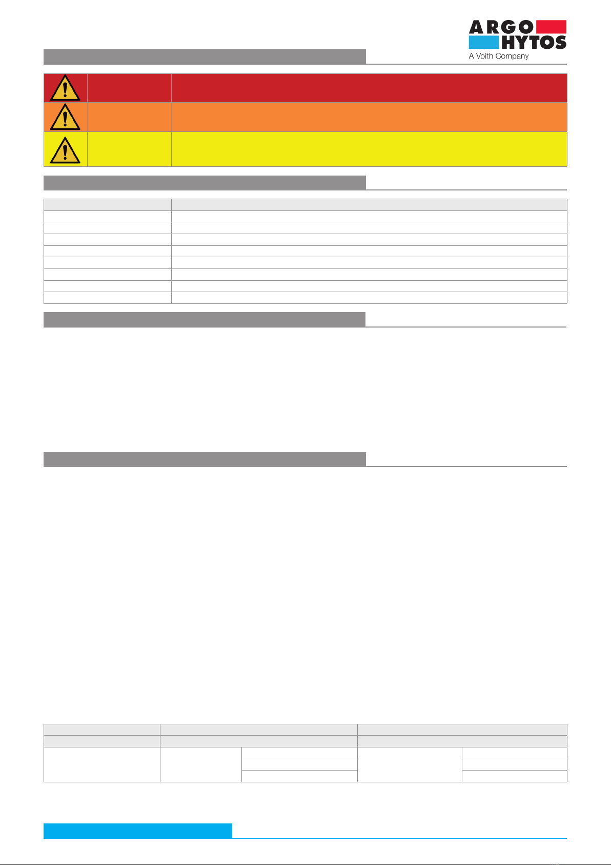
An overview of signal words and warning signs used in the text
An overview of other symbols and abbreviations used in the text
Symbol, designation Description of the meaning of the symbol, designation
AC, DC Designation for alternating (AC) and direct (DC) current, voltage
ATEX Explosive Atmospheres
EPL Equipment Protection Level (see EN 60079.0)
IEC International Electrotechnical Commission
NBR Rubber used for the manufacture of seals
PA Polyamide
PE Polyethylene
PU Polyurethane
Glossary of technical terms used
›A hydraulic mechanism is one in which energy is transmitted via the pressure energy of the working fluid.
›The volumetric flow rate Q is the amount of liquid in volume units that flows through a given flow cross-section per time unit
(SI unit is m3s-1, in practice the unit l/min is used)
›The control solenoid is designed to reposition the valve spool that interconnects or closes the channels in the body. The solenoid consists of
an excitation coil which, by passing an electric current through the winding, generates a magnetic field which exerts a force on the armature of
the mechanical actuating system.
›The pressure reducing valve is a valve designed to control pressure. It reduces the input pressure to a set value and keeps the output pressure
constant. In addition, the three-way version, protects the output branch of the hydraulic circuit, usually leading to the appliance, against overpressure.
›The screw-in valve is designed to be screwed into a shaped chamber in the hydraulic block. The valve body is replaced by a steel sleeve in
which the spool or poppet moves.
›Pressure is the force acting per area unit (SI unit Pascal (1 Pa = Nm-2), in practice the unit used is bar (1bar = 0,1MPa)
1. Use of product
The PVRM2X3-103 hydraulic valve is a proportional pressure reducing valve, directly controlled by a solenoid. The valve is designed to be screwed
into a shaped cavity in a block with metric connection thread M24x1,5. The shape and dimensions of the cavity comply with the technical standard
ISO 7789. When flowing towards the appliance (port A), the pressure reducing valve reduces the value of the input pressure from the source-pump
(channel P) to the set value of the output pressure and keeps it constant. The value of the reduced pressure is adjusted by a solenoid in proportion to
the control current signal through the solenoid. If the appliance is overloaded with pressure, for example by an excessive external force, the valve
closes the pressure input from the pump and relieves the appliance branch by connecting it to the tank (port T)
Valves with ATEX certification according to Directive 2014/34/EU and IECEx certification according to IECEx OD 009 and related harmonized
standards may be used in explosive atmospheres consisting of mine gas, gas or dust. The valves are marked with the CE Ex mark of conformity and
are accompanied by a Declaration of Conformity.
Use in explosive atmospheres:
Equipment - group I, mines, where the explosive atmosphere of firedamp consists predominantly methane.
The valve has a high level of safety (EPL = Mb), which makes initiation unlikely during the interval between gas discharge and valve shutdown.
It is designed for category M2 devices that remain off after gas discharge.
Equipment - group II, where the explosive atmosphere consists of gasses other than mines gas.
The valve has a high level of safety (EPL = Gb) which allows the valve to be used in zones 1 and 2. The valve must not be used in zone 0.
There is a risk of explosion. The valve is certified for gas groups IIA (typical gas is propane), IIB (typical gas is ethylene) also for hydrogen from group IIC.
The joint dimensions do not meet the requirements for Group IIC acetylene.
Equipment - group III, where the explosive atmosphere consists of dust and flammable flying particles.
The valve has a high level of safety (EPL = Db) which allows the valve to be used in zones 21 and 22. The valve must not be used in zone 20. There is
a risk of explosion. The valve is certified for all dust groups - IIIA (flammable flying particles), IIIB (non-conductive dust) and lIIC (conductive dust).
Area of application
Equipment - group I – MINES Equipment - group II (IIG) - GAS Equipment - group III (IID) - DUST
Category M1– NO Zone 0 - NO Zone 20 - NO
Categorie M2
(the device remains
switched off)
Zone 1
Zone 2
IIA (propane) Zone 21
Zone 22
IIIA (flammable particles)
IIB (ethylene) + H2 (hydrogen) IIIB (non-conductive dust)
IIIC (conductive dust)
DANGER Signal word combined with a warning sign used to signify that a dangerous situation which could result in
death or serious injury is imminent.
WARNING Signal word combined with a warning sign used to signify the occurrence of a potentially dangerous situation
that could result in death or serious injury if not avoided.
CAUTION Signal word combined with a warning sign used to signify a potentially hazardous situation which, if not
avoided, may result in minor or moderate injury.

Operating instructions_PVRM2X3-103_15315_1en_09/2023
Page 9
www.argo-hytos.com
Temperature class
The valves are only supplied with a coil nominal input power of 18 W for functional reasons.
The surface temperature of the coil meets the conditions of class T4 with a maximum surface temperature of 135 °C.
The use of the valve in the temperature class is subject to the maximum supply voltage of the coil not being exceeded, the working
fluid temperature and the ambient temperature not being exceeded (see Table 4.4 Basic technical parameters).
2. Valve protection against intitiation of explosion in explosive atmospheres
2.1 Protection of electrical parts
The electrical part of the valve is an ATEX and IECEx certified solenoid coil. The basic is the „d“ protection by flameproof enclosure (EN 60079-1, IEC
60079-1), which prevents the penetration of hot gases into the surrounding explosive atmosphere in the event that an explosion is initiated inside the
flameproof enclosure. For explosive atmospheres consisting of dust, the enclosure „t“ (EN 60079-31, IEC 60079-31) is used. In addition, the coil is
sealed with a potting compound.
Certification across standards NEC 500 and NEC 505, 506
NEC 500 (USA), Annex J (Canada) NEC 505, 506 (USA) CEC Section 18 (Canada)
Class I Division 1 Group B, C, D T4 Cl 1 Zone 1, AEx db IIB+H2 T4 Ex db IIB+H2 T4 Gb
Class II/III Division 1 Group E, F, G T4 Zone 21, AEx tb IIIC T135°C Db Ex tb IIIC T135°C Db
I M2 Ex db I Mb
II 2G Ex db IIB + H2 T4 Gb
II 2D Ex tb IIIC T135°C Db
Certification ATEX, IECEx and UKCA
Use of the valve in potentially explosive atmospheres
2.2 Cable gland
The cable gland is a separately certified ex-component. A gland with certified type protection „d“ must be used to prevent hot gases from escaping
and initiating an explosion in the surrounding environment in the event of an explosion in the interior of the coil casing. (The gland is not included
with the valve.)
I M2 Ex db I Mb
II 2G Ex db IIC Gb
II 2D Ex tb IIIC Db
Certification Number Issued Certification body
EU-Type Examination Certificate FM23ATEX0008X 13.6.2023 FM Approvals Europe Ltd. (Notified body No. 6024)
One Georges Quay Plaza, Dublin, Ireland D02 E440
IECEx Certificate of Conformity IECEx FMG 23.0003X 12.6.2023 FM Approvals LLC
1151 Boston-Providence Turnpike, Norwood, MA 02062, USA
UK-Type Examination Certificate FM23UKEX0010X 16.6.2023 FM Approvals Ltd. (Approved body No. 1725)
Voyager Place, Maidenhead, Berkshire, SL6 2PJ, UK
Group Description Corresponds to EPL
Group B A typical gas is hydrogen Gb
Group C The typical gas is ethylene Gb
Group D Typical gases are methane and propane Gb
Group E Conductive dust Db
Group F Coal dust Db
Group G Non-conductive dust, grain dust Db
Class III Flammable airborne particles, paper or cotton processing Db
Certificate Number Issued Certification body
Certificate of Conformity FM23US0009X 12.6.2023 FM Approvals LLC
1151 Boston-Providence Turnpike, Norwood, MA 02062, USA
Certificate of Conformity FM23CA0005X 12.6.2023 FM Approvals LLC
1151 Boston-Providence Turnpike, Norwood, MA 02062, USA

Operating instructions_PVRM2X3-103_15315_1en_09/2023
Page 10 www.argo-hytos.com
2.3 Protection of non-electrical parts
2.4 Applicable legislation and standards
The non-electrical part of the valve consists of the hydraulic part and the solenoid actuating system.
The safety of the non-electrical parts has been ensured and assessed according to ISO 80079-36, ISO 80079-37 and EN ISO/IEC 80079-38.
› The moving parts, the spool/cone, armature and pin of the control system, perform a sliding motion in a space separated by a seal from
the surrounding environment and flooded with working fluid.
› Not exceeding the maximum surface temperature of the given temperature class is conditioned by not exceeding the maximum temperature
of the working fluid (70 °C), the maximum ambient temperature (see table 4.4 Basic technical parameters) and the nominal voltage of the coil.
› The valve body and coil body are of robust construction, sufficiently resistant to destruction by mechanical shock.
(Valve body impact resistance test performed according to EN IEC 60079-0 paragraph 26.4.2: two impacts with a weight with a hardened head of
diameter D25 mm, weighing m = 1 kg, falling from a height of 0.7 m, with a total potential energy of 7 J)
› The hydraulic section has sufficient compressive strength, tested at 1.5 times the maximum operating pressure of the fluid.
› The surface of the valve is grounded using a grounding screw and protected against static electricity discharge.
› The construction materials used meet the requirements for limited content of certain elements to prevent the formation of electrical cells and
excessive corrosion.
› The surface materials used do not create sparks during mechanical impacts.
Non-electrical part
of the valve
I M2 Ex h I Mb
II 2G Ex h IIC T4 Gb
II 2D Ex h IIIC T135°C Db
The valve complies with the relevant requirements of legislation and standards:
Directive 2014/34/EU (harmonized NV 116/2016) Equipment for potentially explosive atmospheres (ATEX)
IECEx OD 009 Operational Document
Standards used to assess the conformity of the electrical parts:
CENELEC EN IEC 60079-0
Explosive atmospheres – Part 0: Equipment – General requirements
EN 60079-1, IEC 60079-1
Explosive atmospheres – Part 1: Equipment protection by flameproof enclosure „d“
EN 60079-31, IEC 60079-31
Explosive atmospheres – Part 31: Equipment dust ignition protection by enclosure „t“
Standards used to assess the conformity of the non-electrical parts:
EN ISO 1127-1
Explosive atmospheres – Explosion prevention and protection – Part 1: Basic concepts and methodology
EN ISO 80079-36
Explosive atmospheres – Part 36: Non-electrical equipment for explosive atmospheres – Basic method and requirement
EN ISO 80079-37
Explosive atmospheres – Part 37: Non-electrical equipment for explosive atmospheres – Non-electrical type of protection constructional safety „c“,
control of ignition sources „b“. liquid immersion „k“
EN ISO/IEC 80079-38
Explosive atmospheres – Part 38: Equipment and components in explosive atmospheres in underground mines
3. Risks and limitations of product use
3.1 Risks associated with operating in explosive atmospheres
DANGER
Explosive atmosphere type and zone
The valve must not be used outside the specified range (see paragraph 1Product use ), in particular it is not
intended for equipment category M1group l (mines) zone 0 group II (gases) and zone 20 group III (dust).
Risk of explosion.
DANGER
Surface temperature
When selecting the valve, the surface temperature requirement of the valve must be taken into account.
It must be min. 25 °C lower than the temperature necessary to initiate an explosion of an explosive
atmosphere of a given composition. If the initiation temperature is exceeded an explosion will occur.
DANGER
Handling in an explosive atmosphere
It is forbidden to install, disassemble, repair or replace the valve in an exlosive atmosphere.
Risk of explosion.

Operating instructions_PVRM2X3-103_15315_1en_09/2023
Page 11
www.argo-hytos.com
DANGER
Maximum operating pressure
The valves may be used for a maximum input working fluid pressure of 90 / 50 bar (see 4.3 Basic technical
parameters). If the maximum pressure is exceeded, there is a risk of unreliable valve operation and damage to
the valve.
WARNING
Valve installation
The valve may only be installed in the corresponding cavity. The seals must not be damaged. The valve must be
tightened to the specified tightening torque of 20+5 Nm. Otherwise, there is a risk of leakage of the working
fluid and pressure release of the valve. (For details see paragraph 7.2 Product installation)
CAUTION
Maximum operating temperature
The maximum operating temperature must not exceed the temperature range allowed in paragraph 4.3 Basic
technical parameters or in the datasheet. Both the temperature of the operating fluid and the ambient tempera-
ture significantly influence:
a) the surface temperature of the valve
b) the temperature of the solenoid coil winding - there is a risk of a reduction in hydraulic performance
c) the seal material - risk of seal damage and leakage of the working fluid.
CAUTIONÍ
Surface temperature of the valve
The surface temperature of the valve can exceed 100 °C due to the temperature of the working fluid and
pressure loss in the valve being converted to heat. Do not touch the surface of the valve when the circuit is
operational, even after switching off. Wait until it has cooled down to a safe temperature.
There is a risk of burns.
CAUTION
Working fluids used
Valves may only be used for normal working fluids, especially hydraulic oils (see chapter 4. Product description).
It is forbidden to use the following as working fluids, in particular:
› water and aquesous solutions that will cause corrosion and loss of valve function
› liquids which are flammable or explosive, the heating of which may cause fire or explosion when
passing through the valve
› aggresive liquids (e.g. acids and hydroxides) which will cause damage to the valve and loss of
function.
The flash point of the used working fluid must be at least 50 K higher than the maximum allowed of surface
temperature of the valve in the given temperature class.
3.2 Risk associated with the hydraulic part of the valve
DANGER
Electrical shock
The solenoid coil is an electrical device that should be connected by a person with appropriate electrical
qualifications. Before connecting the solenoid, check the parameters of the power supply, the integrity of the
cable and the solenoid
CAUTION
Electrical supply values
The solenoid coil is energised by the electrical current passing through the winding. The values of the electrical
supply must not exceed the values indicated on the coil. There is a risk of losing solenoid function.
3.3 Risks associated with the electrical part of the valve
4. Product description
The hydraulic part of the valve consists of a steel housing (1) with a radial input port P from the pressure source and an output port T leading to the
tank. The axial output of port A usually leads to the appliance. Inside the housing a hardened spool moves, held in its working position by a spring.
The spool regulates the output pressure in port A by comparing the output pressure acting on the face of the spool with the set force by the solenoid
control current signal. The solenoid coil (2) is fixed to the actuating system by hexagonal nut (3).
Thread adapter (4) with an optional thread is used for connecting the power cable, e.g. using a suitable cable gland.
Correct operation of the valve is dependent on correct connection to the hydraulic circuit.
3
21
4

Operating instructions_PVRM2X3-103_15315_1en_09/2023
Page 12 www.argo-hytos.com
4.1 Materials used
Spool - hardened steel
Valve housing - high strength steel
Pole piece, tube and armature of actuating system, coil body and steel plug, coil hexagonal nut - low carbon steel
Non-magnetic ring and pin of actuating system - Cr-Ni stainless steel (8 to 10% Ni)
End plug of actuating system - brass
Compression spring - patented steel wire for the production of springs
Valve seal – NBR
Coil body – stainless steel
Coil winding – enamelled Cu wire
Coil sealing on actuating system – silicone
The materials used are not found in the lists of prohibited and mandatory documented substances
Directive 2015/863/EU (RoHS) and EU Regulation no. 1907/2006 (REACH).
4.2 Surface protection against corrosion
The valve surface is zinc-couted with 520 h corrosion protection in NSS according to ISO 9227. Surface layer without hexavalent chronium Cr+6.
4.3 Basic technical parameters PVRMX3-103/S-*
Parameter Unit Value
Valve type PVRM2X3-103/S-30 PVRM2X3-103/S-80
Valve connection thread M24x1.5 (QJ3)
Maximum pressure in P port bar (PSI) 50 (730) 90 (1300)
Maximum reducing pressure in A port bar (PSI) 30 (440) 80 (1160)
Maximum flow in direction P→A l/min (GPM) 40 (11)
Pressure losses as a function of flow rate bar (PSI) graf ∆p = f (Q)
Fluid temperature range °C (°F) -30 … + 70 (-22 ... 158)
Response time at 100 % ms < 50
Working fluid kinematic viscosity range mm2s-1 10 to 400
Required minimum working fluid purity class 19/16/13 ISO 4406
Lifetime cycles 107
Weight of valve with solenoid kg (lbs) 1.54 (3.40)
Technical data of the solenoid with certification for explosive environments
Nominal supply voltage (UN) V 12 DC 24 DC
Supply voltage fluctuations ±10 % UN
Supply coil input power W 18
Limit current IGA 1.32 0.64
Rated resistance at 20°C Ω 7.6 31.2
Duty cycle S1 100 % ED
Optimal PWM frequency Hz 150
Enclosure type acc. to EN 60529 IP66 / IP68*
Ambient temperature range T4
Temperature class Nominal coil input power °C (°F) Ambient temperature range
T4 – 135 °C 18 W -30 … +60 (-22 ... 140)
*IP68 – test conditions: product submerged 1m under water for 24 hours.
The indicated IP protection level is only achieved if the cable is properly mounted.

Operating instructions_PVRM2X3-103_15315_1en_09/2023
Page 13
www.argo-hytos.com
The valve is designed for common hydraulic working fluids:
› mineral oils of performance classes HM and HV according to ISO 6734-4
› non-flammable and difficult to ignite hydraulic fluids according to ISO 12922
› environmentally acceptable hydraulic fluids according to ISO 15380
NOTICE: NBR seal material is not suitable for some working fluid groups, such as the HFD group.
In case of uncertainty, we recommend to perform a test of the mutual tolerance of the seal material and the working fluid.
4.4 Working fluid
Characteristics measured at ν= 32 mm2/s (156 SUS)
4.5 Valve characteristics
0100
60
120
80
20
40
(290)
(580)
(870)
(1
160)
(1740)
200 300 400 500 800
(1450)
600 700
100
1
2
0200
60
120
80
20
40
(290)
(580)
(870)
(1
160)
(1740)
400 600 800 1000 1600
(1450)
1200 1400
100
1
2
Reduced pressure in A port as a function of excitation current at zero flow through the valve (Q = 0 l/min)
Current I [mA]
Pressure p [bar (PSI)]
Uc = 12 V, PWM = 150 Hz
Pressure p [bar (PSI)]
Current I [mA]
Uc = 24 V, PWM = 150 Hz
Pressure level Input pressure (P port)
1 80 bar (1160 PSI) 90 bar (1300 PSI)
2 30 bar (440 PSI) 50 bar (730 PSI)
4.6 Legislation and standards
ČSN EN ISO 4413 Hydraulics - General rules and safety requirements for hydraulic systems and their components
ČSN ISO 6403 Hydrostatic drives. Valves for flow and pressure control. Test methods
ČSN ISO 4411 Measurement of the characteristics Δp = function (Q) of hydraulic valves
ČSN EN ISO 9001 Quality management systems
ČSN EN ISO 12100 Machine safety / risk analysis
Directive 2006/42/EU on machinery / used chapters: 1.7.4 Instructions for use, Annex III CE marking
ČSN EN 82079-1 Preparation of instruction manuals - Structure, content and presentation / Part 1: General principles and detailed requirements
()30
04
10
12
2
14
16
4
6
8
()60
()90
()120
()150
()170
()200
()230
8121620242832 36
40
()2.1 ()4.2 ()8.5
()6.3
()
10.6
A T
P A
Flow Q [l/min (GPM)]
Pressure drop Δp [bar (PSI)]
Pressure drop related to flow rate
A-T, Valve coil de-energized (relieving function)
P-A, Valve coil energized (reducing function)

Operating instructions_PVRM2X3-103_15315_1en_09/2023
Page 14 www.argo-hytos.com
5. Product modification
Ordering key
An overview of possible valve modifications is described in the ordering key.
6. Target user group
All of the above activities related to this valve, in particular installation and connection to the hydraulic circuit, require specialist technical knowledge
and experience in the field of hydraulics. The minimum level of competence required is CETOP level 2. This level is generally defined as performing a
variety of activities that require an understanding of technical factors and contexts. This may lead to the need for correct interpretation (e.g.
tolerances, operating methods) or the application of various non-repetitive procedures. This may require the performance of checks, simple analysis
and diagnostics, and the ability to react to changes in an operational manner. Teamwork is often necessary.
The connection of solenoid coils to the supply voltage must only be carried out by persons with the appropriate electrical qualifications.
All operations must be carried out with responsibility for correctness and quality, as this is a dangerous area of product use.
It is forbidden for the following persons to carry out any activities related to this product:
› minors (the exception is practical training of pupils under the professional supervision of a teacher)
› without established professional competence
› under the influence of alcohol and/or drugs
› patients whose medical condition could affect safety (reduced attention and ability to react in time, excessive fatigue)
› under the influence of drugs that have a demonstrable effect on attention and timeliness
› allergic to hydraulic working fluids
7. Operating instructions broken down by product life stage
The valve is packaged in vacuum shrink-wrapped PE foil and protected against moisture and dust as standard.
An identification label is affixed to the packaging.
The products should only be stored for the necessary time at a temperature of 0 to +30 °C in a dry place with a relative humidity of up to 65 %.
After extended periods of storage, we recommend checking the product for corrosion damage, replacing seal and flushing the product with clean oil
before connecting it to the hydraulic circuit.
7.1 Transportation and storage of the product
Check that the valve type on the identification plate is correct.
Cut the packaging with scissors and carefully remove the valve from the packaging.
Unpack the valve in a clean place and prevent contamination of the valve.
The packaging is made of PE and can be easily contaminated with residual hydraulic oil from the valve.
Dispose of the packaging in accordance with applicable environmental regulations. The mounting position of the valve is arbitrary. However, if
vibrations or shocks are applied to the valve during operation, they must not be applied in the direction of the spool axis.
7.2 Product installation
WARNING
Slippery valve surface
The valve contains a small amount of residual oil after a hydraulic function test carried out by the manufacturer.
If the surface of the unpacked valve is contaminated with oil, remove the oil using a cleaning cloth. A slippery
valve surface can cause the valve to fall during handling and cause minor injury or damage to the valve.
Proportional pressure control valve
reducing-relieving,direct-acting
designed for use in potentially
explosive atmospheres
12
24
30
80
PVRM2X3 - 103 / S - - B4 - B
M
NPT
Model
screw-in cartridge
Max. reduced pressure
30 bar (440 PSI)
80 bar (1160 PSI)
Valve cavity
M24x1,5 / QJ3
Supply voltage / limit current (IG)
12 V DC / 1.32 A
24 V DC / 0.64 A
No designation
Surface treatment
zinc-coated (ZnNi), ISO 9227 (520 h)
No designation
Sealing material
NBR
Temperature class - solenoid nominal input power
Class T4 - 18 W
Threaded adapter with thread
M20x1.5
½ NPT ANSI
Valve certification
ATEX, IECEx,
UKCA, FM APPROVED

Operating instructions_PVRM2X3-103_15315_1en_09/2023
Page 15
www.argo-hytos.com
7.2.1 Electrical connection of coils
When connecting the coil power cable, proceed as follows:
› Use a “d” certified cable to connect the coils to the power supply. When selecting the cable structure and outer diameter, follow the
manufacturer’s recommendations for the certified cable gland used. (The cable gland is not included with the valve.)
› Use a cable and cable gland with sufficient insulation temperature rating. For an 18 W coil, the insulation temperature class must be 55 °C higher
than the maximum permissible ambient temperature for temperature class T4.
› The cable should be sufficiently protected against damage with respect to environmental conditions, e.g. resistant to mechanical damage or
chemical attack.
› The design of the coil casing allows the connection of the power cable from the vertical or horizontal direction depending on which hole in the casing
the thread adapter with external thread M36x1 is screwed into.
› Thread adapter with M20x1.5 female thread or with ½ NPT ANSI tapered female thread can be selected.
› The second hole in the casing is closed with a plug after the wires are mounted to the coil terminal.
› The thread adapter and plug are sealed in the casing with a VQM silicone rubber O-ring.
› The thread adapter and closing plug are protected against loosening after assembly by screwing in the M3x4 grub screws in the radial direction.
WARNING
Sealing ring
During assembly, the ring must not be damaged or the part must not be mounted without the sealing ring.
There is a risk of explosion.
1. Stopping plug
with M36x1 thread and sealing ring
2. Thread adapter
with thread M36x1 and sealing ring
- A. Internal thread M20x1.5
- B. ANSI ½ NPT tapered female thread
3. Grub screws
M3x4
Nominal input power 18 W
Temperature class Max. ambient temperature Min. temperature insulation class
T4 60 °C (140 °F) 115 °C (239 °F)
When connecting the coil power cable, proceed as follows:
› Using the inbus wrench A/F 10, loosen and unscrew the steel plug on the top surface of the coil housing to gain access to the terminal block inside
the housing. Do not damage the plug seal.
› Disassemble the cable gland into its individual parts. Strip the end of the cable and thread the cable successively through all parts of the gland, the
thread adapter and the horizontal or vertical hole in the coil casing (depending on the direction of cable feed).
› Strip the ends of the wires and plug them into the terminal block (see picture below).
› Screw the thread adapter into the coil casing and tighten it to a torque of 30±5 Nm using a wrench A/F 27.
› Screw the part of the cable gland to be screwed into the thread adapter and tighten to the torque specified by the manufacturer.
› Assemble the cable gland according to the manufacturer’s instructions so that the cable is sufficiently secured against pulling out by external force
and displacement by gases in the event of an explosion in the inner space of the coil casing. The inner space of the coil casing must be sufficiently
sealed.
› Fit a steel plug with seal into the free hole in the coil casing and tighten it to the specified torque of 30±5 Nm using an inbus wrench A/F 10.
Secure the position of the thread adapter and the steel plug against loosening with M3x4 grub screws and tighten them to a torque of 0.4±0.1
Nm using an inbus wrench A/F 1.5 mm.
› After mounting the valve, the surface of the coil must be grounded by connecting the ground wire to the terminal on the top surface of the coil
casing using an M5x10 screw. Tighten the screw to a tightening torque of 2.2±0.2 Nm using an 8 mm wide screwdriver.

Operating instructions_PVRM2X3-103_15315_1en_09/2023
Page 16 www.argo-hytos.com
› The user must protect the electrical circuit of the solenoid with a fuse with a tripping characteristic corresponding to the slow fuse wire
blowing. The fuse tripping current shall be IN≤ 3x IG, where IGis the current flowing through the solenoid coil at the maximum coil
temperature. (For IGvalues, see the coil electrical parameter table.) Conductors and elements shall be used for the fuse circuit that are
rated for a higher electric current than the maximum short-circuit current in the customer‘s equipment circuit.
› If elements of the electrical installation, including the fuse, are also located in a potentially explosive atmosphere, these elements must also have
the appropriate degree of protection.
Electrical wiring diagram of coils
Ground wire
Coil power supply
Connecting the wires to the terminal block:
› Remove the insulation from the end of the cable so that when the cable is fixed in the cable gland, the insulated part of the cable sufficiently
extends into the inner space of the terminal block.
› Strip the ends of the wires to a length of 5 to 6 mm.
› Release the clamp by pressing the lever against the spring in the direction of the arrow and insert a wire with a cross section of 0.5 to 1.5 mm2.
Releasing the lever secures the wire. The right clamp is for the earth wire.
› Make sure that the conductors are sufficiently secured in the clamps and are not in danger of loosening.
Power fuse protection
DANGER
Correct electrical connection of coils
Pay attention to the correct fixing of the wires in the terminal box, the correct fixing and sealing
of the thread adapter, the steel stopping plug and the cable in the cable gland. There is a risk of explosion.
DANGER
Coil surface grounding
If the surface of the coil and thus the entire valve is not grounded, an electrical discharge of static electricity
may occur.
Coils with DC power supply and surge protection by bipolar diode
UZ= 36 V for UN= 12 V DC and 24 V DC
12
Table of coil electrical parameters
Coil type with DC
electric power supply
Nominal supply
voltage
Winding resistance at
t = 20 °C
Nominal current Limit current Bipolar diode Nominal input
power
UN[V DC] R20 [Ω] IN[A] IG[A] UZ[V] PN[W]
EX18-002-D-1-A-012-0 IDXa 12 7.6 1.58 1.32 36 18.8
EX18-002-D-1-A-024-0 IDXi 24 31.2 0.77 0.64 36 17.8
Coil description note: Nominal input power of coil EX18-001 is 10 W, nominal input power of coil EX18-002 is 18 W.

Operating instructions_PVRM2X3-103_15315_1en_09/2023
Page 17
www.argo-hytos.com
7.2.2 Connecting the valve to the hydraulic circuit
The valve is designed to be screwed into the formed cavity in the block with connection thread M24x1.5.
The shape and dimensions of the cavity comply with the technical standard ISO 7789.
min. for side
channel
AREA FOR RADIAL
HOLE
AXIAL HOLE
5
30
4
3
1
2
6
332
20+5 Nm
(14.7+3.7 lbf.ft)
5±1 Nm
(3.7±0.7 lbf.ft)
1+0,5 Nm
(0.7+0.35 lbf.ft)
Note:
Associated tools for production of cavities can be ordered from the valve manufacturer (SMT catalogue 0019)
Drawings of the cavities are also available in the same catalogue.
Procedure for connecting the valve to the hydraulic circuit:
Unscrew the coil nut (5) by turning it counterclockwise. Remove the coil seal ring (4) and coil (3) from the actuating system.
The valve (1) is mounted in the cavity without the coil to prevent the valve from tightening in the cavity. Before inserting the valve into the cavity in
the block, ensure that undamaged seals are fitted to the valve housing. Also verify that the valve and cavity surfaces are not damaged or contamina-
ted. Before installing the valve, we recommend lightly lubricating the housing seals with grease or working fluid. Using slight pressure, carefully insert
the valve into the cavity and turn it clockwise to screw it in by hand. Then tighten the valve to 20+5 Nm using a torque wrench A/F 30.
Verify the sealing position on the actuating system of valve (2), place back the coil (3), the coil sealing (4) and fixing nut (5). Orient the coil by turning
it on the actuating system so that the cable outlet points in the required direction and secure the position of the coil by tightening the nut clockwise
with a torque wrench A/F 32 to 5±1 Nm. After connecting to the circuit, vent the valve with screw (6) on the actuating system using a size A/F 3
Allen key.
Note:
The went screw on the actuating system (6) only has versions with a max. reduced pressure of 80 bar.

Operating instructions_PVRM2X3-103_15315_1en_09/2023
Page 18 www.argo-hytos.com
Dimensions of PVRMX3-103 Ex proof proportional valve, dimensions in mm (in)
95 (3.74)
93 (3.66)
M36x1
25 (0.98)
15,5 (0.61)
M 20x1,5
1/2-14 NPT
66,5 (2.61)
23 (0.91)
46 (1.81)
10
Thread adapter is not mounted
30±5 Nm
(22.1±3.7 lbf.ft)
Stopping plug interchangeable
with the thread adapter
30±5 Nm
(22.1±3.7 lbf.ft)
5±1 Nm
(3.7±0.7 lbf.ft)
Grounding screw
M5x10
2.2±0.2 Nm
(1.6±0.2 lbf.ft)
20+5 Nm
(14.7+3.7 lbf.ft)
The solenoid windings heat up during operation. To ensure that the maximum winding temperature is not exceeded, effective external cooling must
be provided, both by not exceeding the maximum fluid and ambient temperature and by maintaining the minimum volume of the connecting block.
For one screw in-in valve, the minimum volume of the block into which it is screwed is 225 cm3. If more than one screw-in valve is fitted in one block
and can be connected at the same time, the distance between adjacent valves must be at least 55 mm (see figure).
85 (3.35)
55 (2.17) 60 (2.36)55 (2.17)
7.3 Commissioning
The test operation should take place without the presence of an explosive atmosphere.
Before putting the hydraulic circuit into operation, check the correct tightening of the valve in the block cavity and the correct connection of the
electrical supply and grounding cables.
After putting the hydraulic circuit into operation, vent the valve (applies to the version with a max. reduced pressure of 80 bar)
- loosen the screw with internal 6HR on the control system (see page 15) using a A/F 3 Allen key until oil starts to flow into the prepared container
- tighten the screw again with a torque of 1+0.5 Nm
- Check the valve for leaks
You verify the function of the valve by setting different values of the reduced pressure with the control signal and then checking the pressure value
with a pressure gauge or a pressure sensor built into the pipe on the outlet side of the valve (channel A). Unlike a mechanical valve, an electrically
operated valve creates practically no pressure at the outlet when the solenoid is off, because the outlet channel (A) is relieved by connecting to the T
channel.
WARNING
Correct installation of the valve
A missing or damaged ring after the thread will cause a leak of working fluid. Missing or damaged rings
on the valve housing will cause internal volume loss and unreliable valve operation.

Operating instructions_PVRM2X3-103_15315_1en_09/2023
Page 19
www.argo-hytos.com
7.4 Normal operation
During normal operation, the spool automatically maintains the output pressure at a constant set point. By changing the control signal, that is, by
changing the current through the solenoid coil, the set value of the output reduced pressure can be changed.
WARNING
Coil cooling
Coil cooling takes into account the cooling surface of the hydraulic part of the valve.
Do not power separately disassembled coils. Excessive winding heat, insulation damage and short circuiting
between coils may occur. For the same reason, the surface of the coils must not be covered, exposed to direct
heat sources or sunlight. The valve must not be closed in a tight space without ensuring air circulation.
DO NOT exceed the MAXIMUM PARAMETERS, shown in table 4.3.
OBSERVE THE OPERATIONAL RESTRICTIONS AND AVOID THE RISKS, referred to in paragraph 3.
USE PROTECTIVE EQUIPMENT
When working with hydraulic fluid, it is recommended to wear safety goggles, protective rubber gloves and sturdy shoes with non-slip soles.
7.5 Extraordinary and emergency situations
In the event of a power failure to the solenoids or a coil failure, the centering spring will return the valve spool to its base position and the valve
relieves port A by connecting it to port T. The pressure at the valve output drops to virtually zero. Based on the results of the risk analysis, the
following potential faults have been identified:
› External valve leakage due to seal damage associated with a working fluid leak.
› Loss of valve function, resulting in loss of control of the appliance.
› Mechanical damage to the electrical part of the valve, including the cable
Defective valves must be replaced/repaired.
ENVIRONMENTAL PROTECTION
Spilled working fluid must be removed immediately, e.g. with suitable absorbents, contaminated parts of the perimeter cleaned,
contaminated objects in the vicinity cleaned or disposed of. Contaminated objects and residues of leaked working fluid must be
disposed of in accordance with the applicable environmental regulations.
FIRST AID
Electric shock
› Switch off the power supply immediately
› Make sure the casualty is breathing.
› Call emergency medical services
› If the casualty is not breathing, initiate measures to restore basic life functions according to first aid abilities (CPR, artificial
respiration) and equip the workplace (defibrillator) with life-saving equipment.
Contamination by hydraulic working fluid
If contamination of persons occurs, contaminated parts of clothing must be removed immediately and the skin thoroughly washed
with soap or treated with a suitable cream.
If the eyes are contaminated, flush them with clean water and seek medical attention. Seek medical attention also in case of
accidental ingestion of working fluid or skin allergic reaction to splashes of working fluid.
DANGER
Shutdown of electrical power, pressure source and circuit relief
In the event of an emergency, immediately shut off the electrical power supply to the control solenoids and
the pressure source (pump). Relieve all parts of the hydraulic circuit including the hydraulic accumulators by
connecting them to the tank. A malfunctioning valve may cause a dangerous operating situation due to loss
of control. A damaged electrical part can initiate an explosion.
DANGER
Prohibition of handling and repair in explosive atmospheres
A defective valve must not be repaired or dismantled when an explosive atmosphere is present.
There is a risk of initiating an explosion.
WARNING
Check pressure relief part of the circuit
Always ensure that the circuit is depressurised before intervening in the hydraulic circuit, for example before
removing a valve. Otherwise there is a risk of leakage of working fluid and contamination of persons.
WARNING
Surface temperature
Before starting disassembly, make sure that the surface of the valve and solenoid coils has cooled to a low
enough temperature to prevent skin burns.

Operating instructions_PVRM2X3-103_15315_1en_09/2023
Page 20 www.argo-hytos.com
7.6 Repairs carried out by specialist
A defective valve must be removed and replaced with a new one. Repairs to a defective valve may only be carried out by the manufacturer.
When replacing the defective valve with a new one, proceed as follows:
› Ensure that no explosive atmosphere is present during the repair period. (see also 7.5).
› Switch off the pressure source (pump) of the hydraulic circuit (see also 7.5).
› Relieve the hydraulic circuit including the accumulators by connecting it to the tank (see also 7.5).
› Ensure that the hydraulic circuit is pressure-free (see also 7.5).
› Switch off the electrical supply to the valve solenoid (see also 7.5).
› Ensure that the surface of the valve and solenoid coil is cooled to a low enough temperature to prevent skin burns (see also 7.5)
› Clean the surface and around the valve.
› Remove the coil surface ground wire by loosening the M5x10 ground screw.
› Disconnect the electrical supply cable to the coils (see 7.6.3).
› Loosen the coil nut with a wrench A/F 32 and unscrew it.
› Remove the sealing ring and spool from the valve actuating system.
› Loosen the valve with a wrench A/F 30 and carefully unscrew it.
› Allow the remaining working fluid from the valve to drain into the smaller container provided.
› When installing the new replacement valve, follow the procedure in section 7.2 Product installation
› After carrying out the repair, vent the valve (see also 7.3). Check the tightness of the new sealing and the correct operation of the valve.
Remove residual working fluid from the dismantled defective valve, and pack it in such a way as to avoid mechanical damage and contamination of
the space outside the packaging during transport. Send the packaged valve with a description of the manifestation of the defect to the manufacturer.
A new valve is warranted by the manufacturer for 1 year. However, a claim may not be accepted by the manufacturer if the valve is mechanically
damaged, the seal material is damaged by aggressive liquid, or the valve has been shown to have been used improperly and not in accordance with
these instructions of use.
7.6.1 Replacing a defective valve
A suitably qualified user is authorised to replace the complete valve, the valve seals which are supplied as a spare set.
7.6.2 Replacing the sealing rings on the valve housing
A sealing ring in the recess behind the thread ensures the valve is sealed in the block and prevents working fluid from leaking out of the block.Sealing
rings on the steel valvehousing separate the individual channels in the port from each other. If the ring is not fitted or is damaged, unwanted
interconnection of the channels and unreliable control function of the valve will occur. In this case, the valve must be removed from the cavity and
the sealing rings repl-aced with new ones.
› Ensure that no explosive atmosphere is present during the repair (see also 7.5).
› Switch off the pressure source (pump) of the hydraulic circuit (see also 7.5).
› Relieve the hydraulic circuit including the accumulators by connecting it to the tank (see also 7.5)
› Ensure that the hydraulic circuit is de-pressurized (see also 7.5).
› Switch off the electrical supply to the valve solenoid (see also 7.5).
› Ensure that the surface of the valve and solenoid coil is cooled to a low enough temperature to prevent skin burns (see also 7.5)
› Clean the surface and around valve.
› Loosen the coil nut with a wrench A/F 32 and unscrew it.
› Remove the sealing ring and coil from the valve control system.
› Loosen the valve with a wrench A/F 30 and carefully unscrew it.
› Allow the remaining working fluid from the valve to drain into the prepared smaller container. Dry the valve surface with a cleaning cloth.
› Using a suitable tool, e.g. a small screwdriver, remove any sealing rings. Work carefully, do not damage the valve bush and threads.
Check the valve for damage and cleanliness.
› Use a replacement seal kit. Thread the sealing rings into the recesses one by one in the correct place. Do not confuse the seals! Lubricate the new
seals with grease or working fluid.
› Check the cavity in the block for damage and cleanliness.
› When installing the new replacement valve into the block, follow section 7.2 Product installation.
› After reassembling the solenoid to the valve actuating system, check that the solenoid cable in the cable gland and the ground wire are properly
secured to ensure that they have not come loose during manipulation of the solenoid.
› After carrying out the repair, vent the valve (see also 7.3). Check the tightness of the new sealing and the correct operation of the valve.
Table of contents
Languages:
Other Volth Control Unit manuals

Volth
Volth ARGO HYTOS SD2E2X-B2 User manual

Volth
Volth ARGO HYTOS SD3E2X-B2 User manual

Volth
Volth ARGO HYTOS PRM2X8-06 User manual

Volth
Volth ARGO HYTOS RPE2X3-06 User manual

Volth
Volth ARGO HYTOS SD1E2X-A2 User manual

Volth
Volth ARGO HYTOS SD3E2X-C2 S5 Series User manual

Volth
Volth ARGO HYTOS SD2P2X-B4 User manual

Volth
Volth ARGO HYTOS RPE2X3-06 S6 Series User manual

Volth
Volth ARGO HYTOS PRM2X2-06 User manual

Volth
Volth ARGO HYTOS RPER2X3-06 User manual