Operating instructions_SD2E2X-B2(B3;B4)_15321_1en_09/2023
Page 8 www.argo-hytos.com
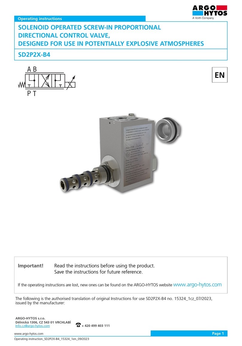
The SD2E2X-B hydraulic valve is a directly controlled solenoid operated spool valve. The valve is designed to be screwed into a shaped cavity in a
block with a 7/8-14 UNF connection thread. The shape and dimensions of the screw-in cavity conform to ISO/TR 17209 technical specification.
The product is generally intended for damming and controlling the direction of working fluid flow in hydraulic circuits by connecting individual
channels by means of a spool moving in the valve body.
1. Use of product
Overview of signal words and warning signs used in the text
Glossary of technical terms used
›A hydraulic mechanism is one in which energy is transmitted via the pressure energy of the working fluid.
›A hydraulic directional control valve is a valve designed to control the direction of movement or stop the output component of an appliance.
›The volumetric flow rate Q is the amount of liquid in volume units that flows through a given flow cross-section per time unit (SI unit is m3s-1,
in practice the unit l/min is used)
›The control solenoid is designed to reposition the valve spool that interconnects or closes the ports in the body. The solenoid consists of
an excitation coil which, by passing an electric current through the winding, generates a magnetic field which exerts a force on the armature of
the mechanical actuating system.
›The screw-in valve is designed to be screwed into the moulded cavity in the hydraulic block. The valve body is replaced by a steel sleeve in
which the spool or poppet moves.
›Pressure is the force acting per area unit (SI unit Pascal (1 Pa = Nm-2), in practice the unit used is bar (1bar = 0,1MPa)
Valves with ATEX certification according to Directive 2014/34/EU and IECEx certification according to IECEx OD 009 and related harmonized
standards may be used in explosive atmospheres consisting of mine gas, gas or dust. The valves are marked with the CE Ex mark of conformity and
are accompanied by a Declaration of Conformity.
Use in explosive atmospheres:
Equipment - group I, mines, where the explosive atmosphere of firedamp consists predominantly methane.
The valve has a high level of safety (EPL = Mb), which makes initiation unlikely during the interval between gas discharge and valve shutdown.
It is designed for category M2 devices that remain off after gas discharge.
Equipment - group II, where the explosive atmosphere consists of gasses other than mine gas.
The valve has a high level of safety (EPL = Gb) which allows the valve to be used in zones 1 and 2. The valve must not be used in zone 0.
There is a risk of explosion. The valve is certified for gas groups IIA (typical gas is propane), IIB (typical gas is ethylene) also for hydrogen from group IIC.
The joint dimensions do not meet the requirements for Group IIC acetylene.
Equipment - group III, where the explosive atmosphere consists of dust and flammable flying particles.
The valve has a high level of safety (EPL = Db) which allows the valve to be used in zones 21 and 22. The valve must not be used in zone 20. There is
a risk of explosion. The valve is certified for all dust groups - IIIA (flammable flying particles), IIIB (non-conductive dust) and IIIC (conductive dust).
Valve type Chamber designation The most common uses of the valve
ARGO-HYTOS EATON
SD2E2X-B2 B2 C-10-2 Damping of fluid flow.
SD2E2X-B3 B3 C-10-3 Switching the fluid flow to the two branches of the circuit.
Control of a single-acting appliance where the reciprocating motion is provided by the load.
SD2E2X-B4 B4 C-10-4 Controlling the direction of movement of the output component of a double-acting appliance.
Overview of other symbols and abbreviations used in the text
Symbol, designation Description of the meaning of the symbol, designation
AC, DC Designation for alternating (AC) and direct (DC) current, voltage
ATEX Explosive Atmospheres
EPL Equipment Protection Level (see EN 60079.0)
IEC International Electrotechnical Commission
NBR Rubber used for the manufacture of seals
PA Polyamide
PE Polyethylene
PU Polyurethane
DANGER Signal word combined with a warning sign used to signify that a dangerous situation which could result in
death or serious injury is imminent.
WARNING Signal word combined with a warning sign used to signify the occurrence of a potentially dangerous situation
that could result in death or serious injury if not avoided.
CAUTION Signal word combined with a warning sign used to signify a potentially hazardous situation which, if not
avoided, may result in minor or moderate injury.
