VORON NIGHTWATCH User manual

VORON NIGHTWATCH
We build space shuttles with gardening tools
so anyone can have a space shuttle of their own.
VERSION 2023-01-23

WWW.VORONDESIGN.COM
2
Before you begin on your journey, a word of caution.
This machine can maim, burn, and electrocute you if you are not careful.
Please do not become the first VORON fatality.
There is no special Reddit flair for that.
Please, read the entire manual before you start assembly.
As you begin wrenching, please check our Discord channels for
any tips and questions that may halt your progress.
Most of all, good luck!
The VORON Team
2

WWW.VORONDESIGN.COM
INTRODUCTION
3
PART PRINTING GUIDELINES
The Voron Team has provided the following print guidelines for you to follow in order to have the best chance at
success with your parts. There are often questions about substituting materials or changing printing standards,
but we recommend you follow these.
3D PRINTING PROCESS
Fused Deposition Modeling (FDM)
INFILL TYPE
Grid, Gyroid, Honeycomb, Triangle or Cubic
MATERIAL
ABS/ASA
INFILL PERCENTAGE
Recommended: 40%
LAYER HEIGHT
Recommended: 0.2mm
WALL COUNT
Recommended: 4
EXTRUSION WIDTH
Recommended: Forced 0.4mm
SOLID TOP/BOTTOM LAYERS
Recommended: 5
PRINT IT FORWARD (PIF)
Often times community members that have issues printing ABS will bootstrap themselves into a VORON using
our Print It Forward program. This is a service where approved members with VORON printers can make you
a functional set of parts to get your own machine up and running. Further Details about the PIF program can be
found on the Discord server or by visiting https://pif.voron.dev.
3

WWW.VORONDESIGN.COM
INTRODUCTION
4
HOW TO GET HELP
If you need assistance with your build, we’re here to help. Head on over to our Discord group and post your questions.
This is our primary medium to help VORON Users and we have a great community that can help you out if you get stuck.
https://discord.gg/voron
https://www.reddit.com/r/VORONDesign
https://forum.vorondesign.com
4

WWW.VORONDESIGN.COM
INTRODUCTION
5
THIS IS JUST A REFERENCE
This manual is designed to be a simple reference manual. Building a Voron can be a complex endeavour and for
that reason we recommend downloading the CAD files off our Github repository if there are sections you need
clarification on. It can sometimes be easier to follow along when you have the whole assembly in front of you.
DOCS https://docs.vorondesign.com
https://github.com/VoronDesign
REPORTING AN ISSUE
Should you find an issue in the documentation or have a suggestion for an improvement please consider opening an
issue on GitHub (https://github.com/VoronDesign/Pocket-Watch/issues). When raising an issue please include the
relevant page numbers and a short description; annotated screenshots are also very welcome. We periodically
update the manual based on the feedback we get.
5

WWW.VORONDESIGN.COM
HARDWARE - REFERENCES
6
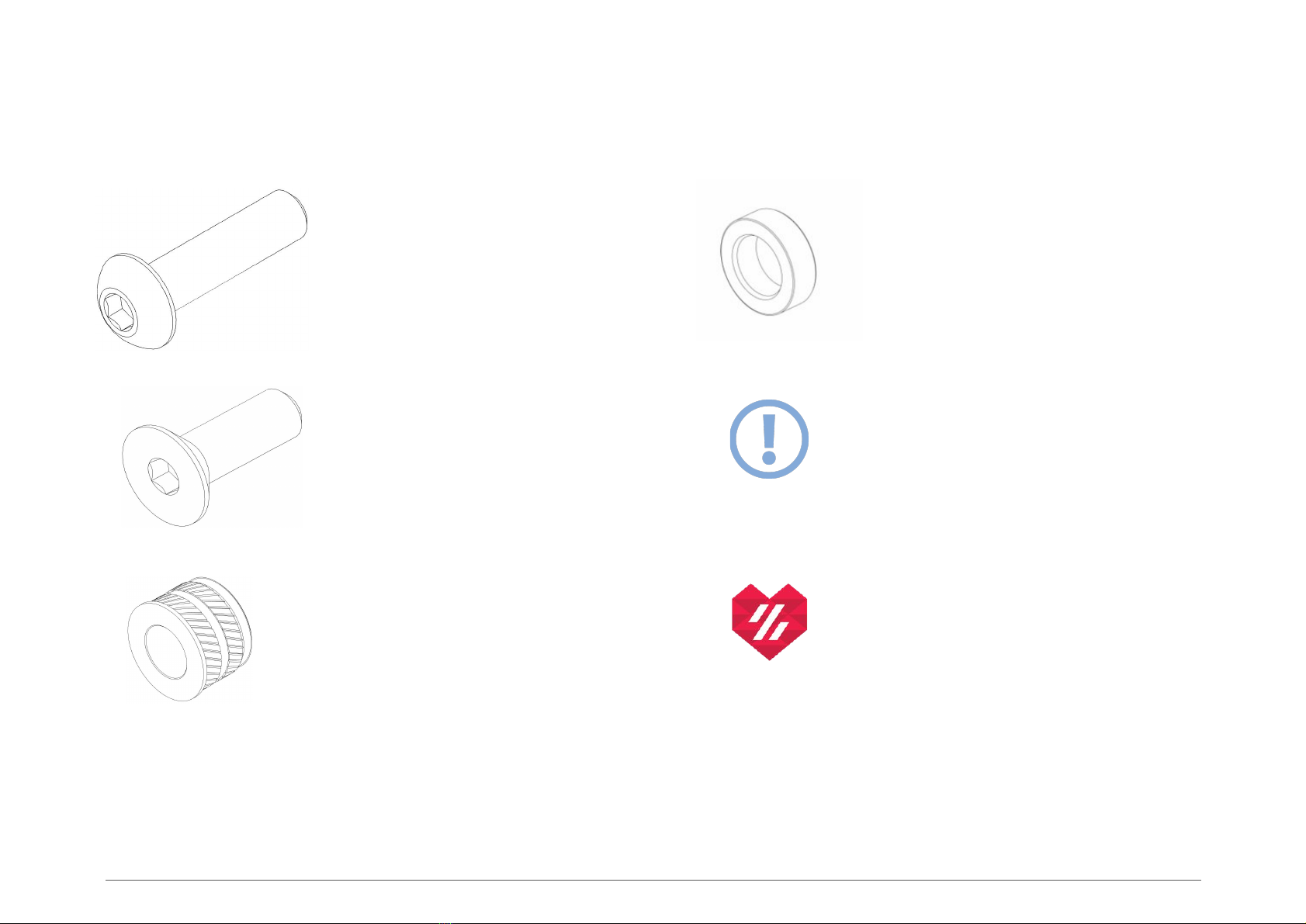
BUTTON HEAD CAP SCREW (BHCS)
Metric fastener with a domed shaped
head and hex drive. Most commonly
found in locations where M3 fasteners
are used.
ISO 7380-1
MR85 BEARING
A small ball bearing. 5x8x2.5mm
in size.
FLAT HEAD CAP SCREW (FHCS)
Metric fastener with a cone shaped head
and a flat top.
ISO 10642
ATTENTION BUBBLE
This logo denotes steps that are
common areas that mistakes can
occur.
HEAT SET INSERT
Heat the inserts with a soldering iron so
that they melt the plastic when installed.
As the plastic cools, it solidifies around
the knurls and ridges on the insert for
excellent resistance to both torque and
pull-out.
VORON HEART
Look for Voron heart next to
the part. It indicates that this is a
part that is usually printed in the
accent color.
6

WWW.VORONDESIGN.COM
COMPONENT PREP
77
THREADING INTO PLASTIC
This M2 screw threads into the
plastic of the Mid-Body part. It will be
used to adjust the meshing of the
BMG gears at a later step.
M2x6 FHCS
Heat Set Insert
GETTING A GOOD BOND
The heat set insert in the shuttle will
be in constant tension when
assembly is complete. It’s important
to get a good bond between the
insert and the plastic for this part.
KNOW YOUR TARGET AND BEYOND
Before heating your iron, check that you will not contact, or unintentionally melt,
surrounding plastic while installing heat inserts in the components.
Heat Set Insert

WWW.VORONDESIGN.COM
COMPONENT PREP
8
LUBRICATE BEARINGS
A lubrication film is required to ensure
smooth operation and longevity. Refer to the
Voron sourcing guide for lubricant options.
CHECK ORIENTATION
The larger gear section must be on
the right hand side. Check for any
rubbing or binding.
ADDED STRENGTH
This screw is there to
provide extra strength to
the guidler component
along its layer lines.
BUILT-IN SUPPORT
The guidler part prints with an
integrated support. Remove this
before moving to the next step.
BMG Idler Assembly
M2x10 Self Tapping
8

WWW.VORONDESIGN.COM
COMPONENT PREP
9
SHORT END OF THE SHAFT
Check the short end of the shaft. If it is longer than
3mm shorten it to under 3mm. The design for a
printed jig that can be used to help sand down the
shaft is included in the released files.
CHECK BEARING FIT
The bearings must slip on and off the shaft easily to
allow the gear to self center. Do not shim into position.
Pressing the bearings on the shaft will damage them.
Lightly sand the shaft if required.
Remove the bearings from the shaft after checking the
fit and continue with the assembly.
Printed Jig
9

WWW.VORONDESIGN.COM
COMPONENT PREP
10
MR85 Bearing
10
MR85 Bearing
Motor Plate Cover

WWW.VORONDESIGN.COM
ASSEMBLY
1111
Guidler
Shuttle
Latch

WWW.VORONDESIGN.COM
ASSEMBLY
1212
Mid Body
M3x10 BHCS
M3x25 BHCS
M3x20 BHCS
M3x16 BHCS
A FEW SCREWS LOOSE
Insert an M3x16 before continuing with assembly.
We’ll use this later to mount and adjust the stepper
motor.

WWW.VORONDESIGN.COM
ASSEMBLY
1313
CHECK ORIENTATION
The drive gear is mounted opposite of how it
is usually mounted in an extruder. Make sure
that the grub screw has sufficient contact
with the flat. Do not tighten the grub screw
yet, we will finalize the gears exact position
on the shaft in the next few steps.

WWW.VORONDESIGN.COM
ASSEMBLY
1414
M3x8 BHCS
M3x6 BHCS
A FEW SCREWS LOOSE (PART DEUX)
Insert an M3x8 into the Motor Plate before
continuing with assembly. We’ll use this later to
mount the stepper motor.

WWW.VORONDESIGN.COM
ASSEMBLY
1515
50T GEAR SPACING
For the next steps we need to ensure that
the 50T gear is not rubbing on any of the
plastic parts. Make sure your guidler door
is open so that you can freely adjust the
position of the 50T.

WWW.VORONDESIGN.COM
ASSEMBLY
1616
ALIGN THE DRIVE GEAR
While the 50T gear is centered, open the guidler and loosen the grub screw on the
BMG drive gear with a small allen key, then adjust its position left to right so that
the filament path is aligned with the gear teeth. Hold the 50T in position while
adjusting the drive gear so that it is still centered in its gap. Once happy, tighten the
grub screw. Be sure to not rotate the 50T gear while doing this so that the flat
section of the shaft is still under the grub screw location.
USE A PIECE OF FILAMENT
A piece of filament can be a handy guide to ensure
the grooves in your drive gear align correctly with
the filament path of the printed parts.

WWW.VORONDESIGN.COM
ASSEMBLY
1717
A NOTE ON SPRINGS
Longer/shorter/stiffer springs will change the tension
characteristics and have an impact on how well the
tension mechanism works. Consider buying the
original Bondtech part as those are known to work
well. If you sourced from a different vendor, check that
it is roughly 12mm long with an outer diameter of
6mm and a wire thickness of 1mm.
TENSION KNOB
Turning the thumb screw clockwise will increase the
tension and grip on the filament. Too much tension
will result in print issues.

WWW.VORONDESIGN.COM
ASSEMBLY
1818
LATCH SHUTTLE
The latch mechanism must seat into
the groove of the shuttle piece. This is
what allows the extruder to grip the
filament effectively.

WWW.VORONDESIGN.COM
ASSEMBLY
1919
ANTI SQUISH THINGYMAJIG
Softer and flexible materials will deform and extrude poorly under too much
tension. The Nightwatch adds an anti-squish thingymajig screw that sets the
minimum distance between the drive gear and the idler. Backing this screw out
increases this distance and tightening the screw in decreases this distance. Setting
this minimum distance helps to prevent the gears from meshing too tightly or
binding up in the extruder.
LIGHT TEETH MARKS
Close the latch and put a piece of filament through the
extruder, then spin the 50T with your finger to test the
feeding capability. You are looking for light teeth marks on
the surface of the filament. We will repeat this step once
more after the motor is installed.

WWW.VORONDESIGN.COM
ASSEMBLY
2020
Pancake Stepper Motor
GETTING GEARED UP
We are only slightly tightening this M3x16 for now.
We will be setting the proper gear mesh before fully
tightening the motor to the rear of the print head.
TOOL INSERTS
To access the screws that hold the stepper motor,
insert your driver of choice into these holes.
M3x16 BHCS
M3x8 BHCS
Table of contents
Other VORON Industrial Equipment manuals
Popular Industrial Equipment manuals by other brands

ABB
ABB HT583176 Operation manual

Hydac
Hydac RFX Installation and maintenance instructions

Genmitsu
Genmitsu CNC PROVerXL4030 user manual

Industrial Shields
Industrial Shields Raspberry PLC Series Quick user guide

Alemlube
Alemlube 52039 Owner technical manual

3M
3M 3M-Matic Accuglide NPH 11200 Instructions and parts list