Industrial Shields Raspberry PLC Series Instruction manual
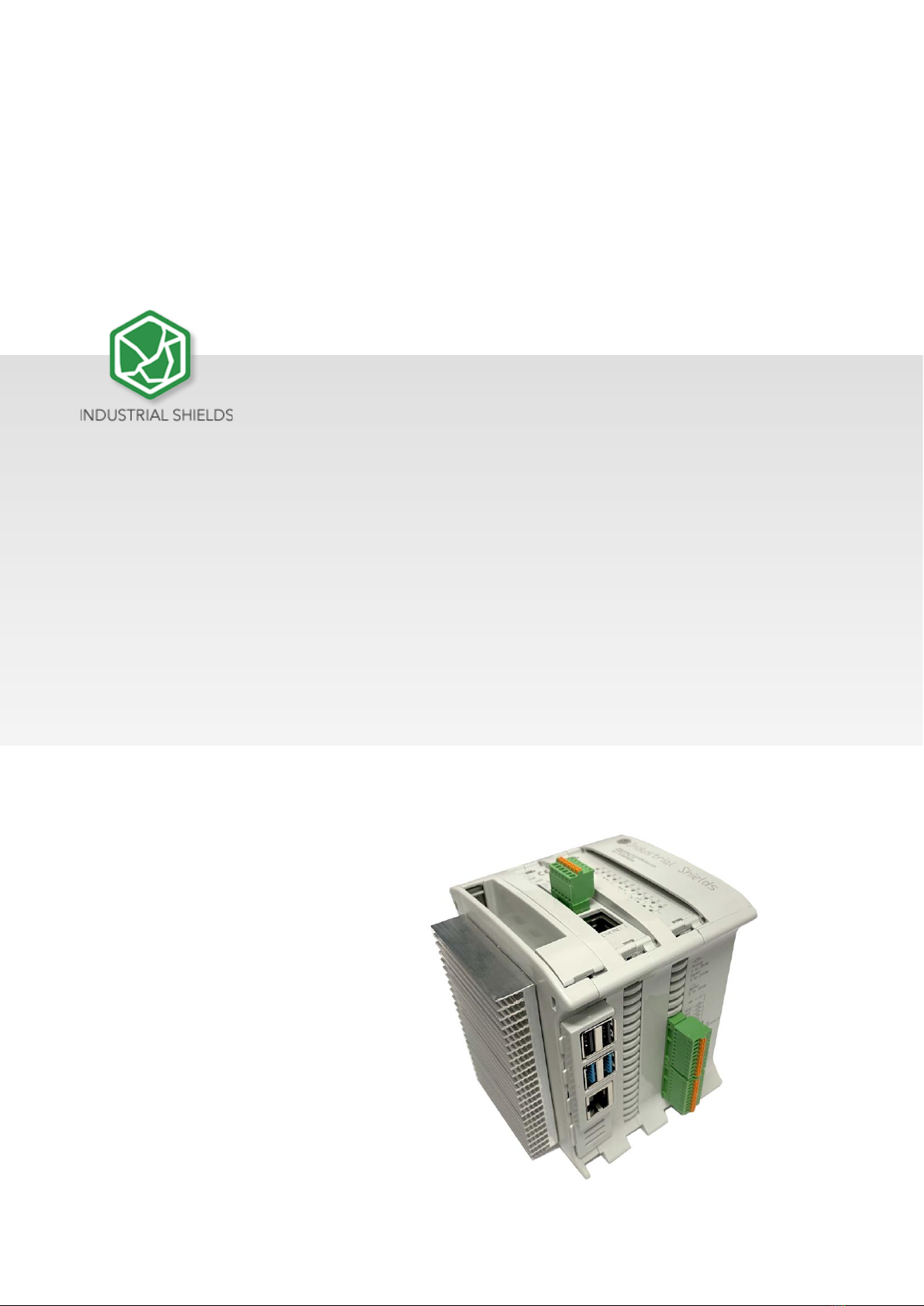
RASPBERRY PLC FAMILY
RASPBERRY PLC FAMILY


Rev. 8: 29-04-2021
3
Preface
This User Guide is been implemented by Boot & Work, S.L. working
under the name Industrial Shields.
Purpose of the manual
The information contained in this manual can be used as a reference to operate and
get a better understanding of the technical data of the signal modules, power supply
modules and interface modules.
Intended Audience
This User Guide is intended for the following audience:
•Persons in charge of introducing automation devices.
•Persons who design automation systems.
•Persons who install or connect automation devices.
•Persons who manage working automation installation.
Warnings:
•Unused pins should not be connected. Ignoring the directive may damage the
controller.
•Before using this product, it is the responsibility of the user to read the product’s User
Guide and all accompanying documentation.
•Industrial Shields PLCs must be powered between 12Vdc and 24Vdc. If a higher voltage
is supplied to the equipment can suffer irreversible damage.
•Maintenance must be performed by qualified personnel familiarized with the
construction, operation, and hazards involved with the control.
•Maintenance should be performed with the control out of operation and disconnected
from all sources of power.
•The Industrial Shields Family PLCs are Open Type Controllers. It is required that you
install the Raspberry PLC in a housing, cabinet, or electric control room. Entry to the
housing, cabinet, or electric control room should be limited to authorized personnel.
•Inside the housting, cabinet or electric control room, the Industrial Shields PLC must be
at a minimum distance from the rest of the components of a minimum of 25 cm, it can
be severely damaged.
•Failure to follow these installation requirements could result in severe personal injury
and/or property damage. Always follow these requirements when installing Raspberry
family PLCs.

Rev. 8: 29-04-2021
4
•In case of installation or maintenance of the PLC please follow the instructions marked
in the Installation and Maintenance section on the User Guide.
•Do not disconnect equipment when a flammable or combustible atmosphere is
present.
•Disconnection of equipment when a flammable or combustible atmosphere is present
may cause a fire or explosion which could result in death, serious injury and/or
property damage.
•Inside the encapsulated, there are supercapacitors if 25F which can be dangerous. Be
careful with them.

Rev. 8: 29-04-2021
5
Table of Contents
General Description RASPBERRY PLC FAMILY Product....................................................... 8
Reference Table................................................................................................................ 8
Zones Table....................................................................................................................... 9
Measures Table ................................................................................................................ 9
Zone - Nomenclature...................................................................................................... 10
Zone Distribution............................................................................................................ 10
Zone Features................................................................................................................. 11
Mechanical dimension ................................................................................................... 12
General Features............................................................................................................ 13
Technical Specifications: ........................................................................................................ 14
General Specifications:................................................................................................... 14
Performance Specification: ............................................................................................ 15
Symbology ...................................................................................................................... 15
Precautions ............................................................................................................................ 16
Raspberry Board............................................................................................................. 16
Intended Audience......................................................................................................... 16
General Precautions....................................................................................................... 16
How to connect PLC to power supply.................................................................................... 17
How to access to the Raspberry PLC...................................................................................... 18
Raspberry PLC access ..................................................................................................... 18
5.1.1 Linux..................................................................................................................... 18
5.1.2 Windows .............................................................................................................. 20
How to change the IP............................................................................................................. 22
Linux ............................................................................................................................... 22
Windows......................................................................................................................... 22
How to transfer files from the PC to the Raspberry PLC........................................................ 24
Windows......................................................................................................................... 24
Linux ............................................................................................................................... 25
Raspberry PLC Family Pinout ................................................................................................. 26
I/Os Table ....................................................................................................................... 26

Rev. 8: 29-04-2021
6
0 Zone connection (Communications) ........................................................................... 27
Analog/Digital Zone connection (I/Os)........................................................................... 29
Relay Zone connection (I/Os) ......................................................................................... 30
Interrupt equivalence table............................................................................................ 31
Switch Configuration.............................................................................................................. 31
Analog / Digital Zone...................................................................................................... 31
Relay Zone ...................................................................................................................... 31
I/O RASPBERRY PLC 3.3V pins ................................................................................................ 32
Serial –RX/TX ................................................................................................................. 32
SPI0 –MISO/MOSI/SCK .................................................................................................. 33
GPIO25............................................................................................................................ 33
Equivalence Table .................................................................................................................. 34
Pin-Out............................................................................................................................ 34
11.1.1 Analog/Digital Devices Analog I/Os ..................................................................... 34
11.1.2 Digital I/Os............................................................................................................ 35
11.1.3 Relay Devices Analog I/Os.................................................................................... 35
11.1.4 Digital I/Os............................................................................................................ 36
11.1.5 Relay..................................................................................................................... 36
Internal I2C and SPI Connections........................................................................................... 37
Input & Output control .......................................................................................................... 37
Scripts Location .............................................................................................................. 37
13.1.1 Analog/Digital Shield............................................................................................ 37
13.1.2 Relay Shield.......................................................................................................... 37
13.1.3 Generic Shield ...................................................................................................... 37
Set Value......................................................................................................................... 38
Get Value........................................................................................................................ 40
Fan Functions ................................................................................................................. 41
13.4.1 Start Fan............................................................................................................... 41
13.4.2 Stop Fan ............................................................................................................... 41
A & B Zone Features: Communications & RTC & uSD............................................................ 42
RS-485............................................................................................................................. 42
I2C................................................................................................................................... 42
SPI................................................................................................................................... 43
TTL .................................................................................................................................. 43

Rev. 8: 29-04-2021
7
Ethernet.......................................................................................................................... 43
Wi-Fi ............................................................................................................................... 44
BLE .................................................................................................................................. 44
RTC.................................................................................................................................. 46
uSD ................................................................................................................................. 46
Additional family features...................................................................................................... 48
GPRS Family.................................................................................................................... 48
Revision Table ........................................................................................................................ 50

Rev. 8: 29-04-2021
8
General Description RASPBERRY PLC FAMILY Product
Reference Table
Rev. 8: 29-04-2021
9
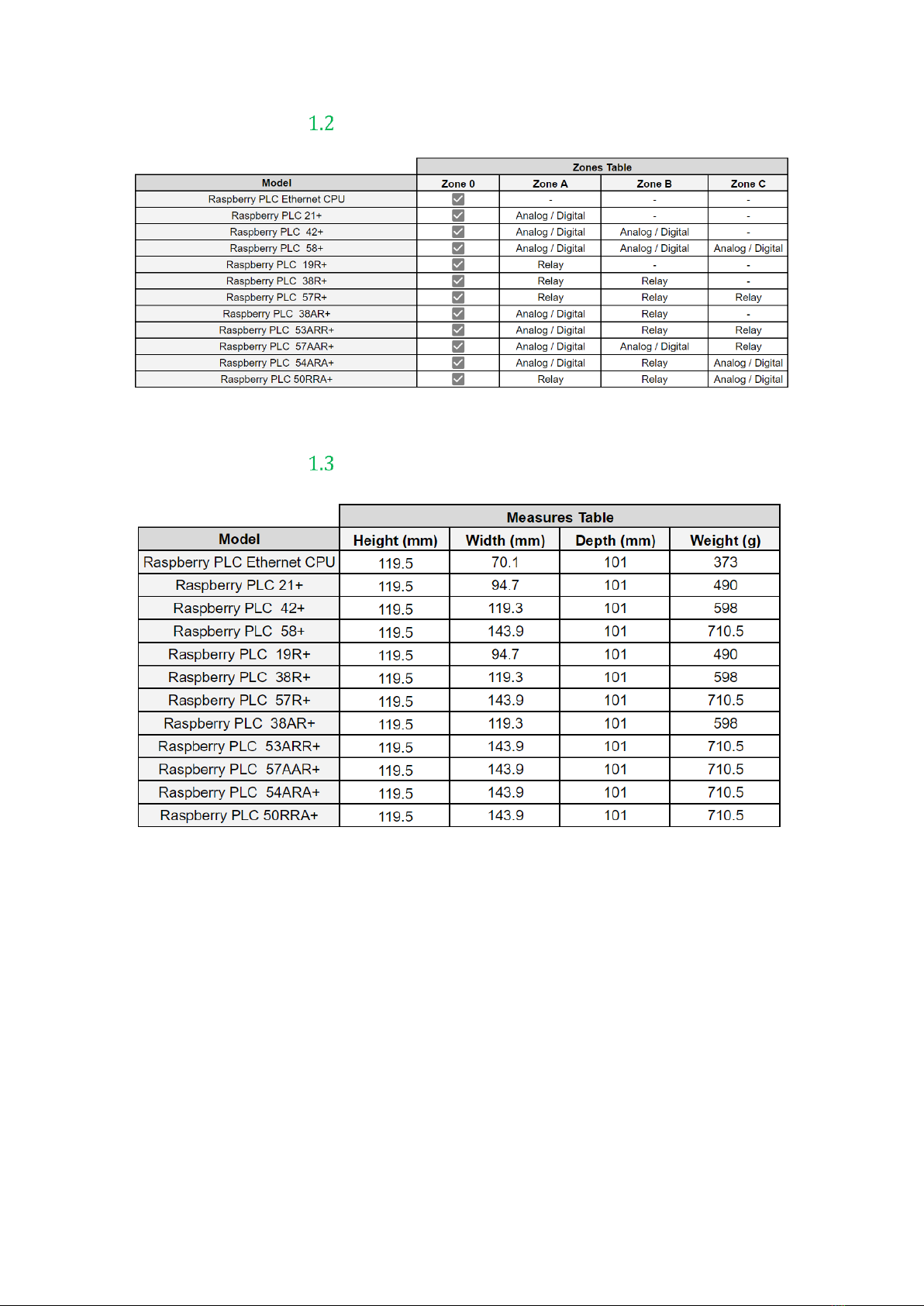
Zones Table
Measures Table
Rev. 8: 29-04-2021
10
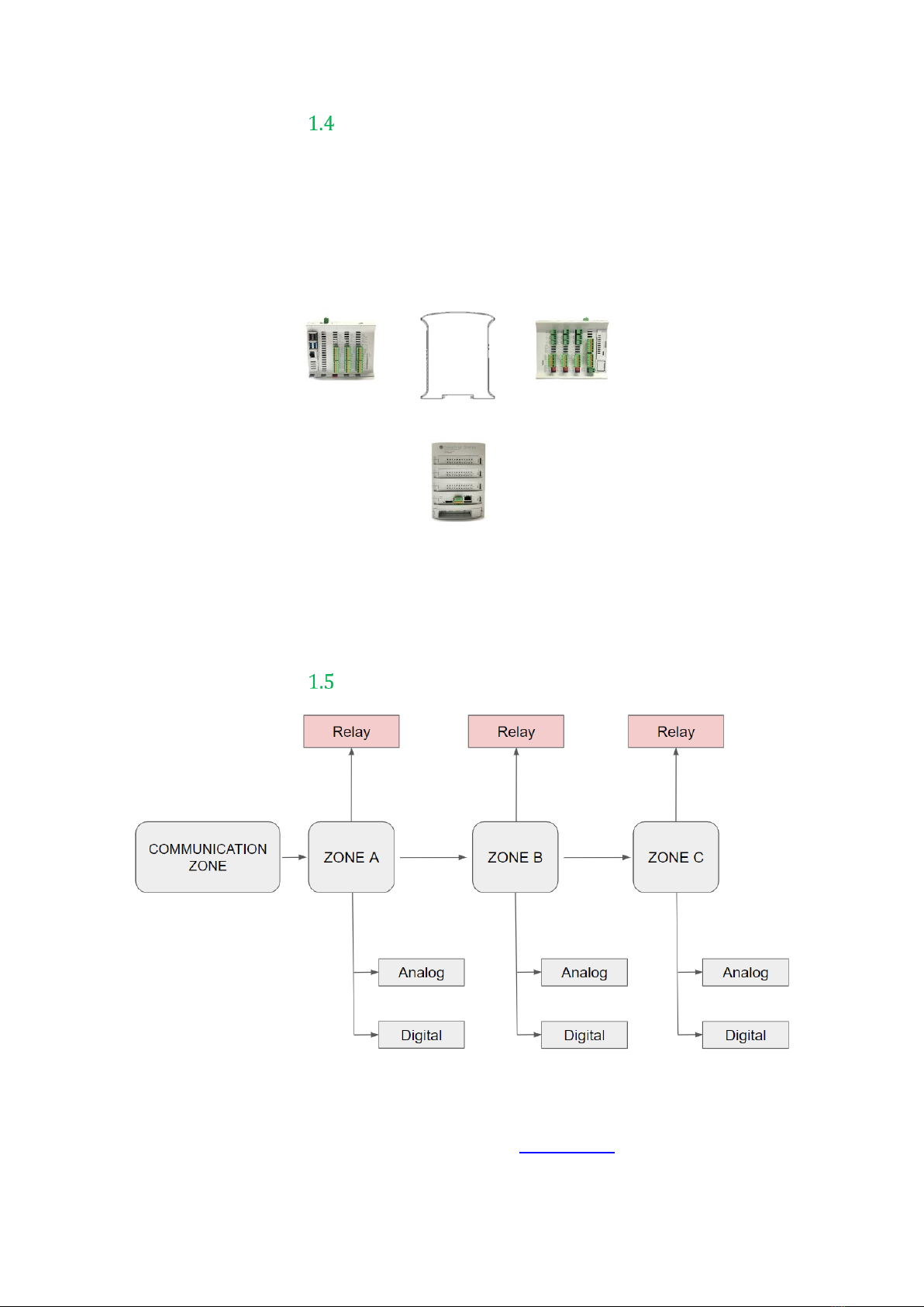
Zone - Nomenclature
The nomenclature shown in this point will be used in the whole User Guide, so it is
important to understand this nomenclature.
The nomenclature to differentiate the zones is based on Alphanumeric values, being 0
the internal communication shield and A, B or C the I/Os or Relay shield.
●The inputs in the zone A/B/C are named IX.X, being X any number suitable in
the Shield. Outputs are named as QX.X.
Zone Distribution
This is the possible zones scheme, whether the zone is Analog/Digital or Relay
depends on your device, you can consult it on the Zones Table. The distribution of the
different features that provide the Raspberry PLC Family are described below.
0 ZONE
A ZONE
B ZONE
C ZONE
C ZONE
B ZONE
A ZONE
0 ZONE
C ZONE
B ZONE
A ZONE
0 ZONE

Rev. 8: 29-04-2021
11
Zone Features
Shield
Zone Characteristics
Communication Shield
(2x) Ethernet
(4x) USB
(1x) I2C
(1x) TTL
(2x) HALF Duplex RS-485
(1x) SPI external Port
(1x) RTC
(1x) Bluetooth
(1x) Wi-Fi
(1x) μSD Socket
(1X) CAN
(x1) μHDMI
Analog Shield
13 Inputs:
8 Outputs:
13 Digital inputs, 6 of which can work as Analog Input
8 Digital Outputs, 3 of which can work as Analog Output
Relay Shield
6 Inputs:
11 Outputs:
6 Digital Inputs, 4 of which can work as Analog Input
8 Relay Outputs
3 Digital Outputs, 3 of which can work as Analog Output

Rev. 8: 29-04-2021
13
General Features
CONNECTABLE PLC RASPBERRY 24 VCC
MODEL TYPE
Controller General Specifications
Information
Input Voltage
12 to 24 Vdc
Fuse Protection (2.5 A) Polarity
protection
I max.
1.5 A
Size
Consult the Measure Table section
Clock Speed
1.5 GHz
Flash Memory
-
SRAM
2 - 4 - 8 GB
Communications
I2C –Ethernet (x2) –USB (x4) –(x2) RS485 –SPI –WiFi –
Bluetooth - Serial TTL –CAN - μSD - RTC
MAX485 –W5500
Digital GPIO25
(3.3 V)
3.3 V
An/Dig Input 10bit
(0-10Vcc)
0 to 10Vac
Rated Voltage: 10Vac
5 to 24Vdc
I min: 2 to 12 mA
Galvanic Isolation
Rated Voltage: 24 Vdc
Digital Isolated Input (24Vcc)
5 to 24Vdc
I min: 2 to 12 mA
Galvanic Isolation
Rated Voltage: 24 Vdc
* Interrupt isolated Input HS
(24Vcc)
5 to 24Vdc
I min: 2 to 12 mA
Galvanic Isolation
Rated Voltage: 24Vdc
Analog Output 8 bits
(0 - 10 Vcc)
0 to 10 Vdc
I max: 20 mA
Separated PCB Ground
Digital Isolated Output
(24 Vcc)
5 to 24 Vdc
I max: 70 mA
Galvanic Isolation
Diode Protected for Relay
I max 24 Vdc: 410 mA
Relay Output
(220 Vac)
24 VDC / 220 VAC
I max: 5 A
Galvanic Isolation
Diode Protected for Relay

Rev. 8: 29-04-2021
14
PWM Isolated Output 8 bits
(24 Vcc)
5 to 24 Vdc
I max: 70 mA
Galvanic Isolation
Diode Protected for Relay
Expandability
I2C: 127 elements –Serial Port RS485
* By using this type of signal can no longer use Digital signal (24Vdc)
Technical Specifications:
General Specifications:
Item
RASPBERRY PLC
Power supply
voltage
DC power supply
12 to 24Vdc
Operating
voltage range
DC power supply
11.4 to 25.4Vdc
Power
consumption
DC power supply
30 W max.
External
power supply
Power supply
voltage
24 Vdc
Power supply
output capacity
700 Ma
Insulation resistance
20MΩ min.at 500Vdc between the AC terminals and the protective earth terminal.
Dielectric strength
2.300 VAC at 50/60 Hz for one minute with a leakage current of 10mA max. Between all the
external AC terminals and the protective ground terminal.
Shock resistance
80m/s2in the X, Y and Z direction 2 times each.
Ambient temperature (operating)
0º to 50ºC with Raspberry OS Lite / 0º to 40º with Raspberry OS Desktop
Ambient humidity (operating)
10% to 90% (no condensation)
Ambient environment (operating)
With no corrosive gas
Ambient temperature (storage)
-20º to 60ºC
Power supply holding time
2ms min.
Weight
Consult the Measure Table section

Rev. 8: 29-04-2021
15
Performance Specification:
Raspberry Board
Raspberry Pi 4
I/O control method
Combination of the cyclic scan and immediate refresh processing methods.
Programming language
Linux applications : Python, C++, etc.
Program capacity (SRAM)
2 –4 - 8 GB
EEPROM
4 MB/512 KB
Clock Speed
1.5 GHz
CPU
Broadcom BCM2711, Quad core Cortex-A72 (ARM v8) 64-bit SoC @ 1.5GHz
Symbology
Table that includes all the symbology that is used in the serigraph of the RASPBERRY PLC
FAMILY:
Symbol
Standard No. /
Standard Title
Standard
Reference No. /
Symbol Title
Symbol Meaning
IEC 60417 /
Graphical symbols
for use on
equipment
5031 / Direct
Current
Indicates that the equipment is
suitable for direct current only;
to identify relevant terminals
IEC 60417 /
Graphical symbols
for use on
equipment
5032 / Alternating
Current
Indicates that the equipment is
suitable for alternating current
only; to identify relevant
terminals
IEC 60417 /
Graphical symbols
for use on
equipment
5130 / Pulse
General
To identify the control by
which a pulse is started.
IEC 60417 /
Graphical symbols
for use on
equipment
5017 / Earth,
Ground
To identify an earth (ground)
terminal in cases where
neither the symbol 5018 nor
5019 is explicitly required.
IEC 60417 /
Graphical symbols
for use on
equipment
5115 / Signal lamp
To identify the switch by
means of which the signal
lamp(s) is (are) switched on or
off.
Medical Devices
Directive
93/42/EEC
CE Marking
CE marking indicates that a
product complies with
applicable European Union
regulations

Rev. 8: 29-04-2021
16
ISO 7000/
Graphical symbols
for use on
equipment
0434B /
Warning symbol
Indicates a potentially
hazardous situation which, if
not avoided, could result in
death or serious injury
ISO 7000/
Graphical symbols
for use on
equipment
5036 / Dangerous
Voltage
To indicate hazards arising
from dangerous voltages
Precautions
Read this manual before attempting to use the RASPBERRY PLC FAMILY and follow its
descriptions for reference during operation.
Raspberry Board
The RASPBERRY PLC FAMILY includes a Raspberry Pi 4 Board as controller.
Intended Audience
This manual is intended for technicians, which must have knowledge on electrical systems.
General Precautions
The user must operate Raspberry PLC according to the performance specifications described in
this manual.
Before using the RASPBERRY PLC FAMILY under different conditions from what has been
specified in this manual or integrating into nuclear control systems, railroad systems, aviation
systems, vehicles, combustion systems, medical equipment, amusement machines, safety
equipment and other systems, machines, and equipment that may have a serious influence on
lives and property if used improperly, consult your INDUSTRIAL SHIELDS representative. Ensure
that the rating and performance characteristics of the Raspberry PLC are sufficient for the
systems, machines, and equipment, and be sure to provide the systems, machines, and
equipment double safety mechanisms. This manual provides information for programming and
operating the Raspberry PLC.
Rev. 8: 29-04-2021
17
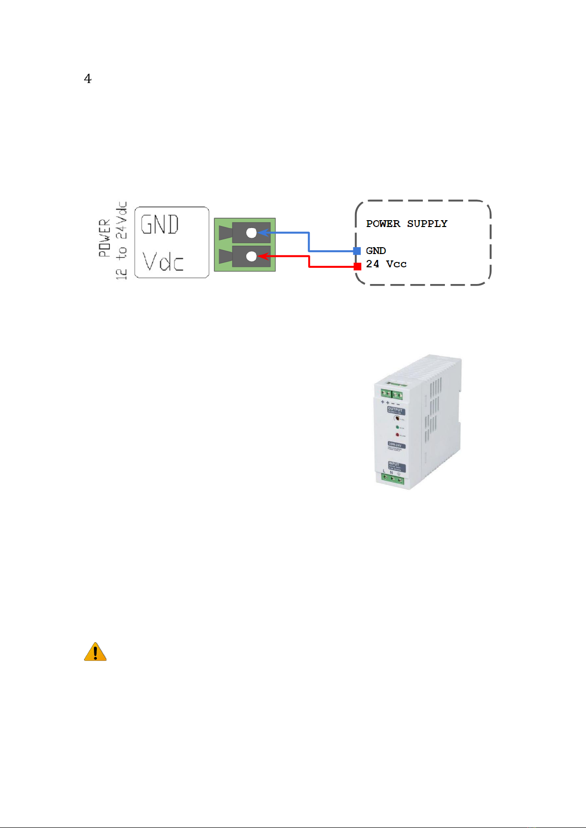
How to connect PLC to power supply
-Raspberry PI Family PLCs are 12-24Vdc supplied. IMPORTANT: The polarity IS NOT
REVERSAL!
-Make sure that the live and GND connector of the power supply match the PLC.
-Make sure that the power supply mains output is not higher than 24Vdc.
-Suggested power suppliers
The standard, Part 1 of IEC 61010, sets the general safety requirements for the following types
of electrical devices and their accessories, regardless of where use of the device is intended.
The equipment must be powered from an external power source in accordance with IEC
61010-1, whose output is MBTS and is limited in power according to section 9.4 of IEC 61010-
1.
Warning:
Once the equipment is installed inside an electrical cabinet, the MTBS cables of the equipment
must be separated from the dangerous voltage cables.
Compact DIN rail power supply. Assembled on 35mm
DIN Rail:
- 24Vdc
- 10A
- 240W
Industrial Shields power supplies provide parallel
operation, overvoltage protection, and overcurrent
protection. There is a LED inductor for power status,
the power supply is certified according to UL.
Rev. 8: 29-04-2021
18
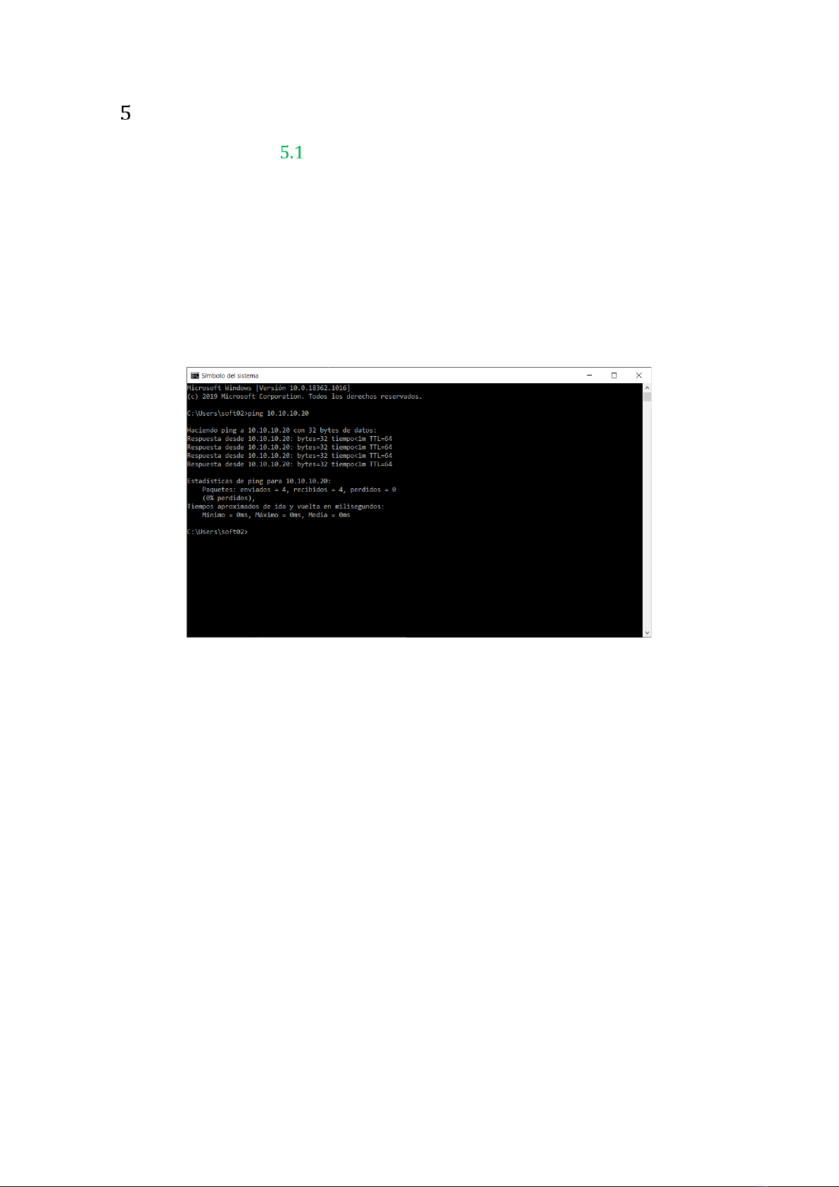
How to access to the Raspberry PLC
Raspberry PLC access
To facilitate the connection to the Raspberry PLC, our company has set a default IP for it. For
the first time of use, an Ethernet connection between the Raspberry PLC and a PC will be
necessary. The Raspberry is given with the local IP address 10.10.10.20/24*, the default user is
pi and the password is raspberry. For connecting to it, you must change your local address for
being in the same local network as the Raspberry. After the first connection you can add users
or change each user’s password anytime. In order to know if the Raspberry is connected and
the Ethernet connection is going on, a ping command can be run on the terminal (for windows
users enter cnm in the windows searching tab to open it):
*Note: To use this local IP address you must connect the Ethernet cable to the Ethernet port
located in the right side of the PLC. Do not use the upper side Ethernet port for this purpose.
The steps to follow for both Linux and Windows are explained below:
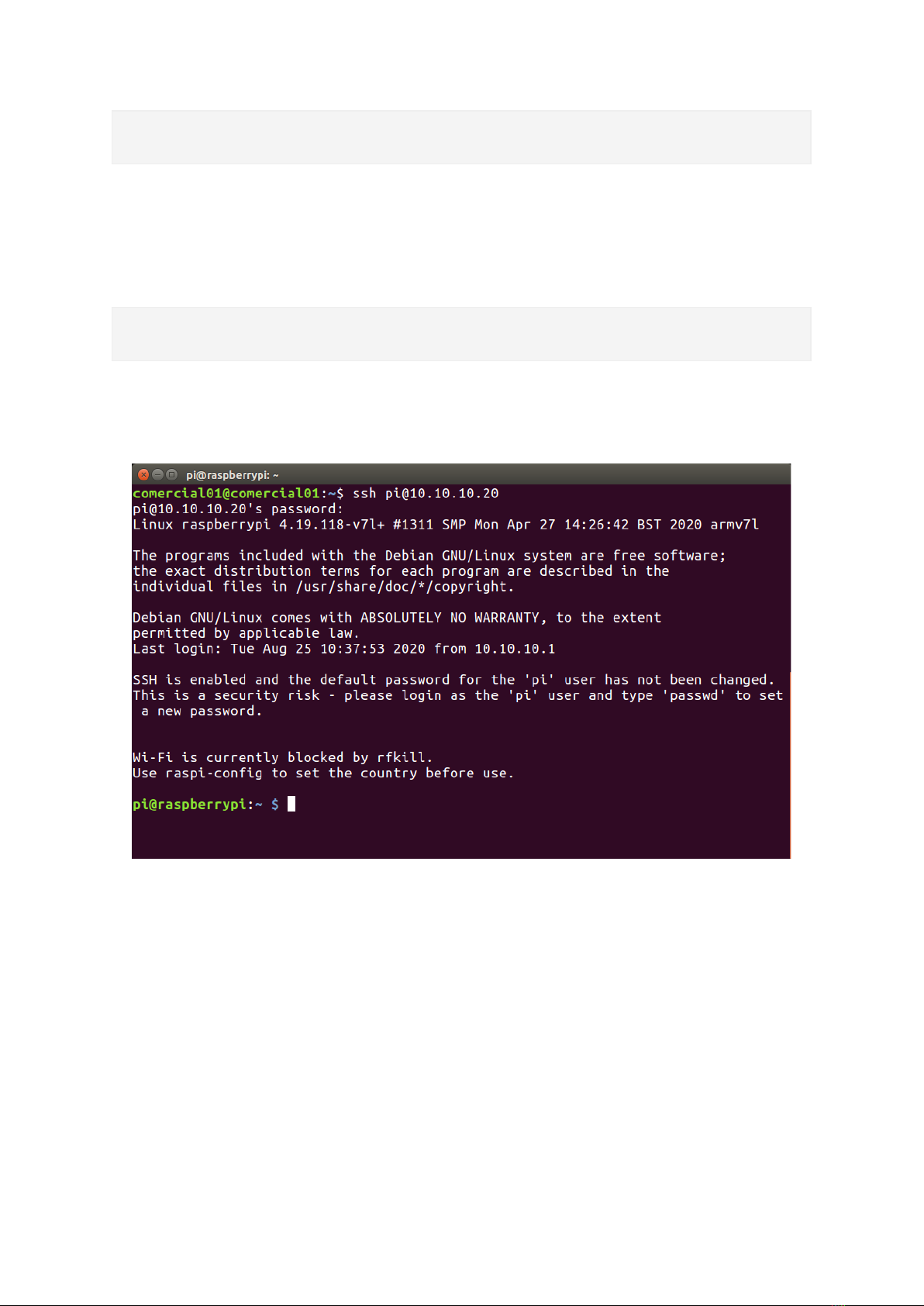
5.1.1 Linux
In order to access the Raspberry PLC, Linux users have to enter by SSH protocol, which should
have been installed before by the user. As has been said, the Raspberry is given with a local IP
address by default for making an easier path for the customer. So, first of all we have to check
if our local Ethernet Network is set with the same local IP address as our raspberrian device. In
case that you do not know how to set it, check the section 6 of the guide. As have been
mentioned before, you can use the ping command with the address 10.10.10.20 as option:
Rev. 8: 29-04-2021
19
$ping 10.10.10.20
If the ping works successfully means that our connection is ready. If not, you can check section
6 again or read our blog about changing the local IP.
For accessing to the Raspberry PLC we will run the command ssh shown below:
$ssh [email protected]
The connection will start, but first the password provided before will be required. If the
username and password are correct, you can start the SSH session.
When an SSH connection is made for the first time, the server delivers the server's public key
to the SSH client. The system will alert you to this and offer you the option of accepting the key
or rejecting it. You have to accept the key, as it will be stored in the register and will be used to
contrast it with the one sent by the server on each connection. If for some reason the key
changes, a new notice is generated in which the authenticity of the received key will be raised,
since someone could be posing as the server to which we want to connect.
Once connected, will be a full access to the Raspberry PLC and the user will be able to control
it and set the functions needed. Also new users or the password could be changed as the
device IP. The commands for going through the Raspberry are the same as the Linux terminal.
The most useful are the following:
•cd: to navigate through the Linux files and directories.
•ls: is used to view the contents of a directory.
This manual suits for next models
12
Table of contents
Popular Industrial Equipment manuals by other brands

Schaeffler
Schaeffler FAG PULLER-2ARM user manual

Linear Technology
Linear Technology LTC6416 Demo Manual

Aerovent
Aerovent IM-502 Installation, operation & maintenance manual

Endress+Hauser
Endress+Hauser Cleanfit COA451 operating instructions

Vestil
Vestil SPB-P-72 instruction manual

Spartan
Spartan TE200 Series user manual


goodnature
goodnature AA-375R owner's manual

Watkiss
Watkiss Vario operating manual

Delachaux
Delachaux Conductix-Wampfler 040804 Series Operating instruction

Schäfter+Kirchhoff
Schäfter+Kirchhoff 60FC-T Series quick start guide

BROSA
BROSA 0206 operating manual

Magnetek
Magnetek Electrobar 8-Bar instruction manual