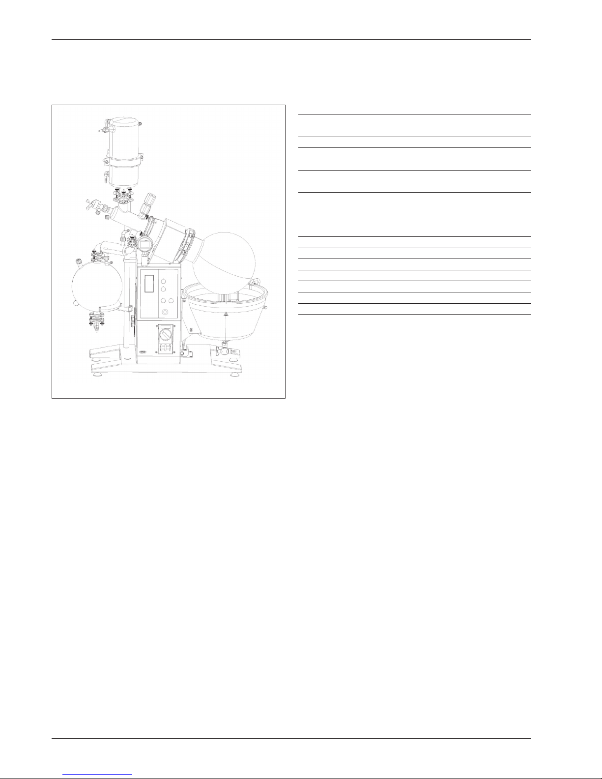
Buchi Rotavapor R-220 EX User manual

Rotavapor®R-220 EX
Operation Manual
096987K en

Imprint
Product Identification:
Operation Manual (Original), Rotavapor® R-220 EX
096987K en
Publication date: 02.2018
BÜCHI Labortechnik AG
Meierseggstrasse 40
Postfach
CH-9230 Flawil 1
E-Mail: quality@buchi.com
BUCHI reserves the right to make changes to the manual as deemed necessary in the light of experience; espe-
cially in respect to structure, illustrations and technical detail.
This manual is copyright. Information from it may not be reproduced, distributed, or used for competitive purposes,
nor made available to third parties. The manufacture of any component with the aid of this manual without prior
written agreement is also prohibited.

3
Rotavapor R-220 EX
Table of Contents
Table of Contents
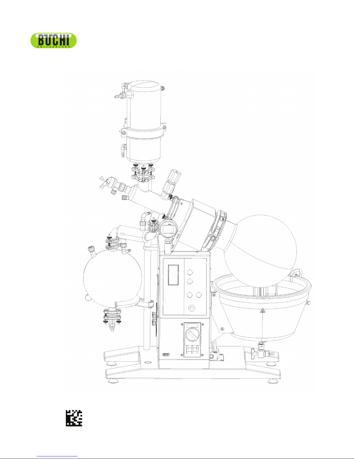
Read this Operating Manual through carefully
before using the Rotavapor R-220 EX.
Always keep these Instructions readily avai-
lable in the immediate vicinity of the unit so
that they make be consulted at any time.
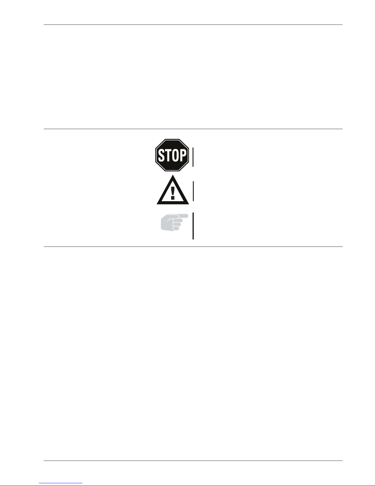
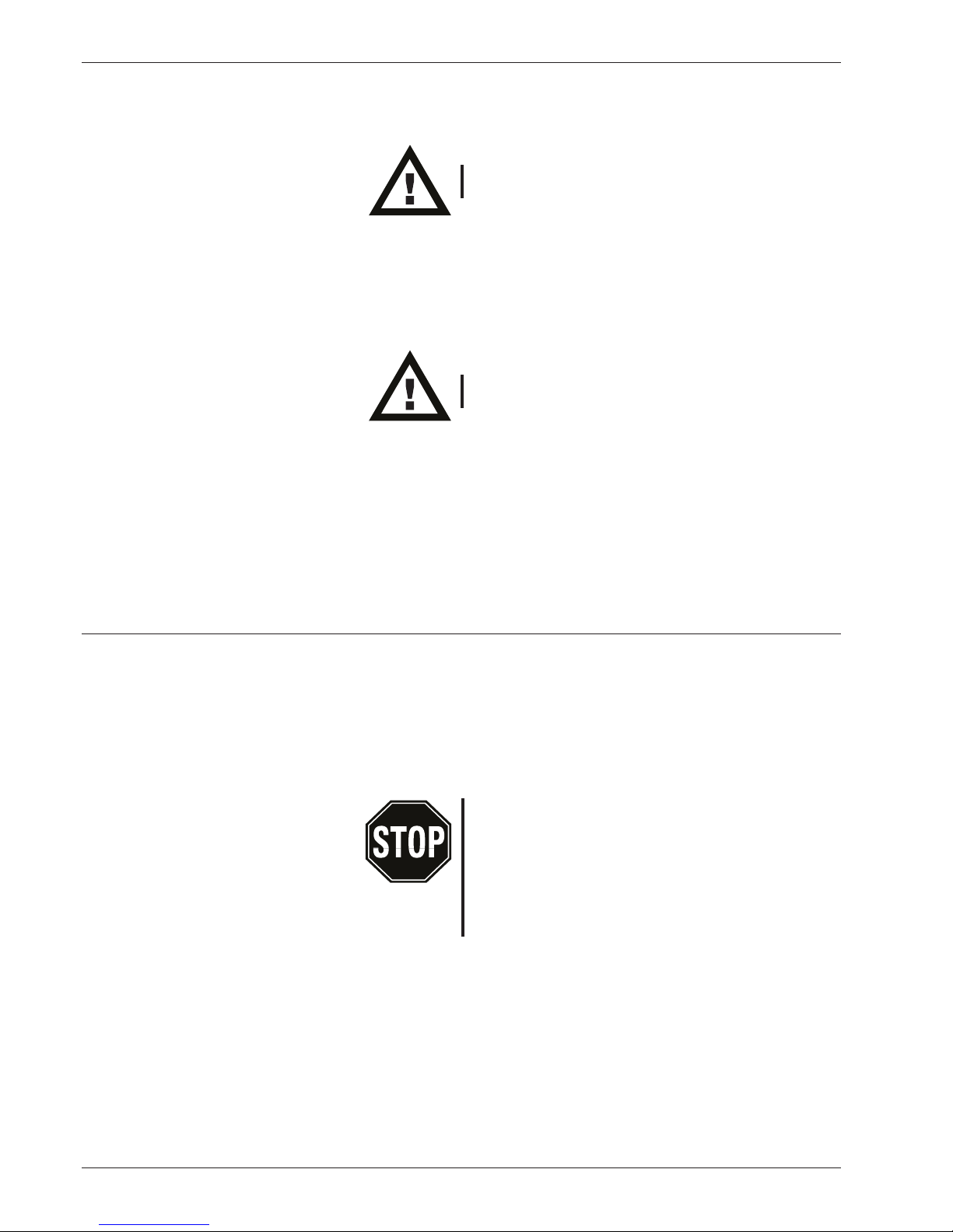
Chapter 2 contains important safety rules
which must be observed to ensure the safe
operation of the rotary evaporator.
1 Scope of Delivery 4
2 Safety 5
3 Function 10
3.1 Principle of Operation 10
4Putting into Operation 11
4.1 Installation Location 11
4.2 Unpacking 11
4.3 Connecting to the Source of Energy 12
4.4 Setting up the Support Rod 12
4.5 Attachment of the EasyClamp 13
4.6 Removal of the EasyClamp 13
4.7 Installation of the Reflux Glass Assembly 14
4.8 Installation of the Downgrade Glass Assembly 15
4.9 Installation of the Downgrade Glass Assembly
with a 2nd Cooler 16
4.10 Installation of the Receiving Fixtureg 17
4.11 Attaching and Removing Flasks 18
4.12 Hose Couplings 20
4.13 Operating the Shut-off tap 22
4.14 Bath Replenishment (Optional) 22
4.15 Reset of the over-temperature protection 23
4.16 Heating Medium 24
4.17 Compressed Air Connection 24
4.18 Vacuum Controller 24
4.19 Splash Protector 25
4.20 Checking Installation 25
5Operation 26
5.1 Arrangement of the Operator Control and
Display Elements 26
5.2 Setting the Parameters 27
5.3 Vacuum Controller 28
5.4 Splash Protector 32
5.5 Tips and Tricks 33
5.6 Table of Solvents 35
6Maintenance 35
6.1 Troubleshooting 35
6.2 Taking Apart the Snap Flange Coupling 35
6.3 Assembling the Snap Flange Coupling 36
6.4 Removing the Evaporating Flask Seal 36
6.5 Inserting the Evaporating Flask Seal 37
6.6 Replacement of the Seals for the Distribution Head37
6.7 Replacement of the Vacuum Seal 38
6.8 Cleaning 38
6.9 Vacuum Seal 39
6.10 Testing for Leaks 39
6.11 Customer Service 39
7 Taking out of Operation 40
7.1 Storage 40
7.2 Packing/Transport 40
7.3 Waste Disposal 40
8 Spare Parts and Accessories 41
8.1 Glass Assemblies D, D2, DB, DB2 43
8.2 Glass Assemblies R, RB, C 45
8.3 Miscellaneous 46
8.4 Accessories 49
9 Appendix 51
9.1 Technical Data 51
9.2 Materials Used 51
9.3 Error Messages 52
9.4 FCC requirements (for USA and Canada) 52
9.5 Declaration of conformity 53
We reserve the right to make technical changes without prior
notification. No portion of this Operating Manual may be re-
produced, processed using electronic or optical systems,
duplicated, or distributed in any form without the prior written
approval of BÜCHI Labortechnik AG.
All rights reserved. © BÜCHI Labortechnik AG, 2015
en, Ordering No.
R-220 EX Operation Manual 096987

4
Rotavapor R-220 EX
1 Scope of Delivery
1 Scope of delivery
Fig. 1.1: R-220 Ex Overall View
Component
1 Chassis, complete, with control and
driving unit and heating bath
1 6L, 10L or 20L Evaporation flask
1 Receiving flask 1 x 10L Single receiver or
2 x 10L Interchangeable receivers
1 Glass assembly
(Refer to Chap. 4.7 - 4.9 for Figure)
Table 1.1: Scope of Supply
Standard Accessories: Ordering No.
1 Seal tool 20075
1 Operating Manual
German 96986
English 96987
French 96988
Italian 96989
Spanish 96990
Table 1.2: Standard Accessories

5
Rotavapor R-220 EX
2 Safety
2 Safety
This unit has been built in accordance with the latest state
of the art and with recognized rules of safety.
Nevertheless there are certain risks and dangers entailed
with this unit:
• whenever the unit is operated by individuals who lack
sufficient training;
• whenever the unit is used for some purpose other than
its authorized use.
2.1 Symbols
Stop
Information on dangers that can cause serious ma-
terial damage and severe personal injuries or death.
Warning
Information on dangers thatvvcan be injurious to one’s health
or cause material damage.
Note
Information pointing out technical requirements. A failure to
observe such information can lead to malfunctions, uneco-
nomical operation, and losses in production.
2.2 Responsibilities of the Operator
This unit may only be used by technical staff and by indi-
viduals who, based on their training or their professional
experience, have a good understanding of the dangers that
can arise from the its operation.
Staff who do not have this training and individuals who are
currently in training must be given careful instructions. This
Operating Manual should be used as the basis for such
training.

6
Rotavapor R-220 EX
2 Safety
2.3 Authorized Use
The rotary evaporator has been designed for use in techni-
cal laboratories and in production. It is authorized for use in
applications that work with the evaporation and condensation
of solvents.
It is used for:
• Evaporation of solvents and suspensions
• Drying of powders and granulates
• Re-crystallization
• Reactions under reflux
• Synthesis and Cleaning of refined chemicals
• Recycling and concentration of solvents
The authorized use of the Rotavapor also includes its care,
upkeep, and careful handling in accordance with the provi-
sions in this Operating Manual.
2.4 Unauthorized Use
Any use other than those indicated above, and any use that
is not in conformity with the Technical Data is considered to
be misuse. The operator himself bears sole responsibility for
all damage or injuries arising from any such use.
The following applications in particular are strictly forbidden:
• The production and processing of materials that can
cause spontaneous reactions, e.g., explosives;
• Working without the evaporation flask being immersed
in the water bath (risk of breakage);
• The drying of hard, brittle materials (e.g., stones, soil sam-
ples) that might cause damage to the receiving flask;
• Sudden shock-cooling of the evaporating flask.
The Rotavapor R-220 EX is not intended for work done
under overpressures

7
Rotavapor R-220 EX
2 Safety
2.5 Basic Dangers
Basic dangers arise when working with the following:
• The hot water or oil bath (risk of being scalded);
• Contaminated solvents that produce residues from distilla-
tion which could cause spontaneous reactions (e.g., metal
hydrides);
• Solvents that can produce peroxides (risk of explosi-
ons);
• Mixtures with unknown compositions or contamination;
• Damaged glassware;
• Electrostatic charges while working, e.g., during the trans-
fer of combustible solutions and while drying powders;
• Temperatures of coolants that lie below the freezing point
of the distillate (A clogging of the distillate cooler due to
freezing out can result in too great an overpressure).
2.6 Safety Precautions
All regional and local laws and regulations must be observed.
The Rotavapor has been grounded internally to dissipate any
electrostatic charges on it.
It is always mandatory to wear personal protective gear such
as protective eyewear and protective clothing.

8
Rotavapor R-220 EX
2 Safety
The machine must never be rotated without the snap flange
coupling and evaporation flask being closed.
No distillation may be started unless the evaporating flask is
immersed in the bath. There is always the risk that the neck of
the flask might break off due to the great weight involved.
There is a risk of becoming scalded while changing evaporating
flasks. Wearing gloves prevents this.
Check the glass components regularly for possible damage,
spreading impact marks, or cracks.
Never interrupt the grounding conductor (protective conductor).
Otherwise there will be the risk of an electrical shock!
The operator bears responsibility for providing proper instruction
of his operating staff. To aid him in doing this, translations of
this Operating Manual are also available in several other lan-
guages. As an integral component of the rotary evaporator, this
Operating Manual must be readily available at all times to the
operating staff at the location where they are using the unit.
The operator must inform the manufacturer immediately of
any and all events relevant to safety that occur in his use of
this equipment.
2.7 Modifications
No modifications are permissible without consulting with and
obtaining the written approval of the manufacturer.
No glass assemblies other than those recommended by the
manufacturer may be used, nor may any glass components
be put together arbitrarily.
Only those components of the rotary evaporator intended
for fulfillment of its function may be installed in or removed
from the unit. This may be done either by hand, or with the
use of the tool supplied along with the unit. The removal of
safety devices or covers using some commercially available
tool is — other than for authorized commissioning personnel
— strictly forbidden. Contact with parts that are electrically
live may result in fatal injury!

9
Rotavapor R-220 EX
2 Safety
2.8 Information on explosion protection
The R-220 EX rotary evaporator must not be operated in
Zone 0 of ex-protected areas.
It is not permitted to open the housing, in particular the
flameproof enclosure, and this task may only be carried out
by trained service personnel.
The user may not disconnect, reconnect or in any way change
the function of the electrical equipment and installation fit-
tings. Changes may only be made by the manufacturer.
The acceptance inspection is made by an expert.

10
Rotavapor R-220 EX
3 Function
3 Function
Fig. 3.1: Principle of operation of the R-220 EX
A vacuum rotary evaporator is used for quick single-stage
distillations that treat the product gently. The process is
based on the evaporation and condensation of solvents in
a rotating evaporating flask.
It is possible to work under a vacuum to ensure gentler treat-
ment of the product and increase productive output.
Distillation may be done either under a vacuum or at atmos-
pheric pressure.
A secure closeness is guaranteed in the low pressure range.
3.1 Principle of Operation
Evaporation Zone
The solvent in the evaporating flask is heated by the hea-
ting bath. The rotation of the evaporating flask ensures an
intensive exchange of heat and mass within the contents
of the flask, forming a thin film of solvent on the inner sur-
face of the flask. This combination of turbulence and film
prevents local overheating and ensures high distillation
speed.
Rotary Drive
The drive unit ensure the uniform rotation of the evapo-
rating flask.
Cooling Zone
The solvent vapor flows into the cooler at a high speed.
This is where the energy in the solvent vapor is transferred
to the cooling medium (e.g., water). The solvent conden-
ses.
Receiving Flask
The receiving flask is used to collect the condensate.
Vacuum Cover
The system pressure is reduced so as to lower the boiling
point of the solvent. The reduction in thermal loading that
results ensures gentle treatment of the product and offers
energetic advantages.
The pressure (vacuum) of distillation, the temperature of
the heating bath, the rotational speed, and the size of the
evaporating flask all affect the evaporation output. Refer to
Chapter 5.5.3 for how to select the optimum conditions of
distillation.

11
Rotavapor R-220 EX
4 Putting into Operation
The danger zone around the Rotavapor R-220 can extend
outward by up to 10 m. When working inside this danger
zone, there is a risk of damaging the glass parts, which could
cause them to implode.
The electrical connection must be installed and checked by
an authorized person.
4.1 Installation Location
Always set the unit up on a clean, stable, and flat surface.
Never at a location where there is a great deal of personal
traffic (breaking or broken glass)!
A check must always be made to ensure that the explosion-
protection classification of the device is permissible for the
EX-classification of the room. In particular, the zone allocation
and the temperature class must agree.
The dimensions of the rotary evaporator incl. glass are:
Height:
without trolley Reflux 1700 mm
Descending 1800 mm
Bullfrog Reflux 1430 mm
Bullfrog Descending 1550 mm
with trolley Reflux 2300 mm
Descending 2400 mm
Width:
Reflux 1100 mm
Descending 1200 mm
Descending with 2 coolers 1200 mm
Depth:
Single receiver 700 mm
Interchangeable receivers 700 mm
4.2 Unpacking
Take care not to break the glass when opening cartons that
contain glassware.
Look for any damage after unpacking. It is important that
any damage in transit be identified right when unpacking. If
necessary, make an immediate assessment of the situation
(Notify the post office, the railroad, or the shipping company
involved).
Save the original packing for possible transport at a later date.
Fig. 4.1: Dimensions
1364
656
987

12
Rotavapor R-220 EX
4 Putting into Operation
Fig. 4.3: Support Rod
4.3 Connecting to the Source of Energy
The rotary evaporator may only be connected to the elec-
trical supply by the trained person who has been assigned
responsibility for this task. EN 50014 stipulates that, apart
from the main cable being earthed, an equipotential bonding
conductor must be connected in addition. This connection is
on the back of the device approximately half way up.
The cooling medium must not exceed the maximum opera-
ting pressure of 2.7 bar abs. (shock-free).
Compressed air inlet
Fine regulation – cooling material inlet
Fine regulation – cooling material outlet
Mains cable
Vacuum valve
Vapor temperature sensor
Sound absorber
4.4 Setting up the Support Rod
• Place the support rod into the holder provided for it
and lower it into the foot hole at the back. Fix it tight using
the locking screw .
• Put the positioning ring over the rod, 150 mm below the
upper edge.
• Lay the pivoting clamp on top of the positioning
ring.
• Attach the pivoting clamp for the receiving flask 200
mm above the bottom edge of the rod.
When installing an interchangeable receiver:
• Place the short support rod into the holder at the front
and lower it into the foot hole. Screw it tight using the
locking screw .
• Attach the pivoting clamp approx. 200 mm above the
lower edge of the rod.
Fig. 4.2: Rear view

13
Rotavapor R-220 EX
4 Putting into Operation
4.5 Attachment of the EasyClamp
• Carefully lay the EasyClamp around the glass and fold
the top and bottom segments together, closing them at
their open connection point.
• Insert the bolt that does not have a spacer spring, and
tighten the knurled nuts slightly.
• Tighten all knurled nuts uniformly by hand.
Note:
Always tighten the knurled nuts by hand and not to the block
(with the spring pressed together completely). Otherwise the
prestressing will be lost.
There must always be a gap of about 2 mm between the
knurled nut and the support surface.
4.6 Removal of the EasyClamp
On all EasyClamp connections, only the bolt without
a spacer spring has to be removed in order to open the
connection.
• Release the knurled nuts on all (2 or 3) bolts until the
springs have been relieved. Do not, however, screw the
nut all the way off.
• On the bolt that does not have a spacer spring, release
the knurled nut far enough (without removing it comple-
tely) so that the bolt can be tilted out and removed as a
unit.
• At the connection point, which is now open, spread the
top and bottom segments apart and carefully remove the
EasyClamp.
Fig. 4.4: Attachment of the EasyClamp
Fig. 4.5: Removal of the EasyClamp

14
Rotavapor R-220 EX
4 Putting into Operation
4.7 Installation of the Reflux Glass Assembly
All glassware used must be intact, with no signs of cracks,
spreading impact marks, or other damage. Inspect the glass-
ware visually before installing it.
• Fix the reflux distribution head in position on the gear
head using a DN70 EasyClamp connection.
• Introduce the cooler , together with the cooler holder ,
into the pivoting clamp and connect it to the distribu-
tion head (DN40 EasyClamp connection).
• Align the cooler in a vertical position and fix it in place
with the pivoting clamp .
• Screw the cooling water hose nipples onto the cooler
.
• Insert the shut-off tap into the distribution head and
tighten it firmly.
• Introduce the stop cock into the distribution head
with the PTFE hose attached to it, and secure it with a
standard joint clamp .
• Attach the condensate cooler to the distributor head
with a DN25 EasyClamp connection and fix it in positi-
on.
• Screw the temperature sensor into the distribution
head .
• Check all EasyClamp connections and tighten them
evenly and in parallel.
→The installation of the receiving fixture is described on
Page 15.
Fig. 4.6: Reflux glass assembly

15
Rotavapor R-220 EX
4 Putting into Operation
4.8 Installation of the Descending Glass Assembly
All glassware used must be intact, with no signs of cracks,
spreading impact marks, or other damage. Inspect the glass-
ware visually before installing it.
• Fix the descending distributor head in position on the
gear head using a DN70 EasyClamp connection.
• Put the expansion vessel onto the distribution head and
fix it in position with a DN40 EasyClamp connection.
• Introduce the cooler , together with the cooler holder ,
into the pivoting clamp and connect it to the distribu-
tion head (DN40 EasyClamp connection).
• Connect to the cooler and the expansion vessel using the
U-tube and fix in position with two DN40 EasyClamp
connections.
• Align the cooler and the expansion vessel in their
vertical positions and fix them in place with a pivoting
clamp .
• Screw the cooling water hose nipples onto the cooler
.
• Insert the stop cock , with the PTFE hose mounted on
it, into the distribution head, and secure it with a standard
joint clamp SVL 30 .
• Fasten the vacuum connector to the Y-connection
with a DN40 EasyClamp connection and fix the unit in
place on the lower end of the cooler with a DN40 Easy-
Clamp.
• Screw the temperature sensor into the support
connection in the U-tube .
• Check all EasyClamp connections and tighten them
evenly and in parallel.
→The installation of the receiving fixture is described on
Page 15.
Fig. 4.7: Downgrade glass assembly

16
Rotavapor R-220 EX
4 Putting into Operation
4.9 Installation of the Descending Glass As-
sembly with a 2nd Cooler
Es dürfen nur einwandfreie Glaswaren eingesetzt werden,
die keine Risse, Sterne oder sonstigen Beschädigungen
aufweisen. Die Glaswaren sind vor der Installation visuell zu
kontrollieren.
• Fix the descending distributor head in position on the
gear head using a DN70 EasyClamp connection.
• Place the expansion vessel on the distribution head and
fix it in position with a DN40 EasyClamp connection.
• Introduce the cooler , together with the cooler holder
, into the pivoting clamp .
• Connect the cooler and the expansion vessel with the
U-tube and fix them in position with two DN40 Easy-
Clamp connections.
• Insert the second cooler , together with the cooler
holder , into the pivoting clamp .
• Join the two coolers with the Y-connection and fix them
in position with two DN40 EasyClamp connections.
• Align the coolers (and ) and the expansion vessel
in their vertical positions and fix them in place with
pivoting clamps (and ).
• Screw the cooling water hose nipples onto coolers
and .
• Insert the stop cock , with the PTFE hose mounted on
it, into the distribution head, and secure it with a standard
joint clamp SVL 30 .
• Screw the temperature sensor into the support
connection in the U-tube.
• Check all EasyClamp connections and tighten them
evenly and in parallel.
→The installation of the receiving fixture is described on
Page 15.
Fig. 4.8: Downgrade glass assembly with two coolers

17
Rotavapor R-220 EX
4 Putting into Operation
4.10 Installation of the Receiving Fixture
All glassware used must be intact, with no signs of cracks,
spreading impact marks, or other damage. Inspect the glass-
ware visually before installing it.
Single Receiver
• Fasten the support ring to the support rod with a
pivoting clamp .
• Screw the outlet valves on the receiving flask on
tight using a DN25 EasyClamp connection.
• Place the receiving flask on the support ring .
With a reflux glass assembly:
• Bring the support up and fix the flask in position on the
dis-tillate cooler using a DN25 EasyClamp connection.
With a descending glass assembly:
• Attach the branching piece to the opening at the
bottom of the Y-connection with a DN40 EasyClamp
connection.
• Insert the shut-off tap into the branching piece and
tighten it firmly.
• Bring the support up and fix the receiving flask in posi-
tion on the branching piece using a DN25 EasyClamp
connection.
Dual Receiver
• Fasten the support rings to the support rods at the
front and back using pivoting clamps .
• Screw the outlet valves firmly onto the receiving flask
using DN25 EasyClamp connections.
• Place the receiving flasks on the support rings .
• Screw the two shut-off taps into the branching pieces
(and ) and tighten them.
• Connect the branching pieces with a DN25 EasyClamp
connection. Place them on the receiving flasks , and
fasten them with DN25 EasyClamp connections.
With a reflux glass assembly:
• Bring the receiving flask up, and fasten the branching
piece to the condensate cooler using a DN25 Easy-
Clamp connection.
With a descending glass assembly:
• Bring the receiving flask up, and fasten the branching
piece to the Y-connection using a DN25 EasyClamp
connection.
Fig. 4.9: Single receiver, reflux
Fig. 4.11: Interchangeable receiver
Fig. 4.10: Single receiver, downgrade

18
Rotavapor R-220 EX
4 Putting into Operation
4.11 Attaching and Removing Flasks
Bring up the flask
• With the snap flange coupling open, lay the flask in
position.
• Close the first segment of the snap flange coupling
(The hook must latch in).
• Close the second segment of the snap flange coupling.
• Insert the closure hook and press down the closure lever.
A clear resistance must be felt when this is done. If not,
readjust the tension on the closure.
Adjusting the tension on the closure:
Open the closure hook up, and turn it.
Turning clockwise increases pressure
Turning counterclockwise reduces pressure
If the flange of the evaporating flask is outside of a certain
tolerance, the adjustment with the hook is not possible. This
evaporating flask must not be used!
Fig. 4.12: Snap flange coupling, with flask laid in place
Fig. 4.13: Closing the snap flange coupling
Fig. 4.14: Adjusting the tension on the closure

19
Rotavapor R-220 EX
4 Putting into Operation
Fig. 4.16: 2. Opening the second segment
Fig. 4.15: Opening the closure
Removing flasks
• Place your hand under the flask to hold it from below.
• Open the closure lever .
• Use your thumb to release the closure hook .
• Flip up the first segment of the snap flange coupling.
• With your hand under the flask, lift it lightly slightly from
below and relieve pressure on it.
• Press the hook in.
• Open the second segment of the snap flange coupling.
• Lift the flask out at the top and remove it.

20
Rotavapor R-220 EX
4 Putting into Operation
4.12 Hose Couplings
In general, observe the following items for all glass assemblies.
The cooling water inlet is always at the lower condenser
connection.
When there are two condensers (D2 und DB2), the two con-
densers can be connected serially, the additional condenser
being cooled first.
The following is the key for all of the hose diagrams on these
two pages.
Cooling water inlet for first condenser
Cooling water outlet for first condenser
Cooling water inlet for second condenser
Cooling water outlet for second condenser
Vacuum cover
Vacuum controller
T-piece (026117)
Fig. 4.17: Hose Couplings 1
Table of contents
Other Buchi Industrial Equipment manuals
Popular Industrial Equipment manuals by other brands

ITOH DENKI
ITOH DENKI F-RAT-U225 Series operating instructions

Raytools
Raytools BW101-GS Series user manual

Marathon
Marathon HMT4000T Operating instructions & parts list

Festo
Festo CPX-ST-1 Assembly instructions

Stark
Stark S-2000 Installation, operation & maintenance instructions

Intimus
Intimus SSD-HDD-Granulator operating instructions