Vortex 2011-2012 MUSTANG GT User manual
DP/N: 007127v1.1 02/21/2012
MAXFLOW®FUEL PUMP BOOSTER
Installation Instructions
®
1650 Pacific Avenue, Channel Islands, CA 93033-9901 • Phone 805 247-0226
Fax: 805 247-0669 • www.vortechsuperchargers.com • M-F 8:00 AM - 4:30 PM (PST)
ENGINEERING, INC.
2011-2012 MUSTANG GT
P/N: 5A102-029

DP/N: 007127v1.1, 2012-02-21
© 2012 Vortech Engineering, Inc.
All Rights Reserved, Intl. Copr. Secured. iiii
FOREWORD
Take note of the following before proceeding:
1. Proper installation of this accessory requires general automotive
mechanic knowledge and experience. Please browse through each step
of this instruction manual prior to beginning the installation to determine if
you should refer the job to a professional installer/technician. Please con-
tact your dealer or Vortech Engineering for possible installers in your
area.
2. This product was designed for use on stock (un-modified, OEM)
vehicles. The PCM (computer), engine, transmission, drive axle
ratios and tire O.D. must be stock. If the vehicle or engine has been modi-
fied in any way, check with Vortech prior to installation and use of this product.
3. Use only premium grade fuel with a minimum of 91 octane (R+M/2).
4. Always listen for any sign of detonatlion (knocking/pinging) and discontinue hard
use (no boost) until the problem is resolved.
5. Vortech is not responsible for any clutch, transmission, drive-line or engine dam-
age.
Exclusions from Vortech warranty coverage considerations
include, but not limited to:
1. Neglect, abuse, lack of maintenance, abnormal operation or improper installation.
2. Continued operation with an impaired vehicle or sub-system.
3. The combined use of Vortech components with other modifications such as, but
not limited to, exhaust headers, aftermarket camshafts, nitrous oxide, third party
PCM programming or other such changes.
©2012 VORTECH ENGINEERING, INC
All rights reserved. No part of this publication may be reproduced, transmitted, transcribed, or translated into
another language in any form, by any means without written permission of Vortech Engineering, Inc.
All information, illustrations and specifications contained herein are based on the latest
product information available at the time of this publication. Changes to the manual may be
made at any time without notice. Contact Vortech Engineering for any additional informa-
tion regarding this kit and any of these modifications at (805) 247-0226 8:00am-4:30pm
PST.
STOP

DP/N: 007127v1.1, 2012-02-21
© 2012 Vortech Engineering, Inc.
All Rights Reserved, Intl. Copr. Secured.
iiiiii
TABLE OF CONTENTS
FORWORD ................................................................ii
TABLE OF CONTENTS ................................................... iii
TOOL & SUPPLY REQUIREMENTS ........................................ iv
PARTS LIST ..............................................................v
1. PREPARATION AND REMOVAL ...........................................4
2. FUEL PUMP VOLTAGE BOOSTER MOUNTING ...............................5
3. FUEL PUMP VOLTAGE BOOSTER WIRING .................................10
4. FINAL ASSEMBLY .....................................................11
5. FINAL CHECK.........................................................12

DP/N: 007127v1.1, 2012-02-21
© 2012 Vortech Engineering, Inc.
All Rights Reserved, Intl. Copr. Secured. iviv
VORTECH FUEL PUMP VOLTAGE BOOSTER
Installation Instructions
2011-2012 MUSTANG GT
Before beginning this installation,
please read through this entire instruction booklet
The Vortech 2011-2012 Mustang GT Fuel Pump Booster (FPB) upgrade was designed
specifically for use on 2011-2012 Ford Mustang GT vehicles equipped with a turbocharg-
er, supercharger or nitrous oxide, to support applications with increased horsepower
over the basic kit. As with any power enhancing product, this unit is intended for use on
healthy, well-maintained engines. Vortech Engineering is not responsible for engine
damage. Installation on new vehicles will not harm or adversely affect the break-in peri-
od so long as factory break-in procedures are followed.
For best performance and continued durability, please take a note of the following key
points:
1. Use only premium grade fuel 91 octane or higher (R+M/2).
2. Always listen for any sign of detonation (pinging) and discontinue hard use (no
boost) until problem is resolved.
TOOL & SUPPLY REQUIREMENTS:
• Open End Wrenches (5/16”, 10mm )
• 3/8” Ratchet
• 10mm, 13mm, and 5/16” Sockets
• Flat #2 Screwdriver
• Phillips #2 Screwdriver
• Utility Knife
• Heat Gun
• Soldering Iron/Gun
• Electrical Tape
• Wire Cutters, Strippers and Crimpers
• Drill Motor
• 1/8”, Drill Bit

DP/N: 007127v1.1, 2012-02-21
© 2012 Vortech Engineering, Inc.
All Rights Reserved, Intl. Copr. Secured.
v
PARTS LIST
2011-2012 MUSTANG GT
FUEL PUMP VOLTAGE BOOSTER UPGRADE
Part No. 5A102-029
PART NO. DESCRIPTION QTY
5W001-007 SHRINK SLEEVE 6"
5W001-038 SHRINK SLEEVE 6"
5W010-000 10 GA WIRE, RED 25FT
5W012-010 12 GA WIRE, BLK 8"
5W014-010 14 GA WIRE, RED 4FT
5W012-080 12 GA WIRE, ORANGE 4FT
5W001-043 10/12 GA RING TERM, 1/4" 2
5W001-019 10/12 GA BUTT CONNECTOR 2
5W001-041 10/12 GA MALE SLIDE INSULATED 3
5W001-040 10/12 GA FEMALE SLIDE INSULATED 3
5W001-010 14/16 GA FEMALE SLIDE INSULATED 1
008735 FINISHING PLUG 1
5W001-014 FUSE HOLDER 1
5W001-078 FUSE, BLADE, 40A 1
5A002-029 FPVB UNIT 1
5W001-005 3/8" WIRE LOOM 24FT
7U030-024 NYLON VAC TUBING 25FT
7U030-109 7/64 VAC HOSE 6"
7P250-188 VAC HOSE TEE CONNECTOR 1/4 X 3/16 1
7E010-048 SCREWS 4
7U100-055 TIE WRAPS LG 15
7U100-044 TIE WRAPS SM 12
IMPORTANT: Before beginning installation, verify that all parts are included in the kit.
Report any shortages or damaged parts immediately.

DP/N: 007127v1.1, 2012-02-21
© 2012 Vortech Engineering, Inc.
All Rights Reserved, Intl. Copr. Secured. vi
This page intentionally left blank

DP/N: 007127v1.1, 2012-02-21
© 2012 Vortech Engineering, Inc.
All Rights Reserved, Intl. Copr. Secured.
1
1. PREPARATION AND REMOVAL
A. Remove the 10mm headed screw securing the
corrigated sound tube located under hood. (See
Fig 1-a)
B. Remove the corrugated sound tube from the fire-
wall and set aside, as it will not be reused.
C. Remove the spring clip, as it will no longer be
used. See (Fig 1-b)
D Set the assembly to the side, as it will not be
reused. (See Fig 1-c)
Fig. 1-a
Fig. 1-b
Fig. 1-c
DP/N: 007127v1.1, 2012-02-21
© 2012 Vortech Engineering, Inc.
All Rights Reserved, Intl. Copr. Secured. 2
1. PREPARATION AND REMOVAL, CONT’D
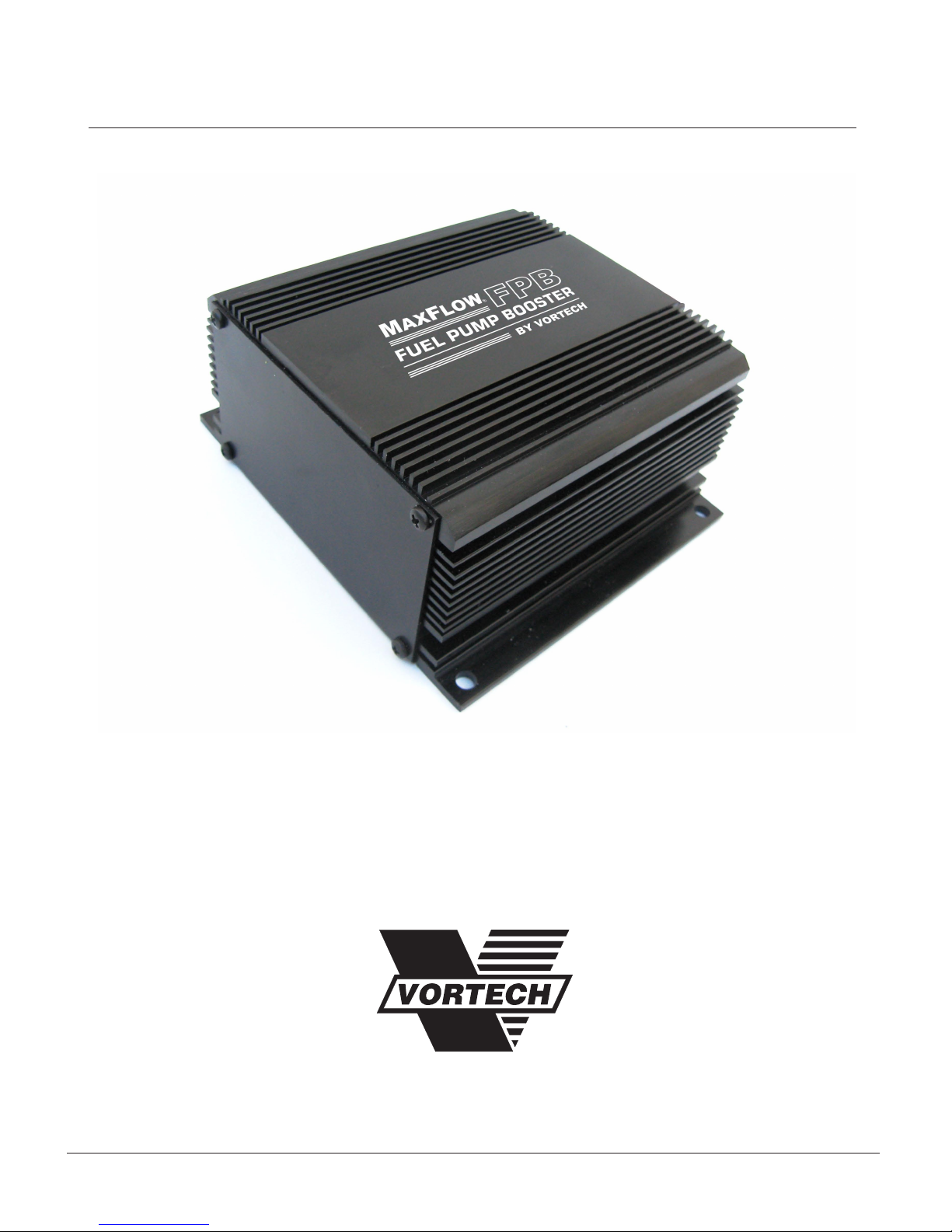
E. Remove the driver's side door sill. Lift up on the
door sill to release the double sided tape securing
the sill to the body. (See Fig 1-d)
F. Remove the electrical connector. (See Fig 1-e)
G. Remove the plastic clip securing the inside panel
and set the panel to the side to be reinstalled in a
later step. (See Fig 1-f)
Fig. 1-d
Fig. 1-e
Fig. 1-f

DP/N: 007127v1.1, 2012-02-21
© 2012 Vortech Engineering, Inc.
All Rights Reserved, Intl. Copr. Secured.
3
1. PREPARATION AND REMOVAL, CONT’D
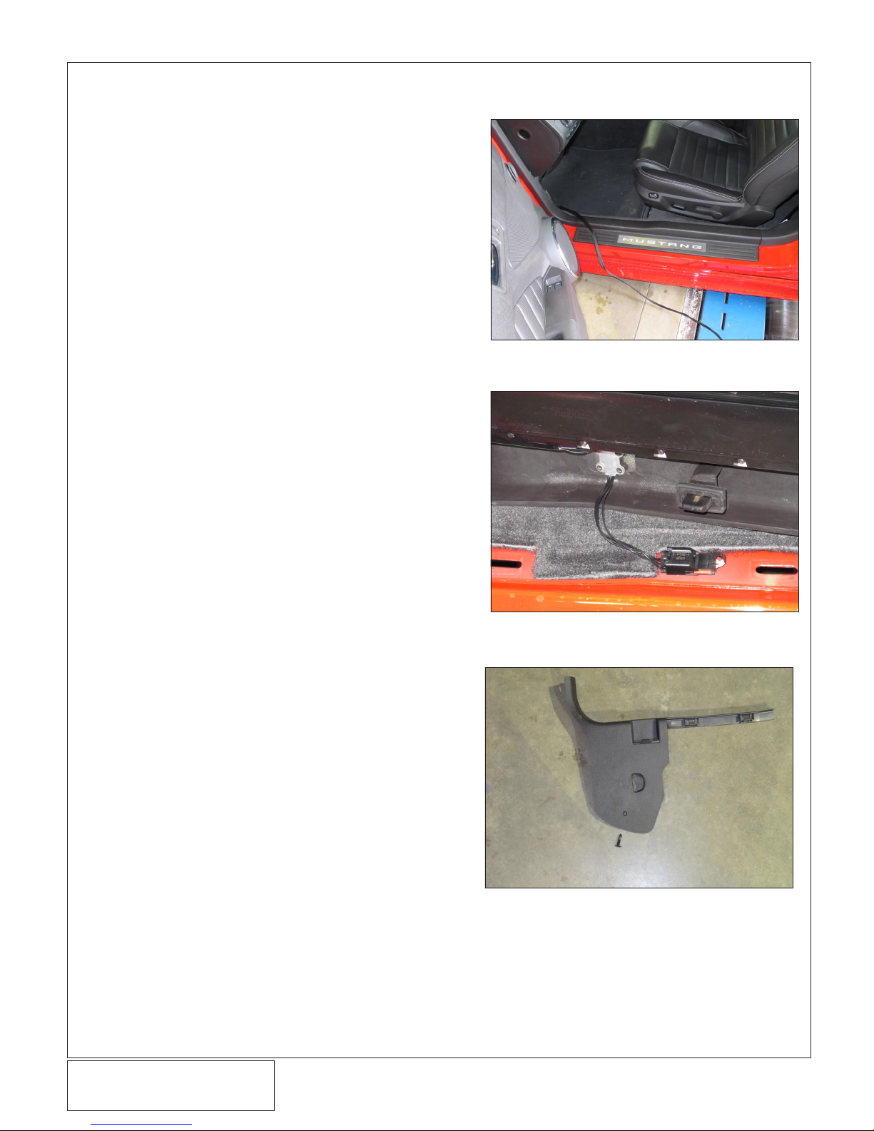
H. Remove the plastic clip securing the lower portion
of the plastic planel just below the rear seat. (See
Fig 1-g)
I. Remove the rear seat. Locate the 2 clips that
secure the seat. Press the clips toward the rear of
the vehicle and lift up on the lower portion of the
seat to release the lower cushion. (See Fig 1-h)
J. Remove the rear trunk carpeting, exposing the
spare tire well. (See Fig 1-i)
Fig. 1-g
Fig. 1-h
Fig. 1-i
PLASTIC
FASTENER
PLASTIC RETAINING CLIP
DP/N: 007127v1.1, 2012-02-21
© 2012 Vortech Engineering, Inc.
All Rights Reserved, Intl. Copr. Secured. 4
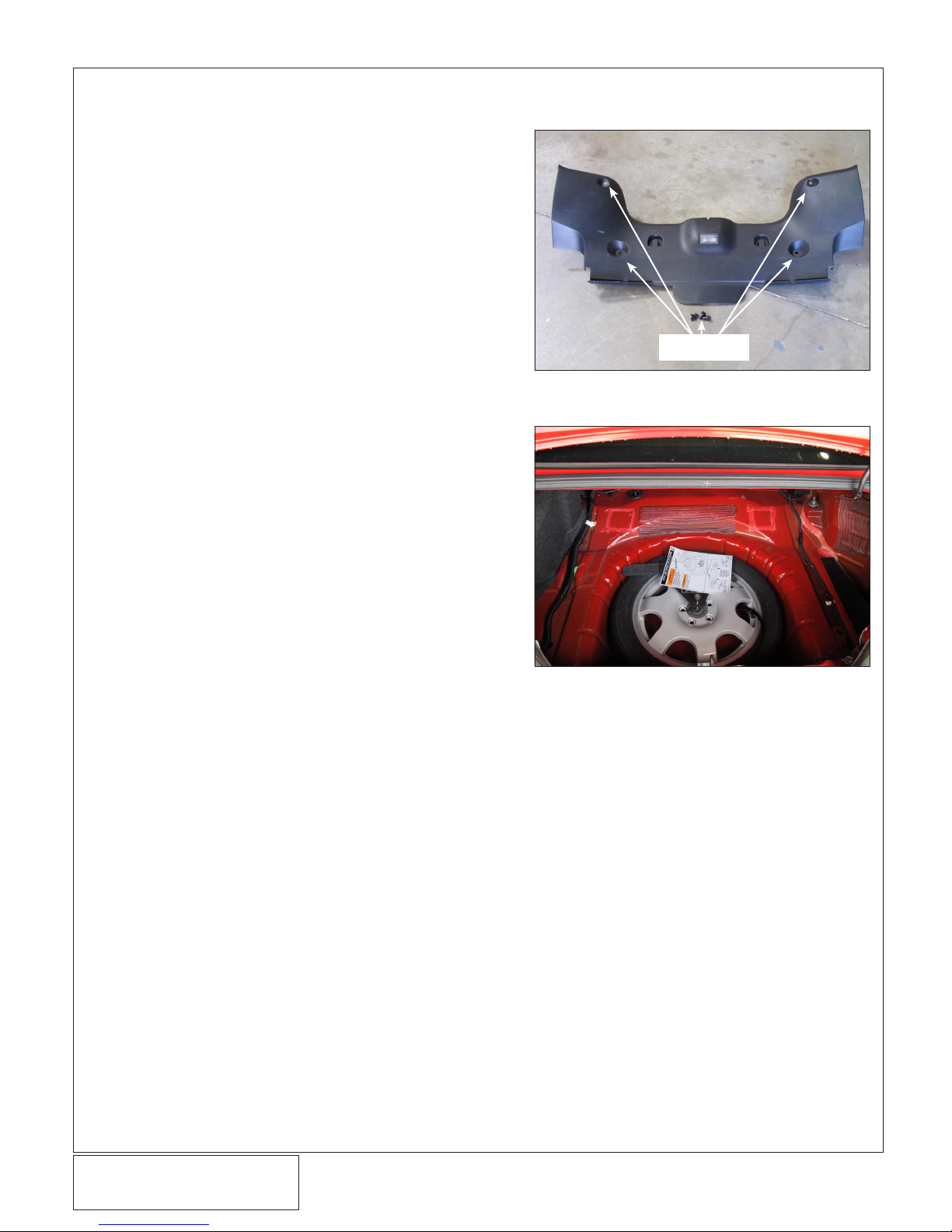
K. Remove the four plastic fasteners securing the
plastic tail light cover. (See Fig 1-j)
L. Lift up on the panel and remove it. It will be rein-
stalled at a later time.
M. Remove the spare tire, if equipped. (See Fig 1-k)
1. PREPARATION AND REMOVAL, CONT’D
Fig. 1-j
Fig. 1-k
REMOVE
FASTENERS
This manual suits for next models
1
Table of contents


