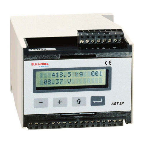
VPG BHL Nobel AST 3 User manual


Analogue Signal Transmitter AST 3
Contents
1. Introduction
Versions ............... 1-1
Functions .............. 1-2
Technical data ......... 1-4
2. Installation
General ................ 2-1
Electrical installation 2-1
Presentation panel, AST 3P .
2-4
Operation indicator, AST 3B
2-5
3. Set-up
General ................ 3-1
Quick set-up ........... 3-3
Normal set-up .......... 3-7
Parameters ............. 3-9
4. Calibration
General ................ 4-1
Common calibration param. 4-
2
Data sheet calibration . 4-3
Dead weight calibration 4-4
Table calibration ...... 4-4
5. Operation
General ................ 5-1
Power supply ........... 5-1
Power-up sequence ...... 5-1
Display views in Oper. mode
5-2
Zero setting ........... 5-3
Analogue output ........ 5-3
Level supervision, relays 5-
4
6. Communication
Communication interface 6-1
Line termination ....... 6-1
Transmission principles. 6-1
Modbus ................. 6-2
Register descr. -Process
param. ................. 6-6
I/O bit (coil) description .
6-11
Exception responses ... 6-12
Set-up registers ...... 6-13
External display ...... 6-14
7. Troubleshooting
General ................ 7-1
Error codes ............ 7-1
Temporary comm. for AST 3B .
7-6
Appendices
Set-up list for AST 3 App. 1
Declaration of Conformity...
App. 2

Technical Manual

Analogue Signal Transmitter AST 3
1-1
1. Introduction
AST 3 is a high performance signal transmitter, designed for
industrial measuring by means of strain gauge transducers.
The compact module is easily installed on a DIN-rail or a
flat surface.
By serial communication a number of AST 3 modules can be
combined to form a network with a common control unit.
Transducer excitation is included in the transmitter module
and the analogue transducer signal is converted to a digital
signal with very high resolution. By parameter controlled
calculations an internal measurement value is produced, which
can be converted to a current or voltage signal at the
analogue output.
The measurement value can also be transmitted to the control
unit, or to an external display unit.
Level supervision at two levels can be performed and the
status is transmitted
over the serial communication.
All AST 3 inputs and outputs are galvanically isolated from each
other and from
the power supply for the unit.
Versions
AST 3 is available in two versions, both including the same
measuring functions and an analogue output:
AST 3B is designed for remote use. An external control unit
is needed
for set-up of parameter values, and it can also be used for
presentation of
the measurement value.
In AST 3B a green LED is visible through a hole in the
panel, indicating
the operating state of the unit.
In AST 3P components are added to make also local use
possible. A front panel with command keys and a
display window allows local parameter
set-up and display of both parameter and measurement
values at the transmitter module. For AST 3P operating
or error conditions are shown at the display window
(the internal LED is not visible).
AST 3P also includes two output relays for indication
or control duties.

Technical Manual
1-2
Functions
Measuring with strain gauge transducers. The output signal
and the sense (representing the excitation voltage) are
measured at the transducer by four wires to avoid influence
from voltage drop in the connection cable.
Excitation to the transducer, from AST 3 or from an external
DC-power supply, is provided over separate wires.
A shielded 6-wire cable must be used to connect AST 3 to a
distant transducer.
A/D conversion. The analogue signal-to-sense ratio from the
transducer is converted to a digital value and filtered to give
an internal transducer signal representation with high
resolution of the load on the transducer.
Calculation. Influenced by calibration data, the internal
transducer signal is converted to a digital measurement value,
the weight value, that can be presented at the local display
window and at the control unit.
Analogue output. The calculated weight value is also converted
into an analogue output signal, e.g. for presentation on an
external display. Current or voltage output can be selected. The
analogue output can also be forced to produce a selected, fixed
current or voltage signal.
Error supervision. The error supervision is checking for
electrical errors, invalid parameter values, and signals out
of valid limits. As long as no error is detected,
the signal ‘In process’ is present. If an error is detected an
error message will be displayed and the signal ‘In process’
Figure 1. The Analogue Signal Transmitter AST 3 converts analogue
transducer signals
into precise measurement values for use in industrial processes.

Analogue Signal Transmitter AST 3
1-3
will be off, the relays will be deactivated, and the analogue
output signal will be set to 0V / 0mA.

Technical Manual
1-4
Levels. Two level comparators in AST 3 can be set to switch at
defined levels
for selected signals, reporting the status of the signals to the
control unit.
In AST 3P two switching relays are included. They can be set to
indicate
the status of the level comparators or the status of the signal
‘In process’.
Serial communication. In AST 3 the serial interface RS-485,
on 2-wires or
4-wires, is used for communication with the control unit.
Set-up and calibration parameters, weight value, level
status, error status etc. is transmitted via
the Modbus protocol.
If the serial interface is not used for control unit
communication, it can be used to transmit the weight value
to external digital equipment.
Instrument modes. At power-on the unit enters the Start-up
mode, displaying its identity while internal tests are
performed.
Then it may enter the Wait for start mode (selected by a
parameter), waiting for a start command from the operator.
After completed start-up, the AST 3 unit is normally
working in Operating mode, continuously presenting the
weight value (or other selected information).
If editing of set-up parameters should be performed, AST 3
must be switched over to Set-up mode.
If an error is detected, AST 3 will automatically switch
over to Error mode, displaying an error message.
As AST 3 is in Set-up mode or Error mode, normal instrument
operation is disabled, the relays are deactivated, and the
analogue output is set to zero.
Parameter setting. In AST 3 set-up parameters are used to
control all operating functions. The parameter values can be
entered as numerical values or selected from a list of
alternatives.
Setting of the parameter values can be performed from a
control unit.
For AST 3P, the front panel keys and display window can also
be used for
the parameter setting.

Analogue Signal Transmitter AST 3
1-5
Presentation. AST 3 can present parameter values and measured
or calculated signal values at a control unit, and for AST 3P
at the panel display.
The measurement value is also presented by the analogue output
signal.
Controlunit
AST3B
AST3P
PC
AST3P External
display
RS-485
RS-485
Figure 2. The AST 3 versions can utilise serial communication
to carry out different operational tasks.

Technical Manual
1-6
Technical data
Transducer input
Transducers Max 8, 350 ohms each. Total load >45 ohms.
Excitation Depending on the number of transducers
connected:
8.8 VDC 5 % with 1 transd. 8.7 VDC 5 %
with 2 transd.
8.5 VDC 5 % with 3 transd. 7.7 VDC 5 %
with 4 transd.
6.5 VDC 5 % with 6 transd. 5.5 VDC 5 %
with 8 transd.
Signal input 3.3 mV/V.
Sense input 1.5 –10 VDC.
A/D conversion 23 bits (8 300 000 counts). Patented design.
Analogue output
Bipolar voltage or current.
Voltage 0–10 VDC or +/-10 VDC over >500 ohms.
Current 0–20 mA, +/-20 mA, 4–20 mA, -12–20 mA in <500
ohms.
Filter 0.05 to 75 Hz, selectable bandwidth.
Resolution 16 bits (65 000 counts).
Non-linearity <0.01 % of range.
Zero drift <0.005 % of range/C.
Gain drift <0.003 % of actual value/°C.
Serial output
Can be used for control unit communication (Modbus) or external
display.
Interface RS-485, 2-wires or 4-wires.
Baud rate Up to 115.2 kbaud.
Data format Modbus RTU protocol for control unit
communication.
30
735
75
100
110
5
60
85
Mountingholes,
2x4mmdia.
Thesnapfastenerfor
DINrailcanbeopened
withafinescrewdriver.
Figure 3. Mechanical dimensions for AST 3.

Analogue Signal Transmitter AST 3
1-7
Filter 0.05 to 75 Hz, selectable bandwidth.
Non-linearity <0.005 % of range.
Zero drift <0.0002 % of 3.3 mV/V /C.
Gain drift <0.0015 % of actual value/°C.

Technical Manual
1-8
Calibration
Methods Data sheet, Dead weight or Table.
Power supply
Supply voltage 24 VDC ±20 %.
Consumption 7 W.
Environmental
Temperature range –10 to +50 °C.
CE conformity EMC, industrial for process control.
Mechanical data
Dimensions 75 x 100 x 110 mm.
At least 10 mm air gap between units.
Rail mount DIN 46 277/3 and DIN EN 50022 (35 mm).
Protection IP 20.
Relay output (for AST 3P only):
Number of relays 2 (each with 1 switching group).
Relay load Max 1 A, 30 V AC or DC.
Spark suppression required at inductive load.
Front panel (for AST 3P only):
Display 2 x 16 character LCD display.
Keys 4 keys for menu control and data entry.
Figure 4. AST 3P and a rail mounted power supply
in a protecting box from Nobel Weighing Systems.

Analogue Signal Transmitter AST 3
1-9
Figure 5. The Analogue Signal Transmitter AST 3P.


Analogue Signal Transmitter AST 3
2-1
2. Installation
General
Each signal transmitter module AST 3 contains several circuit
boards, built
into a protective plastic housing. The module can be snap-
mounted on a
35 mm wide DIN rail or attached on a flat surface by two 4 mm
screws.
Two groups of plug-in terminals for the cables are arranged on
the module.
The transducer cable is connected on one side of the module and
all other
cables on the opposite side.
Electrical installation
All electrical connections to the AST 3 module, including
possible connection to ground, are made via plug-in terminal
blocks. Shielded cables are needed, except for the power
supply, and the cables should be routed so that electro-
magnetic interference from power cables is avoided.
Input and output signals for AST 3 are galvanically isolated
from each other to facilitate connection to various external
equipment.
Cable connection is shown in the
diagrams below.
Power supply
Terminals 17, 18.
The AST 3 unit is powered by 24 VDC,
see requirements in Technical data.
Nobel Weighing Systems provides rail mounted
power supplies, intended for operation
of AST 3 units.
Analogue output
Terminals 24, 25.
Current output or voltage output for
presentation
of the measured value at the process control or
at an external analogue instrument.
Connect the cable shield to ground, preferably to
a ground terminal at the mounting rail.
17
+
-
18
+24VDC
0V(24) 24V
+
OUT+
OUT–
24
25

Technical Manual
2-2
Serial communication
Terminals 19 –23.
A serial port for RS-485, on 2-wire
or 4-wire
with common signal ground (COM), is
used to connect AST 3 to a control
unit, or to transmit values to an
external display unit.
At both ends, the transmission line
must have terminating resistors of
120 ohms. For AST 3
they should be mounted on separate
terminals and be connected according
to these diagrams.
For a control unit or external
display, refer to manufacturer
instructions concerning line
termination.
Shielded cable with twisted pairs
should be used, the cable shield
connected to ground, preferably
by a ground terminal on the mounting
rail.
When connecting several units to a
transmission line, wires from two cables must be connected to
the terminals at AST 3.
To facilitate that connection, use cable ferrules crimped on the
two wires.
Relay outputs (AST 3P only)
Terminals 9 –11 and 12 –14.
These outputs are present only at AST 3P.
Observe the contact ratings given in
Technical data.
Use shielded cable connected to ground,
preferably by a ground terminal on the
mounting rail.
When the relays are used, the installation
contractor has to observe the requirements
of interference emission for electrical and
electronic devices (EN 50081) on the contact side
and take appropriate measures, if necessary.
2-wire
*
Terminatingresistoronseparate
terminalsatthelastunitontheline.
19
20
21
22
23
TXD–
TXD+
RXD–
RXD+
COM.
4-wire
Terminatingresistoronseparate
terminalsatthelastunitontheline.
*
*
19
20
21
22
23
TXD–
TXD+
RXD–
RXD+
COM.
*
*
R1C
9
10
11
12
13
14
R1NC
R1NO
R2C
R2NC
R2NO

Analogue Signal Transmitter AST 3
2-3
Transducer input
Terminals 1 –7 (8).
Connection of transducers should be handled with great care to
achieve good measuring data. For transducers delivered with
integrated connection cable,
this cable must not be shortened.
NOTE! Transducer cables must be routed at least 200 mm away from
230/380 V,
50/60 Hz power cables. By cables with other frequencies or high
power, an even
wider distance is preferable.
AST 3 is designed for 4-wire connection or 6-wire connection of
transducers.
4-wire connection should be used if the cable, delivered with
the transducer,
can be connected directly to the AST 3 terminals. By 4-wire
connection,
excitation and sense must be interconnected as shown in the
diagram below.
Connect the cable shield and terminal 5 to ground via the
mounting rail.
6-wire connection should be used if the cable, delivered with
2
1
3
6
4
7
EXC+
SENSE+
SHIELD
SIGN.+
Excitation+
Excitation-
Signal+
Signal-
Transducer
JunctionboxSL-4
4-wireconnection
6-wireconnection
5
8
CAL
EXC–
SENSE–
SIGN.–
Exc.+
Sign.-
Exc.-
Sign.+
Transducer
Transducer
Transducer
J11
J12
J13
J14
J1
J101
J102
J103
J104
J106
J108
J10
J105
J107
J59
J58
CAL
R
EXC+
SENSE+
SHIELD
SIGN.+
CAL
EXC–
SENSE–
SIGN.–
Exc.+
Sign.-
Exc.-
Sign.+
Exc.+
Sign.-
Exc.-
Sign.+
J21
J22
J23
J24
J31
J32
J33
J34
J41
J42
J43
J44
J2
J3
J4
2
1
3
6
4
7
5
8

Technical Manual
2-4
the transducer must
be lengthened, or if several transducers should be connected to
one AST 3 unit.
Connect the transducer cable(s) to a junction box, and use 6-
wire connection
between the junction box and AST 3. Connect the cable shield and
terminal 5
to ground via the mounting rail. In the diagram below
connections are shown for
the junction box SL-4 from Nobel Weighing Systems.

Analogue Signal Transmitter AST 3
2-5
Presentation panel, AST 3P
The presentation panel of AST 3P has a 2x16 character LCD display
and four keys.
In Operating mode the weight value is presented in one view, but
other views may also be selected.
Set-up can be performed in two ways: the ‘Quick set-up’ with only
a few vital parameters or the ‘Normal set-up’ with all the
parameters available.
Error messages or parameter explanations can also be displayed.
The keys are used to select a parameter, to edit the parameter
value, and to save
the new value in the memory or to exit without saving the new
value.
The key functions in the different modes are explained in the
table below.
Key explanation
Name
Function
In Operating mode: In Set-up mode:
ENTER
In view Zero setting: In a ‘Main menu’:
Set the value to zero. Go to the first
parameter.
In all other views: Parameter viewing, without
cursor:
No function. Make editing possible.
Parameter editing, with
cursor:
Accept the digit at the
cursor
and go to next digit.
If ENTER is pressed for 2
seconds:
The displayed parameter
value is
activated. The cursor
disappears.
plus
Go to next view. In a ‘Main menu’:
See Figure 12. Go to next main menu.
Together with for 2 sec.: Parameter viewing,
without cursor:
Go to ‘Normal set-up’. Go to next parameter.
(Password may be required.) Parameter editing,
with cursor:
Increment the digit at the
cursor or
Go to next alternative.
minus
Go to previous view. In a ‘Main menu’:
See Figure 12. Go to previous main menu.
Parameter viewing, without
cursor:
Go to previous parameter.
Parameter editing, with

Technical Manual
2-6
cursor:
Decrement the digit at the
cursor or
Go to previous
alternative.
ESCAPE
If pressed for 2 seconds: In a ‘Main menu’:
Go to ‘Quick set-up’. No function.
(Password may be required.)
If held while + is Parameter viewing, without
cursor:
pressed for 2 seconds: Go to the main menu.
Go to ‘Normal set-up’. Parameter editing, with
cursor:
(Password may be required.) Interrupt the
editing.

Analogue Signal Transmitter AST 3
2-7
Example for how to use the keys:
As an AST 3P is started for the first time it enters the
Operating mode, displaying the Weight value. This example
describes how to change ‘Measurement unit’ to pounds (lb) and
Capacity to 1000 (lb), using the ‘Quick set-up’. See figure 7.
* To leave Operating mode and enter ‘Quick set-up’, press for
2 seconds.
* ‘Main menu Quick set-up’ is displayed. Press to get to the
first parameter
in the ‘Quick set-up’.
* The first parameter, ‘Language’, is displayed. Press to get to
‘Measurement unit’.
* For parameter ‘Measurement unit’, the default value ‘kg’ is
displayed.
Press to start editing. A cursor makes the first letter on the
lower line blinking.
* With a cursor on the lower line or are used to step
forwards or
backwards through the list of alternatives. Press or
until ‘lb’ is displayed.
* To accept the displayed alternative, press for 2 seconds.
The cursor disappears.
* Now, without cursor on the lower line, use to get to parameter
‘Capacity’.
The default value on the lower line, 500.0 lb, should be changed
to 1000.0 lb.
* Press to start editing.
The lower line will display ‘00500.0 lb’ with a cursor at the
first digit.
* The parameter value should be changed to ‘01000.0 lb’.
Press once to accept the first digit and move to the second
digit.
Press or to change the digit to ‘1’.
Press to accept the value ‘1’ and move to next digit.
Press or to change the digit from ‘5’ to ‘0’. Now the
value is correct.
Press for 2 seconds, the cursor disappears and ‘1000.0 lb’
is displayed.
* As the editing is ready, press to get to ‘Main menu Exit
set-up’.
* Press . The sub menu ‘Save changes? No Esc. Yes’ will
be displayed.
(Press if you do not wish to exit from the set-up mode.)
* Answer by (Yes) to save the new edited values.
Answer by (No) to cancel the new values and
return to previously saved values.
Other manuals for BHL Nobel AST 3
1
This manual suits for next models
2
Table of contents
Other VPG Transmitter manuals
Popular Transmitter manuals by other brands

Inovonics
Inovonics EchoStream EN1235SF installation instructions

Endress+Hauser
Endress+Hauser iTEMP TMT86 operating instructions

brel-motors
brel-motors DD-2762H manual

BD Sensors
BD Sensors IMK 331 Mounting instructions

ABB
ABB LMT100 quick start guide

Mercoid
Mercoid 3200 Series Installation and operating instructions

Jamara
Jamara FCX6 Pro Tel Instruction

Transmitter Solutions
Transmitter Solutions Stinger2 300MCD22V2 manual

Moseley
Moseley PCL-303/C instruction manual

Christie
Christie Link user guide

Neptune Technology
Neptune Technology L900 MIU Pit Installation and maintenance guide

Emerson
Emerson ROSEMOUNT 5300 Manual supplement